IJEDR1701119
International Journal of Engineering Development and Research (www.ijedr.org)748
DESIGN AND DEVELOPMENT OF JIG
FOR AN AUTO PART
Kataria Mahendra B.
1, Bhimani Jasmin.
21
Assistant Professor, Mechanical Engineering Depart ment, Aditya Silver Oak, Ah medabad, Guja rat, India 2
Assistant Professor, Mechanical Engineering Depart ment, Vvp Engineering College Ra jkot, Guja rat, India
_______________________________________________________________________________ ________________________
Abstract— there are many types of jigs and fixtures are used in industries. Jig is device which is used to hold the work piece or fix t he work piece and guide the cutting tool. The purpose of the jigs is to provide strength, holdi ng, accuracy and interchangeability in the manufacturing of product. The objective of this project is to design and development of drill jig. We found that there is pro blem in auto part which required three holes of diameter 8.05mm at 120° with the help of drilling manually. It is time consuming process. Also skills and accuracy is required. So with the use of jig time con sumption for drilling three holes is less. Drilling jigs make possible t he drilling of holes at higher speed with greater accuracy and with less skilled worker.
Index Terms— jig and fixture, holding devices, drilling machine. Plate etc.
________________________________________________________________________________________________________
1.IN TRO DUC TION
Minimat ic Machine is a SSI unit based established in the year 1984 at Ra jkot, which is catering to the needs of OE as we ll as ancillary units located in this region. The main thrust of the activity of the unit basically is to provide difficu lt to manu facture Jigs, Fixtures & Measuring Instruments in the workshop of the OE suppliers. A co mp lete Tool Roo m type setup has been completed by Min imatic Mach ines at their factory site.
The name of the industry is Minimatic Machines. The owner o f the industry is Mr. Jaysukh Nagewadia. The industry manufactures CNC turn ing machines. Types of the turning centers are MGT50, M GT100, and M GT200. A lso they manufacture VM C200. Industry also manufactures special purpose machines, measuring instruments and different auto parts. Special purpose mach ines like abras ive belt grinder, bench center and measuring instruments like ca m profile checking unit, comparator stand, dial ca libration stand, run-out checking instruments are made.
2. INTRODUCTION OF J IG
It is a work holding device that holds, supports and locates the work piece and guides the tool for a very specific operation. Increasing the productivity and accuracy are the two basic aims of mass production. As we know the solution to this is by reducing the set up cost of the machine and also reducing the manual fa tigue. In this case the device that caters our needs is the use of jigs. Let us take one e xa mp le. Let us consider that one gets an order of say 1000 products. There need to be three hol es drilled on this product. Accuracy is the main proble m in such cases. In doing so it increases the work load on the operator. Hence using of jig to position and guide the tool to its right path is preferred rather than using scribers, square, straighteners or center punch etc. Thus the productivity is increased which is don e by eliminating individual positioning, marking and frequent checking. Interchangeability is the chief advantage here. All the parts fit in properly except only the similar co mponents are interchangeable. One does not need to repeatedly clamp and uncla mp the object for various purposes like positioning as the locating, cla mping and guiding of the tool is done by the jig itself. Bushing which is a tool guiding tool is used. So it red uces the presence of skilled laborer. Drill jig helps to drill, rea m and tap at a much faster speed and with great accuracy as compared to holes done conventionally by hand. In case of a drill jig bushings are used. These drill bushings guide the drill b it during the drilling operation. Generally work piece is held by a fixture and the fixture is arranged in such a way that the loading and unloading of the job is quick.
Fig. 1 jig 2.1 PROB LEM S UMMARY:
IJEDR1701119
International Journal of Engineering Development and Research (www.ijedr.org)749
operation, marking and punching are done manually. So more t ime is required for ma rking and punching. . Moreover the setting and holding of job during machining is difficult and time consuming task. Also more time required for inspection of bore diameter.2.2 INDUS TRIAL PROCESS (PRESS URE PLATE):
- The pressure plate which is made with the help of casting process. Sand casting is used for manufacturing pressure plat. - After casting process, rough machining process is done with the help of different tools.
Fig. 2.1 Pressure plate (3D) Fig. 2.2 Pressure plate (3D)
- After completion of the rough finishing process, final finishing processes like filing and polishing are done.
- Then inspection is carried out on the part. In the inspection process, checking the internal and outside diameter is carried out.
- After completion of the inspection, drilling operation is carried out for drilling 3 holes (120 degree) on the part.
Fig. 2.3 Side of Pressure plate
- After drilling operation, chamfering on the holes is carried out and also final inspection of the part is carried out. - After chamfering, final inspection, plating and painting are done.
Fig. 2.4(Cha mfering) Fig. 2.5(Cha mfering
3. PROB LEM SPECIFICATION:
IJEDR1701119
International Journal of Engineering Development and Research (www.ijedr.org)750
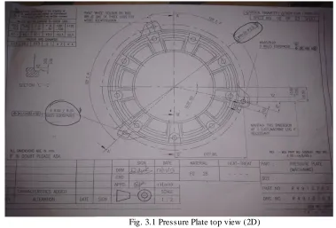
- So more t ime is required for ma rking and punching at 120 d egree angle and pitch circle d ia meter o f 261.5mm. - Also more t ime required for inspection of bore diameter.Fig. 3.1 Pressure Plate top view (2D)
4 CLAMPING DEVICES
There are diffe rent types of clamps wh ich help in cla mp ing of the jig at the required position. Cla mps hold the work piece firmly. This helps in better engagement of job during the operation. Va rious forces develop during the cutting operation. The cla mping should be such that it will sustain these forces during the operation. At the same time if cla mp ing is so tight that it damages the work piece then it must be avoided. The timing required for c la mp ing and unclamp ing of the device should be as le ss as possible. These cla mping must also restrict vibrations and chatter during the cutting operation.
4.1. TYPES OF CLAMPS:-
1. Screw Clamps:
These are widely used for jigs and fixtures. These have lower costs. However, their operating speed is quite slow. The basic screw cla mp uses the torque developed by a screw thread to hold a part in place. This is done by direct pressure or by acting on another cla mp.
Fig. 4.1 Scre w Cla mp 2. Cam-action Clamps:
Ca m-action cla mps, when properly used, provide a fast, efficient, and simp le way to hold work. Due to their construction and basic operating princip les, the use of cam-action c la mps is limited in so me types of tools.
3. Hi nge d Cl amps:
IJEDR1701119
International Journal of Engineering Development and Research (www.ijedr.org)751
Fig. 4.2 ca m action Cla mp Fig. 4.3 hinged Cla mp
5. OUTLINE OF THE SOLUTION:
In the manufacturing of pressure plate different operations and process like casting, inspection, drilling, cha mfering is don e. In drilling operation, marking and punching are done manually. So more time is required for marking and punching. . Moreover the setting and holding of job during machin ing is difficult and time consuming task. Also more time required for inspection of b ore dia meter.
So we have suggested and design a JIG for drilling process.
5.1. DES IGN PROCESS OF JIG:
RAW MATERIAL:-Base plate (310*20 mm) Square bar (180* 40* 20 mm) Square bar (180* 40* 8 mm)
PROCEDURE:-FIG. 5.1 Design Procedure of Jig
BAS E PLATE:-
- First take base plate of dia. 310 mm *20 mm. Fac ing and turning operation is carried out on the base plate for straightness. Then step turning of dia. 150.1 mm is done.
- Drilling of dia . mm is done at the center of the base plate.
IJEDR1701119
International Journal of Engineering Development and Research (www.ijedr.org)752
FIG. 5.2 Base Plate SQUARE BAR:-
- First take square bar of 180* 40* 20 mm. marking at length of 30mm, 60mm and 90mm is carried out consequently. Then the cutting operation of two square bar is carried out with the help of hac ksaw cutting mach ine as per the Marking. - Then drill two holes (as per size of bolts) at the bottom of the First square bar with the use of base plate and a lso tapping
of the holes are carried out.
- After that drill two holes of same size at top of that first square bar and also on the second square bar as per the first square bar. Then jo int two square bar with the help of l & key bolt.
- Drill one hole of dia . 8 mm on the top of that plate with the use of pressure plate. - Sa me procedure is done for the re ma ining two holes of the pressure plate.
FIG.5.3 Square Bars 6. SUMMERY OF RES ULT
6.1. TIME ANALYS IS:-
CALCULATIONS:- Drill Size : 8mm or 5/16 Inch Feed Rate : 0.123 mm / rev FOR 610 RPM :-
1) Materia l Re moval Rate MRR = П* D2 *f*N/4 = П* (8)2 *0.123* 610/4 = 3771.4 mm3 / min 2) Total Depth
Total Depth L = Total he ight + 2* 0.29* D = 20 + 2*0.29*8
= 24.64 mm 3) Drilling Time Drilling Time T = L/ N*f = 24.64/610*0.123 = 59.112 sec
IJEDR1701119
International Journal of Engineering Development and Research (www.ijedr.org)753
Total Time = Loading and Unloading Time + Drilling Time for Drill 3 holes= 51 + 59.112*3 = 231 sec FOR 912 RPM :-
6) Materia l Re moval Rate MRR = П* D2 *f*N/ 4 = П* (8)2 *0.123* 912/4 = 5638.58 mm3 / min 7) Total Depth
Total Depth L = Total he ight + 2* 0.29* D = 20 + 2*0.29*8
= 24.64 mm
8) Load ing and Unloading Time = 51 sec 9) Total Time
Total Time = Loading and Unloading Time + Drilling Time for Drill 3 holes = 51 + 39.5377*3
= 171 sec
OPERATION EXISTING SOLUTION PROPOSED SOLUTION (USING JIG) By standard table By measurement
Marking and punching 690 sec --- ---
Loading and unloading time 20 sec 51 sec 51 sec
Drilling time 40 sec 60 sec 40 sec
Total time 750 sec 231 sec 171 sec
Table No.:- 6.1 Time ana lysis 7. CONCLUS ION:-
After this project we conclude that operation time reduces, accuracy increases and also production rate increases.
Productivity: Jigs and fixtures eliminate the individual ma rking, positioning, and frequent checking. This reduces operation time increases productivity.
Interchangeability: Jigs and fixtures facilitate uniform quality in manufacture. There is no need for selective assembly. Any part of the mach ine fit properly in assembly, and a ll simila r co mponents are interchangeable.
Skill Reduction: Jigs and fixtures simplify locating and clamping of the work pieces. Tool guiding elements ensure correct positioning of the tools with respect to work p ieces. There is no need of skillful setting of the wo rk piece of tool. Any average can be trained to use jigs and fixtu res the replace ment of the skilled work man with unskilled labor can e ffect substantial savin g in labor cost.
Cost Reduction: Higher production, reduction of scrap, easy assembly and savings in labor costs results in substantial reduction in the cost of the work p ieces produced with jigs and fixtures.
8.REFER ENC ES
1. Shivanand Vathare, Shrinivas L Go mb i, Darshan M Katgeri, “ Design and Analysis of Drill Jig for Head and Cover Part of the Actuator”, (IJERT), August – 2014, Vo l. 3 Issue 8, Page no.: 184 – 191. [1]
2. Ha mad Mohammed Abouhenidi, “Jig and Fixture Design”, (IJSER), February-2014, Vo lu me 5, Issue 2, Page no.: 142 – 153.[2]
3. Muthukumaran, Ravi, C.Sivara m, Dinesh, P.S. Ba la ji, C.Sadasivam, A.Muniappan, “Design and Fabrication of Latch Jig for Contour Profile Co mponent”, (IJSR), November-2014, Vo lu me: 3, Page no.: 199 – 201[3].
4. Sawita D. Dongre, Pro f. U. D. Gu lhane, Ha rshal C. Kuttarmare, “Design and Fin ite Ele ment Analysis of JIGS and Fixtures for Manufacturing of Chassis Bracket”,