R E S E A R C H A R T I C L E
Open Access
Automatic design algorithms for securing the
ground contact stability of mobile cranes
Donghoon Lee
1, Jun Young Park
1, Jongkwan Ho
2and Sunkuk Kim
1*Abstract
Background:Mobile cranes overturn due to excessive lifting, heavy wind, or when appropriate ground contact pressure is not secured. Such accidents can be prevented by reviewing the force conveyed from the outrigger to the ground upon lifting, as well as the soil bearing force. The stability review of mobile crane overturn is classified into the following stages: reviewing lifting conditions, mobile crane selection and reviewing ground contact stability. However, a precise review of ground contact stability requires expertise and is extremely time-consuming. Thus, this study develops automatic design algorithms for securing the ground stability of mobile cranes for easy and quick stability reviews.
Methods:The stability review method and the algorithm models are created in connection with the proposed conceptual process. The algorithms proposed in this study conduct simulations for all possible candidate cases, save the results in a database, review practical alternatives, and select the solution that minimizes cost. To verify the effectiveness of the automatic design model, a case project was selected and the algorithm was applied assuming several conditions.
Results:Developed algorithms can select candidate cranes according to lifting conditions and design plates through simulations easily and quickly, and design components required for ground contact plate design are collected to build the database that allows easier and quicker stability review.
Conclusion:The algorithms proposed in this study conduct simulations for all possible candidate cases, save the results in a database, review practical alternatives, and select the solution that minimizes cost. Developed processes are useful for analyzing correlations of mobile crane performance, ground contact and soil bearing force
reinforcement designs and so forth, and for systematically selecting optimal mobile cranes.
Keywords:Mobile crane; Stability; Lifting plan; Ground contact pressure; Automatic design model
Background
Many crane accidents occur globally, including the over-turn of mobile cranes in Phuket, Thailand and England (The Vertikal Press 2014). As the use of cranes increases in South Korea, the number of overturn accidents is gradually increasing, and accidents related to mobile cranes account for approximately 61.4% of all crane acci-dents (Kim and Lee 2007). Overturn of mobile cranes occurs due to excessive lifting, heavy wind, or when ap-propriate ground contact pressure is not secured. Such accidents can be minimized by reviewing the force that is conveyed from the outrigger to the ground upon lifting
and the soil bearing force. The stability review of mobile crane overturn is classified into the following stages: reviewing lifting conditions, mobile crane selection, and reviewing ground contact stability. For safe operation, stage-by-stage reviews are needed.
Stability should be pre-reviewed, and it is reasonable to select mobile cranes among the candidate cranes that have completed reviews in consideration of cost or other factors. However, engineers or technicians do not set lift-ing plans that suit the construction conditions for stabil-ity analyses when implementing construction projects; instead, equipment is operated based on the information provided by an equipment supplier. Operation relying on such limited information and experience is the fundamen-tal cause of crane disasters (Ho, Han and Kim 2007). In * Correspondence:[email protected]
1
Department of Architectural Engineering, Kyung Hee University, 1732 Deogyeong-dearo, Giheung-gu, Yongin-si, Gyeonggi-do, Korea Full list of author information is available at the end of the article
addition, since such an approach makes precise reviews of mobile cranes and working conditions impossible, it is dif-ficult to select the optimal mobile crane.
There are two factors that prevent engineers or techni-cians from setting detailed mobile plans. First, it is difficult and extremely time-consuming to consider the ground contact stability applied to mobile cranes. Second, there is not enough of a systematic technique for analyzing a lot of data for stability review of candidates. There have been previous studies that investigated the selection of optimal cranes, taking into account the lifting capacity of mobile cranes and transporting routes (Reddy and Koshy 2002; Al-Hussein et al. 2001; Tantisevi and Burcu 2007). How-ever, those previous studies did not include detailed stabil-ity reviews such as the soil bearing force and ground reinforcement. Therefore, this study intends to move beyond the limits of previous studies and develop automatic design algorithms for securing the ground contact stability of mobile cranes. The algorithms proposed in this study focus on the ground stability review process of mobile cranes.
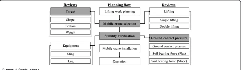
For stability review of cranes, this study limits scope to improve the efficiency of the study and the reliability of its results. Above all, the study subject is limited to the hydraulic crane (or tire crane) that uses an outrigger among mobile cranes. The lifting method can be divided into single lifting and double lifting, and the study is conducted assuming single lifting. In the case of double lifting, more than two working radii and the soil bearing force should be reviewed, and the distance from the crane should be considered. Thus, double lifting has a different method of stability review, and an additional study should be carried out based on this study result. Also, as shown in Figure 1, the study reviews the ground contact stability. The range of reinforcement of soil bearing force occurs when the crane is installed on soil or ground, and this study excludes cases in which it is installed on top of a structure. The reinforcement of structure has a different procedure for reviewing bending, shearing, and sagging compared to that of soil or ground, so it requires a different model. Lastly, the study is
conducted assuming that the boom, sling, and lug meet the lifting requirements, and there is no stability review for each of these materials.
Methods
To achieve the objective of this study, first, ground con-tact stability review items are identified and a conceptual process is developed. Second, the conceptual process for reinforcing ground contact pressure and soil bearing force is proposed. Third, a stability review method and algorithm models are created in connection with the proposed conceptual process. Finally, automatic models among the created models are developed, taking into ac-count safety and economic feasibility. The developed processes analyzes correlations among the performance of mobile cranes, ground contact, and soil bearing force reinforcement and so on in order to assist the systematic selection of optimal mobile cranes.
Literature review
Studies related to crane selection and stability review have been conducted using a wide range of methods. Reddy and Koshy developed a lifting route plan program considering the working radius and lifting capacity of mobile cranes (Reddy and Koshy 2002). Al-Hussein et al. implemented an optimal crane selection algorithm using Visual Basic in consideration of the lifting capacity of mobile cranes (Al-Hussein et al. 2001). However, the studies mentioned above did not consider ground condi-tions, including the soil bearing force. Tantisevi and Burcu (2007) analyzed and controlled the work space and visual/ spatial movement of mobile cranes to minimize friction with other works and delays (Tantisevi and Burcu 2007). This is useful in an effective arrangement and operation of mobile cranes, but it is far from a detailed stability review. Tamate et al. analyzed outrigger loads that cause overturn of mobile cranes. They also conducted an experiment on overturn of mobile cranes as the load is delivered to the outrigger and analyzed the result; however, they did not propose the selection of stability-secured mobile cranes
and plate design algorithms like this study (Tamate et al. 2005). Shapira et al. considered the characteristics of building projects and conducted a study in selecting whether a mobile crane or a tower crane is most suitable. Also, the items to consider in choosing the detailed model (building, site, safety, air, weather, etc.) were analyzed to identify the importance of each item (Shapira and Schexnayder 1999). However, there was no stability review or selection procedure in relation to the items considered. Alkass and Osama developed a simulation program to select cranes by using tools like database management, spreadsheet ap-plication programs, graphics, and simulation (Al-Hussein et al. 1997). Similarly, Struková and Ištvánik developed a program to select the optimal location of mobile cranes considering the lifting location, weight and building shape (Struková and Ištvánik 2011). However, there was not enough detailed review on stability of the soil bearing force and the program was aimed at selecting cranes in consider-ation of lifting conditions such as the weight, height, and building shape.
Furusaka and Gray used the objective function that minimizes rental, installation, and disconnection costs to select an optimal crane, proposing a model that combines various tower cranes (Furusaka and Gray 1984). However, their proposal was not a stability review of mobile cranes. Gray and Little suggested a process of selecting mobile cranes and tower cranes that suit designs at the initial de-sign phase (Gray and Little 1985). However, there was no method of reviewing the stability of the selected cranes or of using the available crane information in the market. Ali et al. studied collision avoidance upon the double lifting of a mobile crane, and Perez et al. developed an algorithm for planning collision-free paths among polyhedral ob-stacles (Lozano-Pérez and Wesley 1979). Other studies include those conducted by Maczynski and Wojciech, who developed a 3D optimization algorithm of a rotat-ing part to secure rigidity of mobile cranes (Maczynski and Wojciech 2003), and Lin and Haas (1996), who de-veloped a double lifting simulation program (Lin and Haas 1996). These studies did not consider the ground contact stability of mobile cranes. Lastly, Ho et al. stud-ied a method of reviewing the ground contact stability of mobile cranes, but only main items were explained and a formula was proposed (lacking detailed review items and procedure), and no automatic model was proposed (Ho, Seo and Kim 2007). Thus, this study proposes de-tailed review items and procedure regarding ground con-tact stability to secure the stability of mobile cranes, and develops an automatic model.
Review process of ground contact stability
Table 1 shows review items of automatic design algorithms for securing the ground stability of mobile cranes. The re-view items are divided into rere-view of objects to be lifted,
equipment information, review of ground contact pressure and reinforcement on soil bearing force of flat and slop-ping site. When examining the ground contact pressure, the maximum reaction of the outrigger is calculated to check stability and the available mobile cranes are identified. When the mobile cranes are selected, the reinforcement of soil bearing force is reviewed based on the ground shape. At the reinforcement planning of soil bearing force of flat site as illustrated in Plate type (steel, timber), rigidity of plate, soil bearing force, and bending moment and shearing force act-ing on plate should be reviewed. At the reinforcement plan-ning of soil bearing force of slopping site, slope data such as slopping angle, slopping length, slopping height, and distrib-uted load on soil should be examined additionally to design a plate. Here the most optimal plate is designed depending on the crane type and the ground state.
Figure 2 shows the ground contact stability review process. The crane operation plan is classified into ing lifting conditions, mobile crane selection, and review-ing ground contact stability. When reviewreview-ing liftreview-ing conditions, the shape, section, and weight of lifting objects should be checked.
Automatic review and design algorithms Review of basic information in selecting cranes
The lifting plans and crane selection have complex, dy-namic correlations, so the influencing factors include not only the duration and cost in terms of construction man-agement, but also the working radius, work efficiency, interference with nearby buildings and other works, quan-tity, location selection, site installation, and disconnection, all of which should be taken into consideration (Lin and Haas 1996). The optimal mobile crane is selected consid-ering these factors, and a respective plan should be set by step in order.
For the stability review of mobile cranes, the characteris-tics, and heights of lifting objects and the distance from a crane should be reviewed as shown in Figure 3. The charac-teristics of objects to be lifted refer to the shape, weight, and materials, and the crane characteristics indicate the lift-ing capacity, available liftlift-ing height, and turnlift-ing radius of the boom. These basic factors should be considered when selecting a crane or cranes, and cranes that do not satisfy the given factors are excluded from analyses. In addition, the ground contact stability should be examined based on these factors to prevent overturn of mobile cranes.
Review of ground contact pressure
location of the work, and instead is where temporary rota-tion and passing are demonstrated. Thus, when the boom is located at A (the main location of work), it is regarded as the maximum reaction. Also, considering that the boom rotates at B, 50% of the maximum reaction force should be added for safe design (Ho, Seo and Kim 2007). The formula is as shown in Equations 1 and 2.
When the impact load is not considered:
Pmax¼0:85 ðWþW1Þ 0:51:5 ð1Þ
where Pmax is the maximum reaction, w is the crane weight, and W1is the lift weight.
When the impact load is considered:
Pmax¼0:85fðWþW1Þ 1:3g 0:51:5 ð2Þ
Figure 5 shows the ground contact stability review process. The crane operation plan is classified into reviewing lifting conditions, mobile crane selection, and reviewing ground contact stability. When reviewing lift-ing conditions, the shape, section, and weight of liftlift-ing objects should be checked. The ground contact pressure
of the outrigger is then reviewed along with the lifting conditions when selecting mobile cranes. This is Simula-tion 1 proposed in the study. When reviewing ground contact stability, soil bearing force is reviewed based on the results of Simulation 1. Soil bearing force is reviewed separately by flat and slopping site, and each process is developed as in Simulations 2 and 3, respectively.
The generation model for stability review of ground contact stability uses the specifications provided by the crane manufacturer and the project information. Engi-neers and technicians should set the project information as shown in Figure 6, and the crane information is automatically imported from data that has already been implemented. The ground contact pressure can be ex-amined based on the outrigger span, the turning radius of boom, the body weight, and the lift weight.
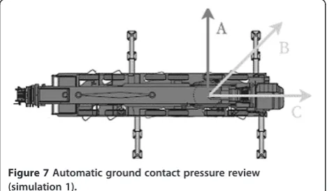
The simulation model for automatic stability review of ground contact stability is designed to review all MCs. As illustrated in Figure 7, the simulation model sets the installation location for all MCs and examines the ground contact pressure automatically by the simulation algo-rithms illustrated in Figure 7.
Table 1 Review items for ground contact stability
Step Items reviewed
Basic Items Review of the objects to be lifted Type, material and weight
Equipment Information Working radius, the maximum height of objects, crane weight and outrigger radius
Ground contact stability
Review of ground contact pressure Work direction, ratio of impact load and the maximum reaction of outrigger
Reinforcement of soil bearing force (flat site)
Plate type (steel, timber), rigidity of plate, soil bearing force, bending moment, and shearing force acting on plate
Reinforcement of soil bearing force (slopping site)
Additional data including slope data such as slopping angle, slopping length, slopping height, and distributed load on soil
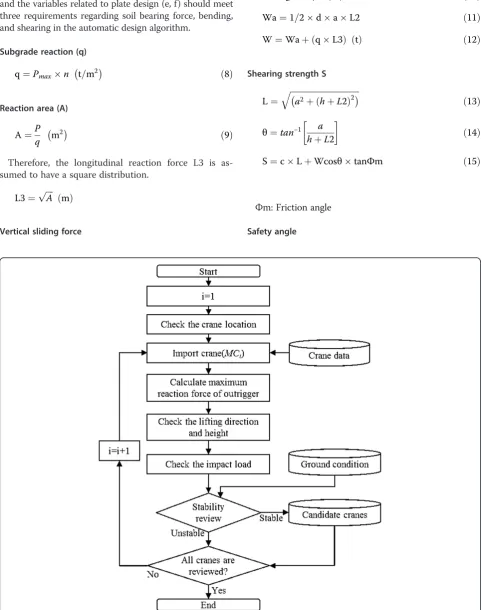
The ground contact pressure is reviewed in the order of the maximum reaction of the outrigger, the working direc-tion and height, and the impact load. The impact load value that is reviewed shows stability through a comparison with the ground conditions. Cranes that are regarded as stable are classified and saved automatically as the candidate
cranes. When all cranes have been reviewed, the simulation examining the ground contact pressure ends.
Reinforcement of Soil Bearing Force (flat site)
After the review of ground contract pressure, the stability of soil bearing force reinforcement should be reviewed to Figure 3The working radius and height of a mobile crane.
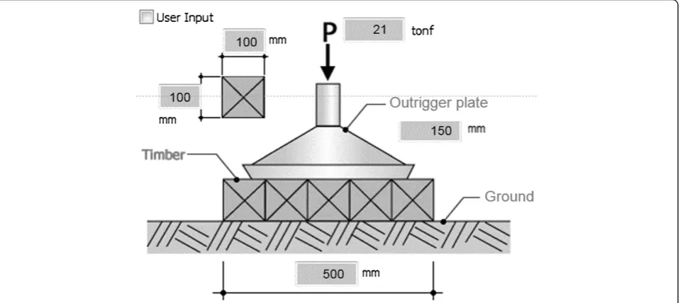
prevent overturn. The reinforcement of soil bearing force is reviewed under 2 different ground conditions: a flat and a slopping site. For the flat site, the plate material, thick-ness, and area should be reviewed manually by the user as shown in Figure 8 or automatically by the simulation algo-rithm as shown in Figure 9. Since the plate transfers the ground contact load of the outrigger to the ground, it should be designed after checking the adhesive power and the rigidity of the plate. The plate is usually made of tim-ber and steel, and data including bending and shearing ac-cording to the thickness and area should be gathered to be automatically applied to the simulation.
As shown in Figure 10 the generation model of soil bearing force reinforcement as plate reinforcement im-ports the additional data on ground contact pressure of the outrigger stored in the system implemented by the proposed algorithms besides the basic information speci-fied in Table 1. Based on such data, the plate type, rigid-ity, bearing soil force, and bending and shearing factors are automatically reviewed for reinforcement of soil bearing
force. When the plate fails to transfer the ground contact load to the ground, the crane is likely to overturn. For a slope, the soil type, soil property value and slope informa-tion should also be examined. When stability reviews of all items are completed, the crane and the suitable plate design are saved in pairs.
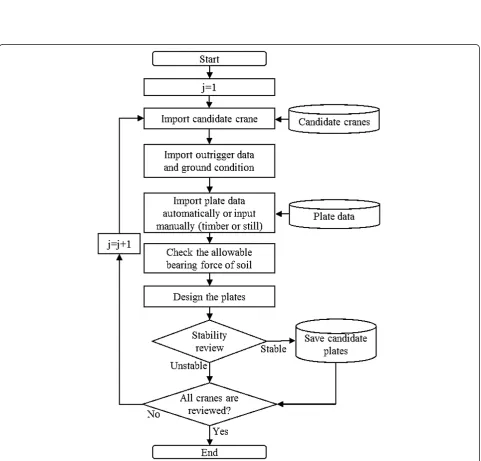
The automatic plate design for reinforcement of the soil bearing force on a flat site is applied with information like the outrigger of the candidate cranes drawn from simula-tion 1 as shown in Figure 7 and the body weight. For the plate design in simulation 2, the outrigger of a crane as shown in Figure 9 is selected, and the plate materials and allowable soil bearing force are checked for the design of the materials. The designed plate and the crane are saved in pairs within the scope that stability is secured. Simula-tion 2 is completed when all the candidate cranes deduced from simulation 1 are reviewed.
As demonstrated in Figure 11, the program automatic-ally reviews the plate design for reinforcement of soil bear-ing force on a flat site. The rigidity of plates by type and size is imported from the gathered data, and the max-imum ground contact load of the outrigger is inserted based on the result of simulation 1. Also, the crane weight and lifting capacity imported from the crane data are inserted. The values are saved after the soil bearing force and the plate’s bending and shearing are reviewed.
The plate for reinforcement of soil bearing force on a flat site is divided into timber and steel for the design de-pending on the material used, and the soil bearing force, Figure 5Generation model for ground contact stability review.
Figure 6Input page of crane information.
bending, and shearing should be automatically reviewed by the equations (3) to (7). Steel plate review items can be described as follows (Shapiro et al. 2000). Figure 11 shows the variables related to plate design (a, b, c, and t), which should meet the three requirements regarding soil bearing force, bending, and shearing in the automatic design algorithm.
Soil bearing force review
q¼ P
bc≤qa−−−−−−−O:K ð3Þ
P: Maximum Reaction,
qa: Allowable Soil Bearing Force
Bending review
M¼qba 2
2
f1¼3qa1 2
t2 ≤fb−−−−−−−O:K ð4Þ
f2¼3qa2 2
t2 ≤fb−−−−−−O:K ð5Þ
M: bending Moment,
f1: Transversal Bending Stress, f2: Longitudinal Bending Stress, fb: Allowable Bending Stress, a1: Transversal Direction a, a2: Longitudinal Direction a, t: Thickness of member
Shearing review
v1¼1:5qa1
t ≤fs−−−−−−−−O:K ð6Þ
v2¼1:5qa2
t ≤fs−−−−−−−O:K ð7Þ
v1: Transversal, horizontal shear stress v2: Longitudinal, horizontal shear stress, fs: Allowable shear stress of member
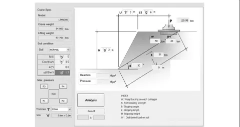
Reinforcement of Soil Bearing Force (slopping site) For the reinforcement of the soil bearing force of a slope, an additional review of the slope shape and the soil property value is required. As shown in Figure 12, the reinforcement plate is designed after reviewing the vertical weight, shearing strength, sliding angle, slope length, and height. The reinforcement plate installed on a slope should consider not only the transfer of load, but also the landslide at the slope.
The plate for reinforcement of the soil bearing force on a slope requires reviews of soil bearing force, bending, and shearing. Steel plate review items are described as follows (Shapiro et al. 2000). Figure 11 shows the variables related Figure 8Design of a reinforcement plate (flat site).
to plate design and slope shape (a, b, c, d, e, f, g, h, and t), and the variables related to plate design (e, f) should meet three requirements regarding soil bearing force, bending, and shearing in the automatic design algorithm.
Subgrade reaction (q)
q¼Pmaxn t=m2 ð8Þ
Reaction area (A)
A¼P
q m2 ð9Þ
Therefore, the longitudinal reaction force L3 is as-sumed to have a square distribution.
L3¼pffiffiffiffiA ð Þm
Vertical sliding force
L2¼gþL3=2 mð Þ ð10Þ
Wa¼1=2daL2 ð11Þ
W¼WaþðqL3Þ ð Þt ð12Þ
Shearing strength S
L¼
ffiffiffiffiffiffiffiffiffiffiffiffiffiffiffiffiffiffiffiffiffiffiffiffiffiffiffiffiffiffiffiffiffiffi
a2þðhþL2Þ2
q
ð13Þ
θ¼tan−1 a
hþL2
ð14Þ
S¼cLþWcosθtanΦm ð15Þ
Φm: Friction angle
Safety angle
Figure 11Plate design information (flat site).
Fa¼ S
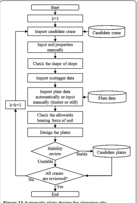
Wsinθ>1:2−−−−−−−O:K ð16Þ As illustrated in Figure 13, the plate design of a slope analyzes the candidate cranes deduced from simulation 1 as illustrated in Figure 7. In simulation 3, the plate is designed by checking the soil properties such as the N value, adhesive power, friction angle, and weight of unit volume that are input manually by the user as shown in Figure 12. Also, the slope shape is automatically ana-lyzed by the equations (8) to (16) to review both the soil bearing force of the soil/ground and the landslide. For the plate design in simulation 3, the outrigger of a crane as shown in Figure 13 is selected, and the plate materials and the allowable soil bearing force are checked for the design of the materials. The designed plate and the crane are saved in pairs within the scope that stability is se-cured. Simulation 3 is automatically completed when all the candidate cranes deduced from simulation 1 are reviewed.
The top level process for mobile crane plans is com-prised of 3 simulations, as illustrated in Figure 14. When
selecting mobile cranes (Figure 7), the project data and crane data are used to deduce the candidate cranes within the required ground contact pressure. It should be checked whether the mobile crane is available in the market, and the selected cranes become the basis for the plate design in simulation 2 or 3.
As previously described, only 1 type is simulated accord-ing to the ground shape for both simulations (2 & 3), and the plate suitable for the candidate crane is designed. The plate design is paired with the candidate crane for a review of economic feasibility, and is then finally selected.
This study proposes a model for selecting mobile cranes with the lowest cost possible, and designing plates by identifying multiple cases and calculating cost based on securing stability, which is the prerequisite. The objective variable of mobile crane and plate design is cost (Cmc). The objective function of this model is to minimize the sum of mobile crane rental cost (Crental) and plate cost (Cplate) as shown in Formula 17. The cost calculation of the model shown in Figure 14 is automatically carried out in 2 steps. First, a rental cost is calculated from the data of n candidate cranes. Second, respective cost is calculated for‘m’plates designed in simulations 2 and 3. The model aims to estimate the minimum cost, and the objective and constraint functions are as shown below.
Minimize Cf mcg ð17Þ
Cmc¼ Crentalþ Cplate
Figure 13Automatic plate design for slopping site (simulation 3).
Subject to:WRmc≥required working radius LCmc≥required lifting load
MIoutrigger≤allowable bearing force of soil SHplate≥shear force of plate
BEplate≥bending force of plate
WhereCmc: cost of mobile crane work Crental: rental cost of mobile crane Cplate: cost of designed plate
WRmc: working radius of selected mobile crane LCmc: lifting capacity of selected mobile crane MIoutrigger: maximum impact load of outrigger SHplate: allowable shear stress of designed plate BEplate: allowable bending stress of designed plate
Result and discussion
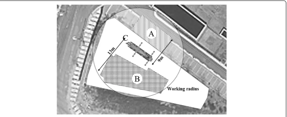
To verify the effectiveness of the automatic design model, a case project is selected and the algorithm is applied as-suming several conditions. Above all, the case project is a site where buildings are not completed, and it is assumed that PC members are to be installed on the first floor. C in Figure 15 is the location of a mobile crane, and A shows a material storage yard. B is the building to be constructed, and the distance between a crane and a building is around 13 m. The heaviest lifting object is the PC beam that is 8 m long, which weighs 4.6 tons. The total lifting weight considering sling and lug is 5.06 tons.
In consideration of lifting conditions such as the working radius and weight of lifting objects, 18 candidate cranes are selected in total. Ground contact pressure upon operation of each candidate crane is calculated, and allowable soil bearing force is set as 20 tf/m2 to design plates for reinforcement of soil bearing force.
As a result no information regarding self-weight, so they are not automatically designed. a, b, c, and t in Table 2 refer to the width, breadth and thickness of plates shown
in Figure 3. Ground contact pressure increases in the case of large cranes due to their self-weight, and they are de-signed with width and breadth of 2500 mm. This restricts the use of cranes. The smallest plate is designed with width of 1000 mm and thickness of 24 mm.
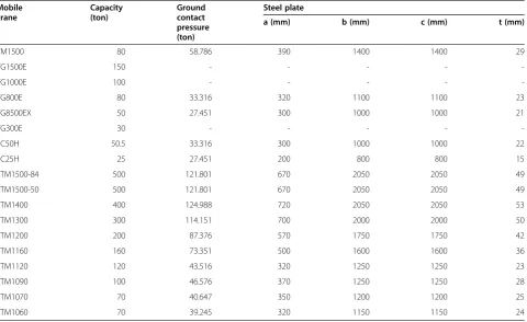
When the allowable soil bearing force is set as 30 tf/m2 under the same lifting conditions, plate design is as de-scribed in Table 3. Applicable crane types are the same, yet plate design has changed. Due to the difference in al-lowable soil bearing force, the plate for reinforcement of soil bearing force is designed with width and breadth of 800 mm and thickness of 15 mm. Thus, the specifications in Table 3 should be applied for reinforcement plates when using cranes to limit crane overturn risks.
Conclusion
This study develops automatic design algorithms for se-curing the ground contact stability of mobile cranes. In addition, the algorithms proposed in the study focus on the ground stability review process of mobile cranes. The study subjects are hydraulic cranes (or tire cranes), and single lifting is assumed for the study. Ground contact sta-bility is reviewed based on the installation of cranes on soil or ground.
The study results are as follows.
Firstly, we found that the database built using the available tower cranes in the market for automatic design of mobile cranes can easily and quickly select candidate cranes according to lifting conditions and design plates through simulations.
Table 2 Result of automatic design model (1)
Mobile crane
Capacity (ton)
Ground contact pressure (ton)
Steel plate
a (mm) b (mm) c (mm) t (mm)
TM1500 80 58.786 570 1750 1750 34
TG1500E 150 - - - -
-TG1000E 100 - - - -
-TG800E 80 33.316 420 1300 1300 26
TG8500EX 50 27.451 400 1200 1200 24
TG300E 30 - - - -
-SC50H 50.5 33.316 400 1200 1200 24
SC25H 25 27.451 300 1000 1000 18
LTM1500-84 500 121.801 900 2500 2500 54
LTM1500-50 500 121.801 900 2500 2500 54
LTM1400 400 124.988 900 2500 2500 54
LTM1300 300 114.151 900 2400 2400 54
LTM1200 200 87.376 750 2100 2100 45
LTM1160 160 73.351 670 1950 1950 40
LTM1120 120 43.516 450 1500 1500 27
LTM1090 100 46.576 520 1550 1550 31
LTM1070 70 40.647 470 1450 1450 28
LTM1060 70 39.245 470 1450 1450 28
Table 3 Result of automatic design model (2)
Mobile crane
Capacity (ton)
Ground contact pressure (ton)
Steel plate
a (mm) b (mm) c (mm) t (mm)
TM1500 80 58.786 390 1400 1400 29
TG1500E 150 - - - -
-TG1000E 100 - - - -
-TG800E 80 33.316 320 1100 1100 23
TG8500EX 50 27.451 300 1000 1000 21
TG300E 30 - - - -
-SC50H 50.5 33.316 300 1000 1000 22
SC25H 25 27.451 200 800 800 15
LTM1500-84 500 121.801 670 2050 2050 49
LTM1500-50 500 121.801 670 2050 2050 49
LTM1400 400 124.988 720 2050 2050 53
LTM1300 300 114.151 700 2000 2000 50
LTM1200 200 87.376 570 1750 1750 42
LTM1160 160 73.351 500 1600 1600 36
LTM1120 120 43.516 320 1250 1250 23
LTM1090 100 46.576 370 1250 1250 28
LTM1070 70 40.647 350 1200 1200 25
design plans from among those that satisfy stability review requirements after relevant costs are calculated.
Lastly, a plate design model connected to the selected mobile crane should first review ground contact pressure. It was found that system runtime is shortened when ground contact pressure to prevent overturn is reviewed before design.
The algorithms proposed in this study conduct simula-tions for all possible candidate cases, save the results in a database, review practical alternatives, and select the solution that minimizes cost. This is because stability is more important than economic feasibility when operating mobile cranes. Developed processes are useful for analyz-ing correlations of mobile crane performance, ground con-tact and soil bearing force reinforcement designs and so forth, and for systematically selecting optimal mobile cranes. Other studies should be conducted on stability re-view models of double lifting (where 2 mobile cranes are used). Furthermore, stability review models of components such as the sling and lug required for lifting must be devel-oped to prevent the fall of lifting objects.
Competing interests
The algorithms proposed in this paper demonstrate the review for securing the ground contact stability and the design of reinforcement plates automatically after a mobile crane selection. The case study was carried out to verify the effectiveness of the proposed algorithms.
Many researchers have conducted a wide range of studies about mobile cranes such as the implementation of a lifting rout plan program (Reddy and Koshy 2002; Lozano-Pérez and Wesley 1979) and a crane selection algorithm (Al-Hussein et al. 2001; Shapira and Schexnayder 1999; Al-Hussein et al. 1997; Furusaka and Gray 1984; Gray and Little 1985), the overturn analysis of outriggers (Tamate et al. 2005), the friction with other works (Tantisevi and Burcu 2007) and even the development of a dual lifting simulation program. However, they didn’t deal with a series of mobile crane management for securing both stability and economy, but dealt with the partial issue of it, whereas this paper covered the principal issues from selecting a proper crane responding to the lifting conditions to reviewing the stability of cranes automatically, followed by the economic design of reinforcement plates.
The case study of this paper illustrates the automatic reinforcement plate design for two cases of allowable soil bearing force. Site engineers can figure out the rental and plate costs of candidate cranes and, then, select the minimum cost for crane operation. A series of algorithms for mobile crane management was implemented to the software for practical use except the cost minimization algorithm that should be additionally equipped to the software for better use in practice.
Authors’contributions
DL and SK together carried out the filed study. Subsequently, the gathered data was analyzed. All authors contributed to develop the algorithms. All authors read and approved the final manuscript.
Acknowledgement
This work was supported by the National Research Foundation of Korea (NRF) grant funded by the Korea government (MSIP) (No.
2013R1A2A2A01068297).
Author details
1
Department of Architectural Engineering, Kyung Hee University, 1732 Deogyeong-dearo, Giheung-gu, Yongin-si, Gyeonggi-do, Korea.2Department of Q-HSE Management Division, Technical Advisory Team, Samsung C & T Corporation, Seocho2-Dong, Seocho-Gu Seoul 1321-20, Korea.
Received: 30 December 2013 Accepted: 7 June 2014
References
Al-Hussein, M, Alkass, S, & Osama, M. (1997). Computerized crane selection for construction projects.Journal of Construction Engineering Management, Association of Researchers in Construction Management, 2, 427–436. Al-Hussein, M, Alkass, S, & Osama, M. (2001). An algorithm for mobile crane
selection and location on construction sites.Construction Innovation: Information, Process, Management, 1(2), 91–105.
Furusaka, S, & Gray, C. (1984). A model for the selection of the optimum crane for construction sites.Construction Management and Economics, 2(2), 157–176. Gray, C, & Little, J. (1985). A systematic approach to the selection of an
appropriate crane for a construction site.Construction Management and Economics, 3(2), 121–144.
Ho, JK, Han, KK, & Kim, SK. (2007a). Tower crane foundation design and stability review model.Korea Institute of Ecological Architecture and Environment, 7(6), 99–106.
Ho, JK, Seo, JM, & Kim, SK. (2007b). Mobile crane ground fixing system.Korea Institute of Ecological Architecture and Environment, 7(6), 83–90. Kim, HH, & Lee, K. (2007). An analysis of the accident types and causes of
construction cranes.Korea Institute of Construction Engineering, 7(1), 109–112. Lin, KL, & Haas, CT. (1996). Multiple heavy lifts optimization.Journal of
Construction Engineering and Management, 122(4), 354–362.
Lozano-Pérez, T, & Wesley, MA. (1979). An algorithm for planning collision-free paths among polyhedral obstacles.Communications of the ACM, 22(10), 560–570. Maczynski, A, & Wojciech, S. (2003). Dynamics of a mobile crane and optimisation of
the slewing motion of its upper structur.Nonlinear Dynamics, 32(3), 259–290. Reddy, HR, & Koshy, V. (2002). Automated path planning for mobile crane lifts.
Computer-Aided Civil and Infrastructure Engineering, 17(6), 439–448. Shapira, A, & Schexnayder, CJ. (1999). Selection of mobile cranes for building
construction projects.Construction Management & Economics, 17(4), 519–527. Shapiro, HI, Shapiro, JP, Shapiro, LK, & Shapiro, HI. (2000).Cranes and Derricks.
New York: McGraw-Hill.
Struková, Z, & Ištvánik, M. (2011). Tools for mobile crane selecting and locating. International Review of Applied Sciences and Engineering, 2(1), 69–74. Tamate, S, Naoaki, S, & Toshiyuki, K. (2005). Analyses of instability in mobile cranes
due to ground penetration by outrigger.Journal of Construction Engineering and Management, 131(6), 689–704.
Tantisevi, K, & Burcu, A. (2007). Automated generation of workspace requirements of mobile crane operations to support conflict detection.Automation in Construction, 16(3), 262–276.
The Vertikal Press. (2014).Loader crane overturn in UK, vertikal.net, News article. http://www.vertikal.net/en/news/story/19261/.
doi:10.1186/s40327-014-0007-x
Cite this article as:Leeet al.:Automatic design algorithms for securing the ground contact stability of mobile cranes.Visualization in Engineering 20142:7.
Submit your manuscript to a
journal and benefi t from:
7 Convenient online submission
7 Rigorous peer review
7 Immediate publication on acceptance
7 Open access: articles freely available online
7 High visibility within the fi eld
7 Retaining the copyright to your article