R E S E A R C H A R T I C L E
Open Access
Accessibility evaluation system for site layout
planning
–
a tractor trailer example
Jacob Je-Chian Lin, Chi-En Yang, Wei-Han Hung and Shih-Chung Kang
*Abstract
Background:Accessibility is a critical issue in site planning. A good accessibility plan can avoid possible conflicts involving equipment and allows for smooth transportation during the entire project. It can also ensure that sufficient space is available so that all onsite equipment, such as trucks, cranes and excavators can be safely operated. In current practice, the evaluation of accessibility is done manually, relying heavily on the experience of the construction planners. However, the evaluation needs to deal with temporal and spatial information simultaneously, which make the manual evaluations very challenging.
Methods:This research develops a sandbox environment for construction planners. As tractor-trailers are usually critical in accessibility evaluations, the simulation specifically focuses on these two-section vehicles. Four major steps were involved: Step 1: deriving a generic tractor-trailer mathematical model allowing real-time, physics-based computer simulation; Step 2: digitalizing a 2D site plan to the 3D virtual environment; Step 3: developing evaluation methods for accessibility, considering both safety and operability; Step 4: visualizing the evaluation results. We implemented these four steps using Microsoft XNA (a game platform) and Nvidia PhysX (a game engine). An example case is presented which uses the sandbox environment to evaluate the accessibility of a construction site. Results:From the case study, we found that realistic visualizations and simulations provide solid references for construction planners. They are able to identify potential accessibility problems and unsafe situations in the sandbox environment and avoid them early on in the design and planning stages.
Conclusion:This paper proposed an innovative approach for evaluating accessibility during pre-construction site layout planning. It can present an intuitive and easily understood visualization result which clearly indicated the unsafe parts of the site layout plan.
Keywords:Accessibility; Site layout; Trailer truck; Physics-based simulation; Game engine
Background
Accessibility is one of the most important considerations in site layout planning. The routes of a construction site need to be designed to ensure smooth delivery of mate-rials, safe machine operation and relatively easy relocation of large objects on site. Site planning directly influences the construction progress and often impacts cost if there are any unforeseen conflicts (Su et al. 2012).
Although accessibility appears to be an intuitively important issue in construction site layout planning, it has not been well-researched thus far. In practice, the evaluation of accessibility is still done manually, relying
heavily on the experience of the construction planners (Tam & Tong 2003; Elbeltagi et al. 2004; Li et al. 2009). Daily meetings are held to deal with accessibility prob-lems in which the engineers discuss transportation paths and the location of heavy equipment and temporary facilities to ensure that none of the various processes will be in conflict with one another. Without an intuitive tool to evaluate the accessibility of the site, engineers evaluate the space they need by considering qualitative positions (Akinci et al. 2002), which could easily lead to accessibility problems. Conflicts are usually caused by an incorrect assessment of the space occupied by equipment and facilities. Sometimes newly constructed elements/ parts may need to be demolished to create a passage for
* Correspondence:[email protected]
Computer-Aided Engineering Group, Department of Civil Engineering, National Taiwan University, 188, Sec. 3, HsinHai Rd, Taipei 10668, Taiwan
other equipment, for example a concrete conveyor truck, to get to its designated area.
Traditional site layout planning is primarily concerned with the positioning, existence and timing of the tem-porary facilities that are used throughout the construc-tion project (Mawdesley & Al-Jibouri 2003), and the site layout planning problem can be dissected into the following sub-problems: (1) identifying the shape and size of the facilities to be laid out; (2) identifying the constraints between facilities; and (3) determining the relative positions of these facilities (Zouein et al. 2002). In order to study the space utilization of construction sites, research of site layout planning has been carried out and many studies have attempted to solve site layout planning problems. The research within this scope can be classified according to two different criteria: (1) opti-mization algorithms and (2) visualization.
Under the first criterion, researchers have used differ-ent kinds of optimization algorithms to solve site layout planning problems. Zouein et al. (2002) tried to resolve transportation cost problems in construction site layout planning by using genetic algorithm analysis. Mawdesley and Al-Jibouri (2003) used a genetic algorithm to reduce the costs associated with transportation paths, and both Lam et al. (2009) and Ning et al. (2010) combined the genetic algorithm and the Max-min Ant system (MMAS) to provide a computing method for reducing cost and transportation time. Wong et al. (2010) utilized genetic algorithms to optimize a layout for precast facil-ities on a construction site. One of the limitations of these algorithms is that some of them assume that all the facilities in the construction site can be represented by box shapes. Researchers have tried other approaches of developing automated optimization of site layout planning (Elbeltagi et al. 2001; Lam et al. 2007; Easa & Hossain 2008).
Under the second criterion, research involves the use of visualization for site layout planning. Sadeghpour et al. (2006) utilized computer-aided tools to analyze the appropriate location of the facilities, and simplified 2D visualization tools to analyze their geometric relation-ships. In terms of developing a site representation, the computer-aided tools approach has some similarity with the approach implemented in this research. Dawood and Marasini (2003) developed a simulation tool that visual-izes the construction site in 2D to help improve the plan. Ma et al. (2005) developed a 4D system which integrates schedules, 3D models, resources, and site spaces to provide a visualization of the plan. Sadeghpour (2006) used computer-aided tools to offer an intuitive understanding of the site layout by displaying shapes of temporary facilities through direct visualization of their positions. Benjaoran and Bhokha (2010) used a 4D computer-aided design (CAD) model to simulate the
construction process to ensure safety. In another research study, a pre-construction planning method was imple-mented by creating a virtual construction work package. This package can virtually rearrange 3D models to review the design for constructability (Waly & Thabet 2003).
In short, the majority of previous studies have focused on how to reduce the transportation costs of site layout planning. They utilized mathematical models and algo-rithms to compute the least distance between facilities. Thus, in current site layout planning methods, the loca-tion of facilities will be largely determined by consider-ations such as the distance to materials, the transportation time and the transportation cost (Hegazy & Elbeltagi 1999; Mawdesley et al. 2002; Tam et al. 2002; Zouein et al. 2002). Although these methods can generate a plan with paths of the least distance or lowest transportation costs, the accessibility issue is neglected. In a real site situation, the accessibility of transportation vehicles can directly affect the progress of work. If the transportation path is difficult to navigate due to obstacles or convoluted routes in a narrow working area, even if the distance is shorter, it can lower the efficiency of the operation. Further-more, it can occasionally cause additional damage and costs (Soltani et al. 2002).
On the other hand, drawbacks can also be found in research under the second category. This research may incorporate 3D modeling of construction elements but still not perform realistic simulations of mobile machin-ery, a factor that profoundly influences site layout per-formance. Since accidents involving transportation are one of the most frequently occurring types of accidents at a construction site (IOS & H 2012), safety and acces-sibility should be given more importance during the planning process and the designing of transportation paths, rather than restricting the considerations only to distance and cost (Thomas et al. 2005; Andayesh & Sadeghpour 2013).
Engineers can therefore easily identify the unsafe parts of a site and mitigate potential accessibility problems.
Research goals
In this research, we developed an accessibility evaluation system for site layout planning. Because tractor-trailers are usually critical in accessibility evaluations, we have specifically focused the simulation on these two-section vehicles. The system can facilitate the achievement of the following goals:
1. The simulation of transportation in an interactive, realistic virtual environment. From this, users can directly simulate transportation process to identify potential safety and accessibility problems under various situations and different site layout plans. 2. The development of an evaluation method for site
accessibility. Via the proposed system, users can test their planned site layout and evaluate its accessibility and safety. After evaluation, the proposed system can support a visualized output of the evaluated result to help engineers understand the unsafe areas of the site layout, and therefore being able to work out a lower cost, safer, and improved plan. 3. The importing of the map of the construction site
and the building up of the virtual environment of the construction site in a fast and efficient way.
Methods
Accessibility evaluation system
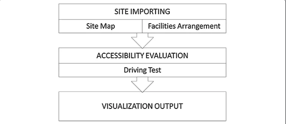
We developed an accessibility evaluation system, which consists of four modules (Figure 1). The transportation module simulates the dynamic motion of a tractor-trailer by using multi-body dynamics, a method commonly used
for game physics. The site importing module enables users to generate the construction site environment precisely and efficiently from a 2D blueprint or image file of a construction site. The safety evaluation module is used to evaluate the site’s accessibility by adding a multi-layer collision boundary to the transport unit, which detects collisions between the boundary of each layer and obstacles at the site. A formula was then developed for assessing the accessibility of each divided area at the site. The visualization module is used to render the virtual construction site and simulate the transportation activities (i.e. detailed motions of the trailer) taking place there.
Transportation module
The transportation module aims to provide engineers with a real-time interactive system for operating the tractor-trailer in a virtual environment so that problems in the transport process can be discovered efficiently. We used a tractor-trailer, a commonly used transport vehicle in construction, as the transport unit. It has been observed that the most commonly occurring accessibility problems involve tractor-trailers. The tractor-trailer is hard to control because the driver needs to take care of the trailer, and it also has more blind spots than a single unit vehicle. If an entrance or road is not well designed, the tractor-trailer can very easily become stuck. This kind of situation can be prevented by improved accessi-bility simulation.
The tractor-trailer is the most complicated machine to simulate as it has the most degrees of freedom of all mobile construction machinery. Mobile construction machinery can be classified into three different types: wheel, track, and chain. The wheel type includes typical construction machinery such as a truck. The track type
refers more to heavy construction machinery such as an excavator. The chain type consists of multiple rigid bodies and connections such as a tractor-trailer. The chain type is the most complicated because its motion has the most degrees of freedom. Once the accessibility method for simulating the tractor-trailer is established, the user can easily apply it to other kinds of mobile construction machinery. A tractor-trailer is composed of multiple rigid bodies and connections. Mathematical equations can be used to represent the relationships between the connections of rigid bodies, which are controlled by the rules of physics. We used the concept of multi-body dynamics, which are commonly used for simulating and modeling the dynamic motions of articu-lated mechanisms or equipment (Hung & Kang 2009). We also provided a mathematical model to compare with the developed model to verify its feasibility.
Tractor-trailer model using multi-body dynamics
Multi-body dynamics is mainly used for computing physical feedback between multiple bodies in mutual contact with each other or connected to each other by joints (Erleben 2005). The simulation of multi-body dynamics is generally composed of rigid body dynamics and constraints. By solving the equations of motion (which are used to describe the dynamic behavior of multi-body dynamics), the simulation can calculate the behavior of a multi-body during each time integration (Hung & Kang 2009).
In this study, the rigid bodies in the tractor-trailer are called actors (for example, the bodies that steer the wheels of a car). The type ofJointdetermines the motion between a pair of rigid bodies within the entire multi-body. The basic joint used in this paper is the revolute joint, which attaches two actors by a hinge-like struc-ture. It only has one degree of freedom of rotation so that the two actors can only rotate on one axis (Hung & Kang 2009).
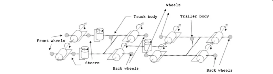
A tractor-trailer can be separated into two main parts: the tractor and the trailer. The trailer connects to a
fill-up tank. To build the tractor-trailer model, the locations of the wheels, tractor, trailer, and fill-up tank must be analyzed and connected correctly. In this paper, the tractor-trailer is simulated as an eight-wheel truck, with four wheels on the tractor and four wheels on the trailer. The construction of the tractor and trailer is similar: revolute joints connect the wheels to the steers and also the steers to the main body of the truck. The only differ-ence between the tractor and trailer is that the trailer is connected to the fill-up tank by another revolute joint. Figure 2 shows the developed model represented by symbols as defined in previous research.
Tractor-trailer mathematical model
The mathematical model of the tractor-trailer is con-structed based on a previous study by Rouchon and Fliess (1993) and is governed by the following equations:
ẋ0¼ cosð Þθ0 u1 ð1Þ
y
̇
0¼ sinð Þθ0 u1 ð2Þ
φ̇ ¼u2 ð3Þ
θ0
̇ ¼ 1
d0
tanð Þφ u1;for i¼1;……;n ð4Þ
θi
̇ ¼ 1
di ∏ i−1
j¼1cos θj−1−θj
sinðθi−1−θiÞu1 ð5Þ
In these equations, (x0, y0,φ,θ0,θ1…θn)∈R2× (S1)n+2
represents the tractor-trailer state, where (x0, y0) are the
coordinates of the head and φ is the steering angle. The heading of the truck isϴ0and the angle of the trailer is ϴ1, both with respect to the x-axis. ‘u1’ and ‘u2’are the
velocity control factors, where‘u1’is the driving speed and
‘u2’ is the angular velocity of the steering angle. ‘d’
re-presents the distance between trailers and is a positive constant (Rouchon and Fliess 1993). Figure 3 shows a representation of these variables. Using these equations, we can derive the mathematical relationship between the tractor and trailer and program it into the simulation
engine. We used this approach to simulate the construc-tion tractor-trailer for comparison with our developed model.
Comparison between the two models
The result of the mathematical model simulation is used to verify the model developed in this research. Each simu-lation used the same degree of turning and velocity so that the trajectory of the tractor-trailer would be a circle. The differences between the two models under different de-grees of turning and velocities were then compared.
Motion trajectory
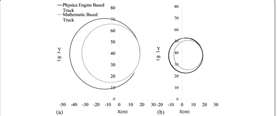
In Figure 4, the velocity and turning degrees are set to the same value for the two models. One turning degree is set at 6°, and the other at 12°. We discovered that the lower the turning degree, the greater the motion trajec-tory radius, with the difference and error between the two models becoming greater; in other words, the higher
the turning degree, the lower the motion trajectory and the smaller the error between the two models.
Motion trajectory with time
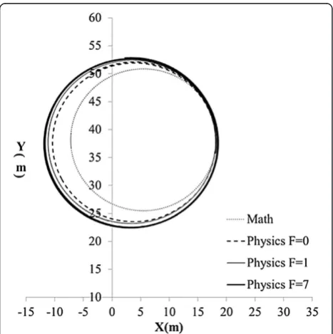
In this section, we describe the impact of the addition of the time factor. The comparison results are shown in Figure 5 and they demonstrate that error accumulates as time increases. The possible reasons for this error are discussed in the following section.
Sources of error
The mathematical model is constructed in a very simpli-fied manner. It ignores the friction between the wheels and the ground (Figure 6). On the other hand, the phys-ics engine enhances the contribution of the behavior between the tractor-trailer and the environment to its ultimate trajectory. Hence, there will necessarily be some differences between the two models. However, since the extent of error is acceptable we can conclude that the
Figure 3The Mathematical tractor-trailer model is developed based on the research of (Rouchon & Fliess 1993).
physics model is acting similarly to the mathematics model, and, considering the greater number of factors it considers, it can be conjectured that it models the behavior even more accurately.
Summary
Our aim was to create a tractor-trailer model that approximated real-world behavior. The mathematical model was built based on a previous study, whereas the physics-based model was built using “multi-body dyna-mics”, an approach not yet taken in any other research. The comparison of the physics model and the mathe-matical model leads to the following conclusions: (1) the mathematical model generates the ideal behavior of the tractor-trailer and the physics-based model behaves in a
similar manner; (2) The mathematical model is easier to build and consumes less computational resources; (3) Accumulated error related to friction is present in the physics model and therefore when the proper friction coefficient is applied, the physics model can generate more realistic behavior than the mathematical model; and (4) Collision boundaries can be directly incorpo-rated into the physics model whereas they can only be appended onto the mathematic model, and as a result the physics model is the more desirable model for use in site plan evaluations.
Site importing module
To begin the evaluation the virtual environment of the construction site has to be generated and it must be pre-cise in its dimensions and include all possible obstacles along the transportation routes to ensure that the safety test will be realistic. Since the facilities at the site are changeable during construction, the procedure of site environment generation must also be efficient and auto-matic. This can then allow engineers to test several layout plans in a fast manner.
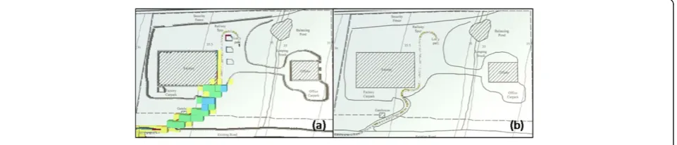
To achieve this goal we developed a site importing module which uses the 2D image of the site plan as the input data for generating the virtual construction site, which includes collision checking. Users should manu-ally modify the plan image to a specific scale and then highlight every obstacle with a specific color, which will then be recognized by the system. The system will then render an obstacle at a default size at each highlighted location. Figure 7 shows an example of modifying a 2D site plan. In this case, the site’s dimensions are approxi-mately 400 meters in width and 300 meters in height. The resolution was set so that one pixel represented one square meter, and so the 2D plan was converted to 400 pixels in width and 300 pixels in height, being a rather small scale for the modification process. During this process, only necessary boundaries are kept while others are deleted. In the case of Figure 7(b), there are permanent
Figure 5The motion trajectory co-ordinates versus time for the two models. (a)With 6 degrees of turning and(b)12 degrees of turning.
facilities such as the factory and office, an existing road, and the walls or fences of the entire site.
The site importing module described takes 2D images of the site plan as input data. The scope of this research did not include an in-depth look at the impact of differ-ing object heights in order to simplify the input process and facilitate computation. The system simply generated columns with a default height to represent the obstacles and boundaries appearing on the site.
Accessibility evaluation module
After the virtual construction environment is built, the accessibility evaluation can commence. In this module, the safety level of the transportation route is numerically assessed. An index, Safety Factor (SF), is developed to evaluate the site layout by integrating three different safety parameters. Detailed concepts relating to each safety parameter will be discussed in the following sections.
Safe driving range
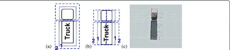
The safety range of the driving paths for transportation was evaluated by adding a multi-layer collision boundary (Safety Bound) to the transport unit, which detected any collision between the boundary of each layer and obsta-cles on the site. The safety range score,li, was developed
to quantify this factor. There are three layers of safety
bounds as shown in Figure 8(a). Whenever an obstacle runs into a safety bound, it will gain a safety range score according to the level it touches and the maximum value will be kept. If no bound is touched, then the score will be zero.
Narrow level of route
If a route is narrow, there will be obstacles close to the transport unit on both the left and right hand sides. By separating the multi-layer collision boundary into two parts, we can evaluate the degree of the narrowness of the route. Narrow level, ni, quantifies this factor. There
are four collision boundaries as shown in Figure 8(b). Whenever an obstacle runs into a collision boundary, it will gain a narrow level score according to the level it touches and the maximum value will be kept. Otherwise, the score will be zero.
Curvature of route
If a route is tortuous, more driving skills are required than for driving on a straight route. Therefore, we take the curvature of the route into consideration. The In-stant curvatureof each segment of the route is evaluated while the transport unit is in motion. The curvature score, ci, which is computed at every time step of the test, is also recorded whenever an obstacle touches one of the safety bounds.
Figure 7Import necessary obstacles by modifying a 2D plan. (a)Original site image;(b)processed image; and(c)virtual construction site environment built by the processed image.
The safety factor
To execute a safety test for a route, the user needs to drive the tractor-trailer through a desired route, and can repeat this several times in order to test several possible driving conditions. After that, each unit obstacle gains a safety score,si, which integrates the three safety
parame-ters (curvature scoreci, narrow levelni, and safety range
score li) according to the formula shown in Equation 6.
We have adjusted these factors to be between 10-2and 10-1 by multiplying them by a weight. In this case, the weight value for C was ten because the value of cur-vature lay mostly between 10-2 and 10-1 and would otherwise be too small to be of significance. For N and L, 1/4 and 1/3 were used respectively in order to diminish the value to between 10-2and 10-1. The value ofα,βandγ was determined by the relative importance of user cogni-tion and the project type.
In this researchα=12,β= 4 andγ=7. These values have been tested by the authors and represented the most significant safety factor value of the construction site. This value is most suitable for construction sites that are more congested and have narrower corners. The value of the weights for each factor depends on the environment of the construction site and the type of transportation vehicle, and so it should be modified as required by engineers.
To turn safety scores into a practical guide for safety evaluation, users can select a certain resolution for the summing up of safety scores in an area. For example, if the chosen resolution is 10 m × 10 m, each divided area will gain a SF by summing up every safety score available within its 100 m2scope as shown in Equation 7.
si¼ðα10ciÞ þ βni 4
þ γli 3
ð6Þ
SF¼∑isi ð7Þ
Visualization module
The visualization module was designed for visualizing the evaluation results. This module provides a direct and brief method for engineers to quickly check through the evaluation result using visualization rather than having
to interpret numerical data. After the evaluation, SF will be presented by the height of a rectangular column situated on each divided area, as shown in Figure 9(a). Engineers can thus gain a broad understanding of the results from a quick glance. In addition, the complete trajectory of the tractor-trailer can be stored and rendered again if required, as shown in Figure 9(b).
Implementation
To implement the proposed system, we used the physics-based simulation engine developed by Hung and Kang (Hung & Kang 2009), which integrates Microsoft XNA and NVIDIA PhysX. XNA is a rende-ring engine used to generate consecutive images from 3D models in real-time. It also provides a basic game development environment such as handling user in-puts and audio playing. PhysX is a physics engine, which calculates the behavior of objects in the virtual environment. PhysX utilizes position-based dynamics to simplify and approximate multi-body dynamics, which is a stable and efficient method allowing the behavior to be simulated in real-time. It is also used to compute the collision detection in the accessibility evaluation module.
The procedure for using this system is as follows. Before executing the system, the user should load the 2D plan of the target site into the “site importing mod-ule”so that the system can generate the virtual obstacles. In addition, the user should set the initial position of the transportation unit according to the evaluation scenery. Next, the user launches the system and directs the model along the desired routes; the system will automat-ically record the safety factors. We used the Xbox360 gamepad as the default device for users to control the transport unit in the virtual environment. After reaching the end of the route, the user can switch to different evaluation modes provided by the“visualization module” and also export evaluation data for further use.
Results and discussion
Example case
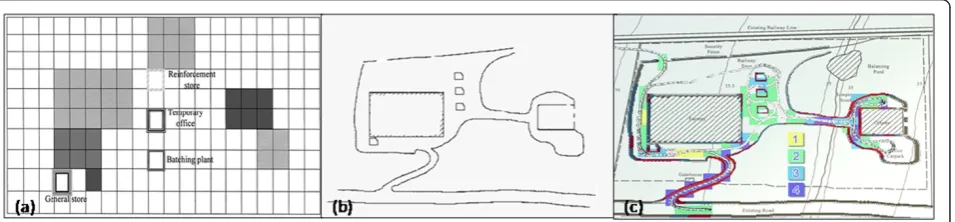
A preliminary example case was constructed to test the proposed evaluation system. We utilized the actual site
layout data of a previous site planning study by Mawdesley et al. (2002) as shown in Figure 7(a). There are permanent facilities in this construction site, such as the factory, lorry, park, and office. The goal of site planning is to determine the location of temporary facilities, including the rein-forcement store, temporary office and batching plant. First, we modified the construction site plan by adding possible locations of temporary facilities according to results obtained by Mawdesley et al. (2002), as shown in Figure 10(a) and (b). Then, the 2D site layout image was sent into the site importing module to generate the colli-sion boundary of the virtual environment. The feasibility of the proposed site layout plan was then evaluated. When the evaluation process was finished, the result was then visualized by the visualization module as shown in Figure 10(c). It clearly indicates the relative safety levels of each area and engineers can then re-plan or modify the unsafe areas accordingly. If the site is small, truck ope-rators can use the simulation system to rehearse the operation around those critical parts, which can reduce unexpected accidents or costs caused by accessibility problems.
The advantages of using this method can be summa-rized as follows: (1) the construction site is visualized so that during the evaluation process the user can clearly see accessibility problems; (2) the evaluation result is visualized so that the user can easily tell which part of the construction site needs to be modified; (3) the com-putational method is parametric and the parameters can be changed according to the circumstances of a specific site. The disadvantages of this method are as follows: (1) the user needs to decide the route first, and then eva-luate; (2) the construction of the virtual construction site takes time.
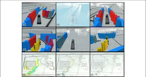
Figure 11 shows snapshots of the evaluation process using the developed system: (a) shows the tractor-trailer as it prepares to enter the site through the entrance; (b) is the physics mode, which visualizes the physically effective elements in the virtual environment; (c) is the combined view of the physics mode and normal mode, in this mode, we can clearly see that the obstacle changes
color when it comes into contact with different levels of the safety bound; (d) shows the visualization of the curvature score using yellow columns (it can be seen that the scores are relatively large around sharp turns); (e) shows a wide area resulting in a narrow level of zero; (f) is a return trip of the tested route; (g) is a top view of the visualization re-sult, whereby the color and height of the columns indicate the value of the Safety Factor at each location; (h) is the curvature modewhich shows the curvature score columns; and (i) istrajectory modewhich enables visualization of the trajectory of the tractor-trailer during the entire test.
Benefits
The developed accessibility evaluation system is expec-ted to greatly improve the planning of construction site layouts. The benefits are summarized as follows:
Construction sector workers all over the world are very vulnerable to accidents and physical injury. The system helps to calculate the use of safety zones around the boundaries of moving vehicles in construction areas which makes incorporating safety into site layout planning much more realistic.
The system vividly demonstrates the collision detection process of a moving vehicle, which makes the conflicts clearly visible. This can help poorly educated or illiterate operators be aware of safe driving/operating systems without having to read manuals or operation specifications.
The system can facilitate the accommodation of changeable issues regarding Health and Safety of the workforce, transport management, power
distribution, water supply and utility services, material storage, deployment and consumption at variously scheduled intervals allowing operational requirements from a variety of perspectives to be evaluated. Thus, it can provide managers with IT support and sophisticated information for making valuable decisions.
The system can facilitate the use of spaces for temporary facilities during a designated time
window to help relieve congestion of operations at site.
The optimum level of exposure for a moving truck can be recognized through color detection. Therefore, the optimal position of the object can be established for strategic areas.
Analyzing the closeness of objects, it helps in optimizing the positioning and the duration of the activities of certain expensive machine operations. The closeness of the objects can be analyzed by an evaluation of theSafe Driving Rangesafety parameter.
The system can help to identify problems regarding the changing of site layouts at different phases of construction. Thus, it can help analyze and control the sequence and priority of different phases of work to obtain a high cost-time productivity. During different phases, the user can try to evaluate the accessibility of the site layout.
It helps to identify the minimum space required to support specific construction operations in
restricted space or congested areas, thus improving the welfare of workers and pedestrians. Because the accessibility of the tractor-trailer can affect the space of other operations, the user can understand the required space of operations by the accessibility evaluation of the site.
The modeled method helps engineers progress from an“experience-based”to a“computation–based” accessibility evaluation, which will make it easier to identify potential problems.
Conclusions
This paper proposed an innovative approach for evaluating accessibility during pre-construction site layout planning. A 3D simulation platform was developed for the verification of the feasibility of a site layout plan. In this system, a phy-sics engine was used to capture the motion and reaction of the objects in the environment in order to approximate real world conditions. To allow work on different planning cases to be carried out efficiently, a site importing module was designed. The visualization module features the advan-tage of virtual reality, providing engineers with an easy way to check evaluation results and improve current site plan-ning proposals. This paper described an example case using the proposed system to evaluate the safety and accessibility of an actual site layout plan. The evaluation result pre-sented an intuitive and easily understood visualization which clearly indicated the unsafe parts of the site layout plan. The example case results show that the proposed sys-tem has the potential to reduce the costs caused by trans-portation accessibility problems.
The same modeling method used for the tractor-trailer can be applied to different kinds of construction machinery
Figure 11Snapshots of the evaluation process in the developed system. (a)-(c)The basic three viewing modes of the system;(d)-(f)
and future research will be directed towards this end so that the developed accessibility evaluation method can be used. The major limitation of this research is that the method has only been tested by one example case, and al-though it is a relatively complicated scenario, the method must be applied to more construction sites to validate its effectiveness more conclusively. Furthermore, by applying the method to more cases, the user can also identify more safety factors that can be included in the safety score. The system provides a realistic interactive environment for users in which they may simulate any possible route of the tractor-trailer. In future work, the route could be decided automatically by applying a motion planning algorithm.
Competing interest
The authors declare that they have no competing interests.
Authors’contribution
JCL and CEY co-developed the accessibility evaluation system and contributed evenly to the whole study and manuscript writing. WHH developed the simulation environment implementing multi-body dynamics in his previous research, and was included as the basis of this study. SCK was the adviser and proof-read the article. All authors read and approved the final manuscript.
Received: 6 May 2013 Accepted: 4 November 2013 Published: 9 December 2013
References
Akinci, B, Fischer, M, et al. (2002). Automated generation of work spaces required by construction activities.Journal of Construction Engineering and Management-Asce, 128(4), 306–315.
Andayesh, M, & Sadeghpour, F. (2013). Dynamic site layout planning through minimization of total potential energy.Automation in Construction, 31, 92–102.
Benjaoran, V, & Bhokha, S. (2010). An integrated safety management with construction management using 4D CAD model.Safety Science, 48(3), 395– 403.
Dawood, N, & Marasini, R. (2003). Visualisation of a stockyard layout simulator
“SimStock”: a case study in precast concrete products industry.Automation in Construction, 12(2), 113–122.
Easa, S, & Hossain, K. (2008). New Mathematical Optimization Model for Construction Site Layout.Journal of Construction Engineering and Management, 134(8), 653–662.
Elbeltagi, E, Hegazy, T, et al. (2004). Dynamic Layout of Construction Temporary Facilities Considering Safety.Journal of Construction Engineering and Management, 130(4), 534–541.
Elbeltagi, E, Hegazy, T, et al. (2001). Schedule-dependent evolution of site layout planning.Construction Management and Economics, 19(7), 689–697. Erleben, K. (2005).Physics-based animation. Hingham: Mass., Charles River Media. Hegazy, T, & Elbeltagi, E. (1999). EvoSite: Evolution-based model for site layout
planning.Journal of Computing in Civil Engineering, 13(3), 198–206. Hung, WH, & Kang, SC. (2009).Physics-Based Crane Model for the Simulation of
Cooperative Erections(p. 11). Sydney: 9th International Conference on Construction Applications of Virtual Reality.
IOS&H. (2012).Construction Industry Accidents Knowledge Platform. http://www.iosh.gov.tw/CIAKP/Statistics2.aspx.
Lam, KC, Ning, X, et al. (2009). Conjoining MMAS to GA to Solve Construction Site Layout Planning Problem.Journal of Construction Engineering and
Management-Asce, 135(10), 1049–1057.
Lam, KC, Ning, X, et al. (2007). The application of the ant colony optimization algorithm to the construction site layout planning problem.Construction
Management and Economics, 25(4), 359–374.
Li, H, Chan, N, et al. (2009). Optimizing construction planning schedules by virtual prototyping enabled resource analysis.Automation in Construction, 18(7), 912–918.
Ma, Z, Shen, Q, et al. (2005). Application of 4D for dynamic site layout and management of construction projects.Automation in Construction, 14(3), 369–381.
Mawdesley, MJ, & Al-Jibouri, SH. (2003). Proposed genetic algorithms for construction site layout.Engineering Applications of Artificial Intelligence, 16(5–6), 501–509.
Mawdesley, MJ, Al-jibouri, SH, et al. (2002). Genetic algorithms for construction site layout in project planning.Journal of Construction Engineering and Management, 128(5), 418–426.
Ning, X, Lam, KC, et al. (2010). Dynamic construction site layout planning using max-min ant system.Automation in Construction, 19(1), 55–65.
Rouchon, P, & Fliess, M. (1993).Flatness, motion planning and trailer systems (pp. 2700–2705). San Antonio, Texas, U.S.A: Proceedings of the 32nd IEEE Conference on Decision and Control.
Sadeghpour, F, Moselhi, O, et al. (2006). Computer-aided site layout planning. Journal of Construction Engineering and Management-Asce, 132(2), 143–151. Soltani, AR, Tawfik, H, et al. (2002). Path planning in construction sites:
performance evaluation of the Dijkstra, A∗, and GA search algorithms. Advanced Engineering Informatics, 16(4), 291–303.
Su, X, Andoh, AR, et al. (2012). GIS-based dynamic construction site material layout evaluation for building renovation projects.Automation in Construction, 27, 40–49.
Tam, CM, & Tong, TKL. (2003). GA-ANN model for optimizing the locations of tower crane and supply points for high-rise public housing construction.
Construction Management and Economics, 21(3), 257–266.
Tam, CM, Tong, TKL, et al. (2002). Site layout planning using nonstructural fuzzy decision support system.Journal of Construction Engineering and Management, 128(3), 220–231.
Thomas, HR, Riley, DR, et al. (2005). Fundamental principles of site material management.Journal of Construction Engineering and Management, 131(7), 808–815.
Waly, AF, & Thabet, WY. (2003). A Virtual Construction Environment for preconstruction planning.Automation in Construction, 12(2), 139–154. Winch, G, & North, S. (2006). Critical Space Analysis.Journal of Construction
Engineering and Management, 132(5), 473–481.
Wong, CK, Fung, IWH, et al. (2010). Comparison of Using Mixed-Integer Programming and Genetic Algorithms for Construction Site Facility Layout Planning.Journal of Construction Engineering and Management-Asce, 136(10), 1116–1128.
Zouein, PP, Harmanani, H, et al. (2002). Genetic algorithm for solving site layout problem with unequal-size and constrained facilities.Journal of Computing in Civil Engineering, 16(2), 143–151.
doi:10.1186/2213-7459-1-12
Cite this article as:Linet al.:Accessibility evaluation system for site layout planning–a tractor trailer example.Visualization in Engineering
20131:12.
Submit your manuscript to a
journal and benefi t from:
7 Convenient online submission
7 Rigorous peer review
7 Immediate publication on acceptance
7 Open access: articles freely available online
7 High visibility within the fi eld
7 Retaining the copyright to your article