Volume 2009, Article ID 539713,15pages doi:10.1155/2009/539713
Research Article
Multichannel Texture Segmentation Using Bamberger Pyramids
Jose Gerardo Rosiles
1and Mark J. T. Smith
21Electrical and Computer Engineering Department, The University of Texas at El Paso, 500 W. University Avenue, El Paso,
TX 79968-0523, USA
2Electrical and Computer Engineering Department, Purdue University, Electrical Engineering Building, 465 Northwestern Avenue,
West Lafayette, IN 47907-2035, USA
Correspondence should be addressed to Jose Gerardo Rosiles,[email protected]
Received 6 November 2008; Revised 30 May 2009; Accepted 5 August 2009
Recommended by Andreas Uhl
A multichannel texture segmentation algorithm is presented based on the image pyramids produced with the Bamberger directional filter bank. An extensive evaluation of Bamberger pyramids and their design parameters is presented. The impact on segmentation performance of factors like the number of pyramid levels, number of directional channels, redundancy and filter specifications is considered. The proposed system is shown to provide some of the best results reported to date when compared with other multichannel representations under similar evaluation conditions. It is further shown that segmentation results using the maximally decimated directional filter bank rival those of the undecimated case. To the knowledge of the authors, such performance has not been previously observed for decompositions with decimated channels.
Copyright © 2009 J. G. Rosiles and M. J. T. Smith. This is an open access article distributed under the Creative Commons Attribution License, which permits unrestricted use, distribution, and reproduction in any medium, provided the original work is properly cited.
1. Introduction
Image segmentation has received considerable attention over the last few decades. The goal of segmentation is to split an image into regions according to some criteria such that each region is homogeneous in a sense. Popular criteria used for general segmentation include pixel intensity, color, gradient information, texture features, and combinations thereof. Images containing collages of textures—where the average pixel intensities tend to be the same and distinctive gradients are not present to mark boundaries—turn out to be challenging images to segment. The methods presented in this paper exploit properties of textures in an explicit way.
From a digital image perspective, texture can be described as the spatial interaction of pixels that produce patterns perceived as homogeneous with respect to structure, periodicity, and directionality. Texture segmentation typi-cally involves representing these interactions with a set of features that make textures distinguishable from one another. The determination of a set of primary features has been the source of continuous work for a few decades. These feature
sets were identified as textons in early work by Julesz [1]. Today, textures are often analyzed across different spatial scales and orientations to generate good feature sets. This approach is supported and motivated to some extent by findings reported in the literature on visual perception in humans and mammals [2,3]. The use of linear filter banks in combination with pattern recognition techniques (often called multichannel decompositions) has been one of the most successful approaches to texture segmentation in the recent years. The area of digital image segmentation has a rich history of noteworthy contributions, including early work by Faugeras [4] and by Laws [5]. Laws [5] used a set of compact 2D masks (i.e., filters) that resemble basis functions from spatial frequency transforms. Malik and Perona [6] used the difference of offset Gaussian (DOOG) filters in combination with nonlinear processing of the filter responses. Coggins and Jain [7] proposed the use of a bank of ring-shaped and wedge-shaped filters. Gabor functions have been extensively studied for texture segmentation [3,
1 2
2 1
ω1
π
−π
−π π ω0
(a) Two bands
1
4 4
2
2 1
3
3
ω1
π
−π
−π π ω0
(b) Four bands
3 2
1
6 5 4
3
2
6 1
5 4
ω1
π
−π
−π π ω0
(c) Six bands
2 3
7 6
6 7
1
8
4 5
8
1
2
3
4 5
ω1
π
−π
−π π ω0
(d) Eight bands
Figure1: Frequency band partitions achieved by the Bamberger DFB.
of our brains. In related work by Spann and Wilson [10], prolate spheroidal filters were employed with a quadtree feature extraction procedure to implement a coarse-to-fine resolution segmentation algorithm. Later on, Jain and Karu [11] proposed a method to jointly design the filter bank and the classifier using neural networks.
Throughout the 80s and 90s, filter banks and wavelets were being developed for image compression and analysis. Many of these researchers also considered segmentation applications. In the late 1980s, Mallat [12] discussed the connection of 2D wavelets to the human visual system (HVS) and the potential application of wavelets to the analysis of texture. In subsequent years, texture segmentation using the 2D discrete wavelet transform (DWT) and multichannel decompositions was reported by many authors [13–15], some employing wavelet packets [16], wavelet frames [17–
19], complex DWTs [20, 21], and Markov random field models [22–24].
The Bamberger directional filter bank (BDFB), originally introduced by Bamberger and Smith [25], is a purely directional decomposition that provides excellent frequency domain selectivity with low computational complexity. This family of filter banks has been successfully used for image denoising [26, 27], target and character recognition [28,
29], image enhancement [30–32], 3D velocity filtering [33], and biometrics [34, 35]. In the case of texture analysis, the previous work on classification [36, 37] and rotation
invariant classification [38] indicates that the BDFB provides a good representation of texture content.
Earlier studies have shown that BDFB structures work well for texture segmentation [39–41]. In this paper we present an extensive evaluation of Bamberger pyramids within the context of multichannel texture segmentation. We explore the design parameters of these pyramids to assess their impact on segmentation. We adopt a supervised segmentation framework based on local channel energy features. Under this framework we provide a detailed comparison with other multichannel decompositions. Our results indicate that the superior directional selectivity found in Bamberger pyramids is directly related to improved segmentation performance.
This paper is organized as follows. In Section 2 we introduce the BDFB and Bamberger pyramids. Section 3
describes a general framework for multichannel texture segmentation. Using this framework we present results in Sections4and5. InSection 6we compare the performance of Bamberger Pyramids against other multichannel approaches. We close the paper with conclusions inSection 7.
2. The Bamberger Directional Filter Bank
The Bamberger directional filter bank (BDFB) [25] is an angularly oriented image decomposition that splits the 2D
Figure 1forN=2, 4, 6, and 8 subbands (or channels). Each subband captures spatial detail along a specific orientation.
The original BDFB was introduced as a maximally dec-imated decomposition. This property is attractive from the storage and computational perspective but does not provide shift invariance (SI). The undecimated BDFB (UDFB) was introduced [42] to address the need for SI in applications like pattern analysis where spatial shifts on an image should not affect the performance of a pattern classifier. However, SI implies higher computational cost and a significant increase in storage. The reminder of this section discusses the theory of the BDFB and UDFB as background for the segmentation algorithm.
2.1. Maximally Decimated BDFB. The BDFB employs a tree-structured 2D filter bank analogous to a 1D tree tree-structured filter bank. Using this approach, Bamberger introduced BDFBs with 6, 10, 18, and more subbands [43]. However, the BDFBs that have received the most attention in the literature are the uniform M-stage tree structured filter banks that generate N = 2M subbands. Without loss of generality, we derive the BDFB for N = 8 (M = 3) which achieves the frequency plane partitioning shown inFigure 1(d). The block diagram for an eight-band BDFB analysis stage is depicted inFigure 2. The extension to 16 bands, 32 bands, and higher follows by a straightforward extension of the tree structure. The primary building block of the BDFB is the 2D two channel fan filter bank (FFB) shown in
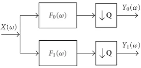
Figure 3. The FFB consists of two filtersF0(ω) and F1(ω) with complementary fan-shaped frequency bands followed by quincunx downsampling matricesQ. The ideal support of the fan filters correspond to the regions shown inFigure 1(a). A typical value forQis
Q=
⎡ ⎣1 −1
1 1
⎤
⎦ (1)
with downsampling ratio|detQ| = 2. Hence, the FFB is a maximally decimated structure where each subband is half the size of the input image. In the spatial domain, quincunx downsampling of an image sampled over a rectangular lattice results in subbands where one of the quincunx sublattices is discarded while the other lattice is remapped to a rectangular lattice through a±45◦rotation. The spatial support of the resulting subbands is diamond shaped. In the frequency domain, quincunx decimation has the effect of stretching and rotating the fan-shaped spectral support of the subbands such that frequency information is mapped into the [−π,π)2 frequency cell.
As a result of using a tree structure, the output of the first and second stages in Figure 2corresponds to the two-and four-channel BDFBs which split the frequency plane as shown in Figures 1(a)and 1(b), respectively. The third stage of the BDFB includes additional resampling matrices UiandBi. These matrices are unimodular, implying that they affect the ordering of the subband coefficients but not the number of coefficients [44]. Unimodular resampling induces skewing and stretching in the spatial and frequency domains. In this case, matricesUiresample the four subbands from the
Stage 1 Stage 2 Stage 3
Fan filter bank
Fan filter bank
Fan filter bank
Fan filter bank
Fan filter bank
Fan filter bank
Fan filter bank
U1
U2
U3
U4
B1
B2
B3
B4
B5
B6
B7
B8
Figure 2: Implementation of an eight bands BDFB using a tree structure with FFBs and backsampling matrices.
F0(ω) Q
F1(ω) Q
X(ω)
Y0(ω)
Y1(ω)
Figure 3: Maximally-decimated 2D two-channel fan filter bank structure using quincunx downsampling.
second stage such that the frequency support is remapped to a fan-shaped region. This operation allows the use of the FFB across all tree stages of the BDFB. The function of the Bimatrices is to adjust the sampling lattice at the output of the tree to attain subbands with rectangular geometry. The values of the unimodular matrices are determined using a set of rules derived by Park et al. [45]. It is easy to see from Figures 2 and3 that for an eight-band BDFB, the overall downsampling matricesDare given by
D=QQUiQBi, (2)
where=1, 2,. . ., 8 andi= /2. With the proper selection of Ui andBi, each D should be diagonal with one of the following forms:
C1= ⎡ ⎣2 0
0 4 ⎤
⎦, C2= ⎡ ⎣4 0
0 2 ⎤
⎦, (3)
be implemented by replicating the third stage of the tree structure inFigure 2[45].
2.2. Implementation of the BDFB Using Ladder Structures.
Given the tree structure of the BDFB, the design of the filter bank devolves to the design of the FFB. In practice, the FFB filters are designed to give a good approximation of the ideal passband specifications while meeting aliasing cancelation (AC), perfect reconstruction (PR), phase and smoothness constraints. Designing 2D filter banks with fan and diamond shaped passbands has been studied extensively [46–48]. For the BDFB, Bamberger proposed design methods using the 1D to 2D mapping introduced by Ansari [49], which transforms a 1D prototype into a 2D filter. This method led to a BDFB based on 1D quadrature mirror filters (filters satisfying H1(z) = H0(−z)), which has a very efficient 2D separable implementation structure in the polyphase domain. The resulting 2D FIR filters only provide AC and not PR. To achieve PR one could employ the 2D IIR filters introduced in [50], but often one prefers the simplicity of FIR filters.
Perfect reconstruction is a desirable property for any filter bank when the signal needs to be reconstructed. Versions of the BDFB with FIR PR filters were initially reported by Rosiles and Smith [39,42] based on the ladder filter banks proposed in [47, 48]. Ladder networks also offer a simple and flexible scheme to control the frequency domain filter specification. We should note that in the wavelet literature, ladder filters have been referred to as
lifting filters [51]. In this paper we use the ladder structure proposed in [48] to design 2D two-channel diamond filter banks consisting of filters H0(ω0,ω1) and H1(ω0,ω1) with complementary diamond passband/stopband regions. The FFB filters are obtained by shifting the diamond filters along the horizontal frequency axis by π, namely, F0(ω0,ω1) =
H0(ω0−π,ω1) andF1(ω0,ω1)=H1(ω0−π,ω1).
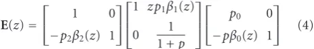
The simplest way to visualize the FFB implementation is to inspect the 2D two-channel ladder structure shown in Figure 5. There are three ladder steps where the filter-ing operations βi(z0)βi(z1) are performed. We note that these operations represent a separable filter in the spatial domain allowing for a low complexity implementation. The FFB is obtained by transforming a 1D ladder polyphase matrix [48]
E(z)=
⎡
⎣ 1 0
−p2β2(z) 1 ⎤ ⎦ ⎡ ⎢ ⎣
1 z p1β1(z)
0 1
1 +p
⎤ ⎥ ⎦ ⎡
⎣ p0 0
−pβ0(z) 1 ⎤ ⎦ (4)
to a 2D filter bank in two steps. First a 1D to 2D change of variables is applied to the entries ofE(z). The mapping consists of replacing the 1D transfer function β(z) with the separable 2D transfer function β(z0)β(z1) and the 1D delays z−1 with the 2D delays z−1
0 z−11. The resulting 2D filters H0(z0,z1) and H1(z0,z1) have diamond shaped passband support. The second step transformsH0(z0,z1) and
H1(z0,z1) to fan-shaped filters F0(z0,z1) and F1(z0,z1) by lettingz0 → −z0, which corresponds to a shift byπalong
theω0 axis. The constantsp0,p1,p2in the ladder structure are used to control the frequency response of the filters. In this case their values are p=1/2,p0 =p1=(1 +p)/2, and
p2=(1−p)/(1 +p).
Hence, we are left with the design of the 1D functions
βi(z). The following condition [47,48] for theβi(z) functions should be satisfied:
βi
ej2ω =
⎧ ⎪ ⎪ ⎨ ⎪ ⎪ ⎩
ej(−2N+1)ω, for 0≤ω≤π 2,
−ej(−2N+1)ω, for π
2 < ω≤π,
(5)
which impliesβi(ejω) has allpass behavior. An FIR solution that approximates (5) can be obtained by designing an even length, linear phase function with a magnitude response optimized to approximate unity. This is a very simple requirement that can be satisfied with widely available filter design algorithms, such as the Parks-McClellan filter design method. Moreover, we can choose to use the same ladder stage filter by making β(z) = β1(z) = β2(z) = β3(z), further simplifying the design procedure. As an example, filtersβ(z) of lengthL = 8 were designed using the Parks-McClellan algorithm. The 2D fan filter responses|F0(z0,z1)| and |F1(z0,z1)| obtained with the 1D to 2D mapping are presented inFigure 6using the sameβ(z) for all ladder stages. Finally, it is possible to design an FFB usingmaximally flat
1D ladder filters obtained with the closed-form Lagrange formula discussed in [47]. Using a maximally flat design has connections with wavelet theory and improves the smoothness of reconstructed images. An example of a test image processed with the BDFB is presented inFigure 4. The separation of directional information across channels can be verified visually.
2.3. The Undecimated Directional Filter Bank. The BDFB tree structure fromFigure 2 can be modified to obtain an undecimated directional filter bank (UDFB). The UDFB pro-ducesNbands with the same dimension as the input image, introducing significant redundancy. However, it provides shift invariance and well localized edge and texture detail;
Figure 7shows the output of an eight bands UDFB for the test image inFigure 4. Visually the undecimated subbands show very good separation of directional information.
Here we provide a brief overview of the UDFB, noting that a detailed derivation can be found in [42,52]. The UDFB has a similar tree structure as the BDFB (Figure 2). In the UDFB, the FFB blocks are replaced by two undecimated filter banks. In stage one we use an undecimated fan filter bank (UFFB). In stages two and three the FFB is replaced with an undecimated checkerboard filter bank (UCFB). As its name implies, the UCFB is formed by two complementary filters whose passbands resemble 2 × 2 checkerboard tiles. The UFFB and UCFB are related by a simple change of variables as described in [49]. In this case, the unimodular matricesUi andBisatisfy the relationshipBi=U−i1.
(a) Test image (b) Maximally-decimated subbands
Figure4: Example of an eight bands BDFB using a test image with localized directional structure.
Q
Q
β0(−z0)β0(z1)
β1(−z0)β1(z1)
β2(−z0)β2(z1)
−z0z1
z−1 0
p
p0 p 1
p2
1/(1 +p)
+ − + −
+ +
Figure5: Ladder structure for the implementation of a 2D two-channel biorthogonal analysis filter bank.
samples. The filtering operations are performed in this intermediate lattice geometry using the upsampled ladder filtersβi(z02)βi(z21). The rightmost downsampling operations return the subbands to the same sampling geometry as the input. Hence, the filtering operations remain separable in the undecimated structure and retain the computationally efficient implementation of BDFB. Given the relationship between the UFFB and UCFB, a ladder-based implemen-tation for the UCFB is easily obtained by removing the upsampling and downsampling matricesQfrom the UFFB structure inFigure 8.
2.4. Bamberger Pyramids. Other image decompositions like the 2D DWT, the complex-valued wavelet transform [53], and 2D Gabor representations [8, 9], separate informa-tion across different resolutions and orientations. The multiresolution analysis (MRA) is embedded in the filter bank structure. Alternatively, a multiresolution directional decomposition can be constructed using a polar-separable approach. In this case, each channel is generated by cascading a radial filter with a directional filter (or vice versa). Polar-separable spatial filters were proposed by Faugeras [4] in his seminal work on multichannel texture analysis. The steerable pyramid [54] is an example of a polar-separable decomposi-tion where the radial decomposidecomposi-tion is built by recursively applying a circular lowpass filter that produces a pyramid
of ring-shaped channels; each radial component is then processed with a steerable basis of directional derivatives. Similar polar-separable decompositions have been proposed in [55,56].
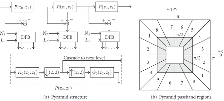
Given that many problems of interest in image processing and analysis use MRA as part of its processing, extending the theory of the BDFB to polar-separable representations is desirable. As it turns out polar-separable versions of the BDFB and UDFB can be easily constructed. For instance, we can form a polar-separable pyramid by combining aJ -level Laplacian pyramid with the BDFB [52,56]. The analysis structure is presented in Figure 9. At the high- and mid-frequency levels the subbands can be processed with the BDFB. If required, the UDFB can be used in place of the BDFB. More generally the directional decomposition can be designed independently at each resolution. For instance, the number of subbands and the order of the βi(z) filters can be chosen independently at each resolution. Since the polar components of the pyramids are invertible, it is easy to see that the overall system has PR. The frequency plane partitioning obtained with the Laplacian-Bamberger pyramid is shown inFigure 9.
There are many possible variations of pyramids based on the BDFB and UDFB. Next, we introduce several Laplacian-Bamberger pyramid configurations, each with a different level of redundancy. For the Laplacian pyramid we can also consider the case where shift invariance is needed at all resolutions and orientations. In this case we can remove all downsampling operations from the Laplacian structure and modify the lowpass kernels at each resolution level to
H0(z2
j
0,z2
j
1) andG0(z2
j
0,z2
j
0 0.2 0.4 0.6 0.8 1 1.2
60 50
40 30
20 10
0 0 10 20
30 40 50 60
(a)|F0(ω0,ω1)|
0 0.2 0.4 0.6 0.8 1 1.2
60 50
40 30
20 10
0 0 10 20
30 40 50 60
(b)|F1(ω0,ω1)|
Figure6: Magnitude response of the analysis fan filters obtained with a three-stage ladder structure.
Figure7: Subbands obtained from an eight bands UDFB.
to avoid downsampling altogether we can consider the fully undecimated pyramid (ULap-UDFB), which has a redundancy factor ofN(P−1) +1 (the low frequency channel is not directionally divided).
3. Framework for Multichannel Texture
Segmentation
Multichannel texture segmentation schemes can be des-cribed with the block diagram shown inFigure 10. For an
I × J input image X(i,j) composed of a mixture of C
texture classes, the output consists of a segmentation map
S(i,j) where a label from the set C = {1, 2,. . .,C} is assigned to each location (i,j). The underlying principle of the multichannel approach is based on the characterization of textures by their energy distribution over the spatial-frequency plane. To capture this energy distribution across different scales and orientations, multichannel transforms like Gabor filters, wavelet decompositions, local linear transforms, and Bamberger pyramids are used at the front end ofFigure 10. Each channel captures specific structural and statistical trends for a given texture. For instance, textures with strong directional components will contain more energy in the channels with frequency selectivity tuned to these components. These energy signatures can be used to differentiate among different texture classes. In our case, we employ Bamberger pyramids as the multichannel decomposition inFigure 10.
The remaining segmentation system components are discussed next. We closely follow the work by Randen and Husøy [57] in order to take advantage of the extensive comparative study they reported on texture segmentation. This paper is commendable in terms of providing seg-mentation benchmarks that can be used for convenient comparison. As a side note, we recently became aware of a similar benchmarking effort reported in [58]. To perform meaningful comparisons, it is important to compare the best algorithm implementations available and to use common databases. Fortunately, the segmentation schemes reported in [20,21,59,60] have used the same set of comparisons. Moreover, Randen and Husøy have made source code and their data set available over the internet [61] to enable results to be reproduced and compared.
Q
Q
Q
Q β0(−z20)β0(z21)
β1(−z20)β1(z21)
β2(−z20)β2(z21)
−z2 0z21
z−01
p
p0 p1
p2
1/(1 +p)
+ − + −
+ +
Figure8: Ladder structure implementation of the UFFB.
P(z0,z1) P(z0,z1) P(z0,z1)
DFB DFB DFB
+ − + − + −
· · · · · · · · ·
Cascade to next level N1
L1
N2
L2
N3
L3
H0(z0,z1) (2, 2) (2, 2) G0(z0,z1)
P(z0,z1)
+ + +
(a) Pyramid structure
3
4 5
6 8
1 2 3 4 5 6
7 7
8
1
2
ω1
π
π/2
π/2 π ω0
(b) Pyramid passband regions
Figure 9: (a) Bamberger pyramid using the Laplacian pyramid structure combined with the BDFB. (b) Frequency plane partitioning achieved by Bamberger pyramids.
second nonlinearity consists of a normalization operation that limits the dynamic range of the energy maps and removes spurious energy values. The resulting mapsεk(i,j) provide a feature set for each pixel location (i,j). This feature set is used as input to a pattern classifier.
The nonlinearities are reminiscent of the inhibitory operations of neurons. They are necessary as a vehicle to combine or inhibit responses of neighboring neurons (i.e., subband coefficients) [6]. Unser and Eden [62] did an extensive study on the types and effectiveness of the non-linear operations. In this paper, we use both the rectifying and normalizing nonlinearities f1(x) = |x|2 and f2(x) = log(x), respectively, which were concluded to give the best segmentation performance in [62].
Ideally, we would like to extract primitives and primitive placement rules that characterize a texture. However, this is a rather difficult analysis task that remains an open problem. Instead we measure the local interactions of channel coeffi -cients around each location (i,j) to infer the structure of a texture. These interactions have been commonly measured using local energy estimates. For each channel, an energy mapek(i,j) is obtained by performing a spatial smoothing on the rectified channelαk(i,j). This operation is given by the convolution
ek
i,j=gk
i,j∗f1
sk
i,j, (6)
where gk(i,j) is a 2D kernel and k identifies the channel under analysis. Intuitively, averaging over a region with similar statistical primitives will produce slowly varying
responses indicating the presence of patches with uniform energy.
The responses of the filters gk(i,j) should be carefully selected. First, we want the filter dimensions to be as large as possible to obtain good energy estimates. Second, we want filters with small regions of spatial support in order to promote good detection of texture boundaries. Gaussian kernels have been shown to be a good compromise among this set of conflicting requirements. The 2D filters are implemented as finite separable filters using the basic 1D Gaussian response
g(n)=√1
2πσs exp
−1
2
n2
σ2 s
(7)
with spatial support given by 2σs. The parameterσsdepends on the average channel frequencyu0(i.e., the centroid) for a given channel [9] and is given by
σs= 1
2√2u0. (8)
In the case of Bamberger pyramids, the directional sub-bands have truncated wedge-shaped passsub-bands as shown in
Figure 9(b). The center frequency is given byu0=
Filter bank Nonlinearity Local energy estimation
Normalizing
nonlinearity Classifier
. . .
. . .
. . .
. . . X(i,j)
sk(i,j) αk(i,j) ek(i,j) εk(i,j)
S(i,j)
Figure10: Classical segmentation system based on multichannel filtering.
Collage (a) Collage (f)
Collage (h) Collage (j)
Figure11: Subset of the texture collages mixtures used in this paper. The complete set is presented in [57].
kernels which do not introduce sufficient smoothing in the channels. In order to generate larger windows, we found that
σs=
σs,02 +σs,12, (9)
where
σs,0= 1
2√2f0, σs,1=
1
2√2f1 (10)
provides excellent results as we will discuss later in the paper.
3.2. Classification Stage. After feature extraction, feature vectors are formed from the εk(i,j). For a filter bank with K channels, each image pixel X(i,j) is described with aK-dimensional feature vectorfi,j = [ε1(i,j) ε2(i,j) · · · εK(i,j)]T.Following [57], we adopt the Learning Vector Quantization (LVQ) algorithm from Kohonen [63] as the classifier inFigure 10. LVQ is a supervised classification algo-rithms. It seems that the main reason for the initial selection of LVQ was the availability of an open source implementation [64]. More specifically theolvq1program was used, which automatically selects some classifier parameters based on the data.
The classification procedure is straightforward. Labeled feature vectors produced from training samples are then used to train the LVQ classifier, producing a set of Nc labeled
prototypes M = {(m1,v1), (m2,v2),. . ., (mNc,vNc)}. Each texture classc is assigned a number of prototypes directly proportional to the number of labeled vectors used for training. At the classification stage, a feature vector fi,j is assigned to the classvicorresponding to the nearest distance prototypemifromM.
3.3. Description of Test Image Data. We use the image collages were introduced as part of the framework developed in [57]. A subset of the texture collages is shown inFigure 11. The data set consists of 12 texture collages, each exhibiting dif-ferent degrees of difficulty in terms of the number of textures and region shapes. The data set contains five 256×256 images with five textures, two 512×512 images with 16 textures, two 256×640 images with 10 textures, and three 256×512 images with only two textures. The histograms were equalized in each image in order to eliminate discrimination based on first-order statistics. To generate codebooks for the LVQ classifier, a 256×256 training sample is available for each texture class. The training samples are not part of the test image set.
Table1: Segmentation errors for ULap-UDFB pyramids withP=4 radial decomposition levels. PM denotes Parks-McClellan. MF denotes for maximally flat.
Pyramid Segmentation errors for texture collages
Parameters L (a) (b) (c) (d) (e) (f) (g) (h) (i) (j) (k) (l) Mean
N=4, three-step ladder, PM design
4 7.02 32.00 20.19 26.77 15.24 54.93 61.31 30.68 66.67 2.94 3.00 7.18 27.33
12 5.55 30.09 19.11 26.90 16.31 52.91 59.35 28.30 68.36 2.69 3.09 6.83 26.62
18 5.33 31.16 19.33 28.05 16.75 45.18 67.65 28.63 48.25 3.02 3.08 6.82 25.27
N=8, two-step ladder, PM design
4 5.46 24.96 18.23 18.45 14.19 35.12 48.02 26.86 30.13 0.90 1.95 4.28 19.04
12 5.35 22.03 16.87 18.47 13.68 32.84 45.49 22.57 49.01 1.34 2.08 4.21 19.49
18 5.35 24.19 16.09 18.44 13.16 31.03 45.26 24.01 50.86 1.76 1.54 4.21 19.66
N=8, three-step ladder, MF design
4 6.13 20.40 15.12 19.97 12.66 41.35 47.60 26.54 54.33 0.86 2.52 4.82 21.02
12 4.74 18.50 12.84 20.36 12.48 35.38 44.68 22.51 44.18 0.67 1.50 4.68 18.55
18 4.66 19.33 12.97 16.66 12.20 33.53 41.95 22.28 29.49 0.64 1.39 4.40 16.63
N=8, three-step ladder,PM design
4 5.43 18.27 12.28 19.82 12.99 32.41 41.22 22.87 42.98 0.75 1.87 4.52 17.95
12 4.67 19.48 12.37 17.01 14.18 31.12 48.02 20.60 37.88 0.58 1.57 4.82 17.69
18 4.64 20.04 12.34 17.70 13.45 30.72 44.4672 20.91 29.10 0.60 1.36 4.93 16.69
over a range of codebook sizes using representative samples of the data set. Segmentation errors seemed to plateau for codebook sizes between 100 and 200 for all texture collages. The codebook size of 160 was chosen since it is a common multiple of the the number of different texture classes in the collages. Using this value allows an even distribution of LVQ codebook prototypes for all textures.
4. Texture Segmentation Using an Undecimated
Bamberger Pyramid
Our aim here is to use Bamberger pyramids as the front end to a multichannel texture segmentation system. In
Section 2.4, we introduced different configurations of the Bamberger pyramid. Shift invariant undecimated transforms have typically shown better performance than subsampled systems [57]. Based on this observation, we chose the ULap-UDFB pyramid where the pyramid and directional components are undecimated.
The multichannel segmentation framework discussed in the previous section was implemented using the ULap-UDFB. We chose the number of pyramid levelsP, number of directional bands N, number of ladder stages in the UFFB and UCFB, and the length L of the 1D prototype
β(z) carefully to maximize performance. Determining these parameters was done experimentally through an extensive evaluation of segmentations over the feature space. For our experiments, we first determined that four pyramid levels (P =4) gave the best performance. We present results with
N= {4, 8}using two-stage and thee-stage ladder structures. Additionally, we present results usingβ(z) filters of length
L= {4, 12, 18}designed with the Parks-McClellan algorithm and the maximally flat filter design algorithm. For values higher thanL=18 no improvements were observed.
The feature vector dimension is given by K = (P −
1)Nwhere the lower frequency channel of the ULap-UDFB pyramids has been excluded from the classification stage. Finally, the LVQ codebook size was set to 160 as described before. Segmentation errors for each collage and the average segmentation error are presented in Table 1 for different parameter combinations. We define the segmentation error as the percentage of pixels that were incorrectly classified with respect to the total number of pixels in the image. We also show the classification maps and the error maps for some of the test collages inFigure 12.
At the rightmost column of the table we compute the average segmentation error for each system. Based on these averages we arrive at the following conclusions.
(1) Very similar performance is obtained for two-stage and three-stage ladder structures. We choose the three-stage ladder structures for subsequent work as they provide better passband quality.
(2) We observed that eight-band UDFB systems signifi-cantly outperform four-band UDFB systems.
(3) Systems based on the Parks-McClellan design per-form somewhat better than the maximally flat sys-tems. The average of the segmentation errors for each value ofLshows that Parks-McClellan systems have more consistent behavior asLis varied, while maximally flat designs show more sensitivity to this parameter. Moreover, in some cases large L works marginally better than smallerL.
Segmentation map and error map for collage (a)
ULap-UDFB segmentation ULap-UDFB error ULap-BDFB error
Segmentation map and error map for collage (f)
Segmentation map and error map for collage (h)
ULap-UDFB segmentation ULap-UDFB error ULap-BDFB error
Segmentation map and error map for collage (j)
ULap-UDFB segmentation ULap-UDFB error ULap-BDFB error
Figure12: ULap-UDFB and ULap-BDFB segmentation maps and errors from Tables1and 2withL = 12,J = 4, andN = 8 using Parks-McClellan filter design.
Because of the more consistent performance as a function of
L, we favor the use of ladder-based UDFBs whose step filters are designed using the Parks-McClellan algorithm.
5. Texture Segmentation Based on
Decimated Bamberger Pyramids
The ULAP-UDFB segmentation systems from the previous sections require a 24-fold data expansion in the training and classification stages. Hence, any possibility to reduce the computational and storage requirements is highly desirable.
The decision to use a fully undecimated Bamberger pyramid was based on previous findings where full rate systems work significantly better than systems using subsampled channels [57]. However, we also investigated Bamberger pyramids using the (maximally decimated) BDFB. To assess the complexity-performance tradeoffs between the BDFB and the UDFB.
not use the lowpass pyramid level in our feature extraction process. Hence, using the ULap-BDFB with P = 4 and
N = 8 has an eight-fold reduction in storage compared to the ULap-UDFB. Moreover, the complexity reduction in the feature extraction, training, and classification stages is also significant.
The segmentation system fromFigure 10requires some significant changes. The nonlinear operations remain the same, while the energy map generation needs to be modified to account for the spatial characteristics of the subbands. As we recall from Section 2, the output of the BDFB is maximally decimated. In the case of a four-band BDFB, the subbands are equally halved on both directions. In this case, each location (i,j) on a subband corresponds to the neighborhood{(2i, 2j), (2i+1, 2j), (2i, 2j+1), (2i+1, 2j+1)} at the input image and generating a subsampled energy map is straightforward.
On the other hand, an eight-band BDFB poses a slightly more difficult task to obtain feature mapsεk(i,j). We recall fromFigure 4that the eight-band BDFB produces subbands with nonuniform sizes whose overall downsampling matri-ces are given in (3). For instance, a 512×512 input image produces four 256 × 128 subbands and four 128 × 256 subbands. Hence we need a way to produce the energy maps
ek(i,j) from decimated subbandssk(i,j) and feature maps
εk(i,j) of equal size. To obtain energy mapsek(i,j) we need to consider the effect ofC1andC2on the original data. For a diagonal downsampling matrix
D=
d0 0 0 d1
, (11)
decimation translates to stretching the frequency axes by factors ofd0andd1alongω0andω1, respectively. Given the periodic nature of the 2D subband frequency responses, the centroid frequencies along each dimension are mapped to
fd0 =(d0f0) modπ and fd1 = (d1f1) modπ.Using these values, we can computeσs,0andσs,1as before to findσsusing (9).
To solve the nonuniform subband size issue, the simplest solution is to produce energy maps with uniform size by averaging spatial locations along the larger of the two dimension. For a feature mapεk(i,j) with a spatial geometry produced by C1 we form a new set of “averaged” energy maps given by
ak
i,j= εk
2i,j+εk
2i+ 1,j
2 (12)
for all j andi = 0, 1,. . ., (I/2)−1. Similarly, for subbands whose downsampling matrix isC2we obtain
ak
i,j= εk
i, 2j+εk
i, 2j+ 1
2 (13)
for all i and j = 0, 1,. . ., (J/2)−1. The resulting energy mapsak(i,j) have equal dimensions (I/4)×(J/4). Averaging the channels reduces spatial resolution. On the other hand classifier complexity is reduced by an additional factor of 2. The feature vector for subband spatial location (i,j) is
now given byfi,j=[a1(i,j)a2(i,j) · · · aK(i,j)]TwithK= (P−1)N. The LVQ classifier produces segmentation maps
S(i,j) of size I/(2M−1)×J/(2M−1), where M = 3 for the eight-band BDFB. We recallMis the number of stages in the BDFB tree structure. Each segmentation map location (i,j) spatially colocates with an (M−1)×(M−1) region on the original texture. To produce a full rate segmentation map, we perform a simple interpolation ofS(i,j) by computing a Kronecker product with an M×M structuring element of ones, followed by a 3×3 median filter to reduce jagged edges around the texture boundaries.
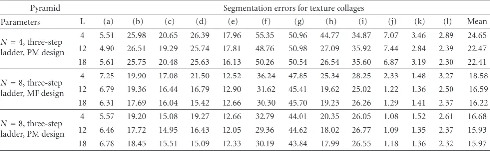
With these modifications to the segmentation scheme, we present the same evaluation of the design parameter space as in the previous section. The segmentation results are presented in Table 2. First we note that, as before, the
N = 8 systems outperform N = 4. This is remarkable since forN = 4 there is four times the amount of spatial information than with N = 8, and it could be expected that the N = 4 case would provide better segmentations. This experimental evidence seems to imply that for texture segmentation, directional selectivity is a more important property than spatial resolution. This is further discussed in the next section where we compare our results with other maximally decimated decompositions.
Table2: Segmentation errors for ULap-BDFB pyramids withP=4 radial decomposition levels. PM denotes Parks-McClellan. MF denotes maximally flat.
Pyramid Segmentation errors for texture collages
Parameters L (a) (b) (c) (d) (e) (f) (g) (h) (i) (j) (k) (l) Mean
N=4, three-step ladder, PM design
4 5.51 25.98 20.65 26.39 17.96 55.35 50.96 44.77 34.87 7.07 3.46 2.89 24.65 12 4.90 26.51 19.29 25.74 17.81 48.76 50.98 27.09 35.92 7.44 2.84 2.39 22.47 18 5.61 25.75 20.48 25.63 16.13 50.26 50.54 26.54 35.60 6.87 3.19 2.30 22.41
N=8, three-step ladder, MF design
4 7.25 19.90 17.08 21.50 12.52 36.24 47.85 25.34 28.25 2.33 1.48 3.27 18.58 12 6.79 19.36 16.44 16.79 12.90 31.62 45.41 19.62 25.02 1.22 1.36 2.50 16.59 18 6.31 17.69 16.04 15.42 12.66 30.30 45.70 19.23 26.26 1.29 1.41 2.37 16.22
N=8, three-step ladder, PM design
4 5.57 19.20 15.08 19.27 12.66 32.79 44.01 20.35 26.05 1.08 1.52 2.61 16.68 12 6.46 17.72 14.95 16.43 12.05 29.36 44.62 18.02 26.77 1.09 1.35 2.37 15.93 18 6.78 18.45 15.51 15.09 12.33 30.19 43.84 17.99 26.55 1.18 1.36 2.32 15.97
explained by the class resolution versus spatial resolution tradeoffdescribed by Wilson and Spann [10]. As the spatial resolution is reduced by the downsampling operations, the class resolution of the textures in the image is increased. A similar finding was reported by Jain and Farrokhnia in [9] with their interpretation on the use of local energy maps as blob detectors.
6. Comparison with Other Multichannel
Schemes
In this section we compare the segmentation results pre-sented in this paper with other multichannel segmentation schemes. An extensive number of filter banks were evaluated in [57]. The mean classification error over the texture collages is presented inTable 3.
In the decimated multichannel systems reported in [57], the energy maps of the lower rate subbands were upsampled to full rate in order to deal with nonuniform sized channels. The upsampling process could be as simple as sample replication or as complex as using anti-imaging filters. From the average results shown in the tables, it appears that upsampling the subbands hinders the discriminative abilities of the feature set, probably as a result of the imaging introduced by this operation.
Table 3 also includes the DT-CWT result reported by de Rivaz [20]. The DT-CWT decomposition gives a clear improvement compared to the rest of the filter banks. The DT-CWT is nearly shift invariant and has twice the directional selectivity of the classical DWT. De Rivaz con-cluded that the improved directionality of the DT-CWT is the principal mechanism behind the improvement in segmentation quality and that the complex-valued nature of this representation is not relevant. In fact, it is shown in [20] that the real part of the DT-CWT performed as well as the full DT-CWT. This result supports our own conclusions about DFB-based systems that increased directional selectivity improves the discriminative power of the local-energy features despite the loss in spatial resolution caused by downsampling.
For further comparisons we considered the local DCT, the full rate nonuniform QMF filter bank with 40 sub-bands, and the DT-CWT. Additionally, we implemented a segmentation system using the Steerable Pyramid (SPyr) from Simoncelli et al. [54]. For the SPyr we use four pyramid levels combined with an eight-band angular component. The lower resolution energy maps were upsampled using a combination of zero-order interpolation followed by a 3×3 median filter. We selected the ULap-BDFB and ULap-UDFB systems that provide the lowest average segmentation error for comparison. We present the classification errors for all the texture collages inTable 4.
Using the average segmentation errors as a single metric for performance, we see that the our systems are the top performers. However, the average classification error over simplifies the picture. It might be more useful to look at the collages on a case-by-case basis. From this point of view, we see that except for collages (g), (j), and (k), our systems provide the best results. The DT-CWT performs marginally better on collages (g), (j), and (k). It should be noted that the differences in classification error are marginal among the top performers and that their segmentation maps will not have visually discernable differences. The SPyr is the worst performer. Similar to other systems with decimated channels, upsampling the lower rate energy maps to full rate does not improve segmentation.
Complexity is another dimension for comparison. With respect to complexity, the DT-CWT (4-levels, 6-orientations) is comparable to the Lap-DFB system (3-levels, 8-directions). The DT-CWT is redundant by a factor of four, while the ULap-BDFB increases the data rate by factor of three. Additionally, the computation of features from the DT-CWT is more involved, since the local energy calculation has to be computed from complex-valued subbands. Hence, considering the whole picture, the ULap-BDFB is arguably a better choice than the DT-CWT from both complexity and performance perspectives.
Table3: Average classification errors for different segmentation systems.
Segmentation Method Mean classif. error Segmentation method Mean classif. error
Laws Filters 28.32 Cooccurrence 29.1
Ring/wedge filters 30.6 Autoregressive 26.32
Dyadic Gabor 27.77 Eigenfilter 26.17
Gabor filt. bank 31.45 Prediction error 29.27
DCT (3×3) 24.85 Optimized FIRJu 26.36
Daub. 4 (UDWT) 22.55 Back Prop. NN 51.92
Daub. 4 (DWT) 28.55 DT-CWT [20] 18.0
QMF 16-tap (40 subbands) 20.83
Table4: Comparison of segmentation results for different multichannel approaches.
Description (a) (b) (c) (d) (e) (f) (g) (h) (i) (j) (k) (l) Mean
DCT 13.2 27 25.5 37.8 22.6 40.9 49 38.2 33 6.4 2.2 2.5 24.85 FR-QMF 8.7 18.9 23.3 18.4 17.2 36.4 41.7 39.8 28.5 8.1 0.8 8.2 20.83 SPyr 7.1 26.2 24.3 29.9 20.2 42.27 63.92 35.29 43.31 2.99 1.91 12.98 25.87 DT-CWT 10.9 21.8 16.2 16.6 17.3 33.8 40.4 19.3 28.6 0.6 1.1 9.3 17.99 ULap-UDFB,L=18 4.66 19.33 12.97 16.66 12.20 33.53 41.95 22.28 29.49 0.64 1.39 4.40 16.63 ULap-DFBL=12 6.46 17.72 14.95 16.43 12.05 29.36 44.62 18.02 26.77 1.09 1.35 2.37 15.93
selectivity compared to the traditional 2D DWT. The perfor-mance of Gabor filter banks, which can have an arbitrary number of orientations, is relatively poor in general. This may be attributed to the poor stopband rejection inherent with Gaussian filters.
As a final note we point our that the motivation to use full rate decompositions with this level of redundancy is to exploit shift invariance (SI). However, our results suggest that the improved directional selectivity of the BDFB and UDFB is a more dominant property than SI. This is supported experimentally by comparing the BDFB an the ULap-UDFB results. Hence, we can de-emphasize the requirement for SI and in so doing, achieve a substantial reduction in computation and storage.
7. Conclusions
In this paper we presented the use of Bamberger pyramids for multichannel texture segmentation. These polar-separable pyramids are composed of flexible filter bank structures that allow fine tuning of several design parameters including a tight control of filter specifications, the number of directional bands at each scale, and the redundancy factor of the decom-position. A well-known supervised segmentation framework using LVQ as a classifier was adopted in order to allow a detailed comparison with other multichannel transforms.
A common belief in multichannel texture segmentation is that SI and highly redundant decompositions tend to outperform maximally decimated representations. Here we report a contradictory result to this perspective. We showed that the ULap-BDFB pyramid with decimated directional channels performs at the same level (and in some cases better) as the full-rate ULap-UDFB. We infer that the angular frequency selectivity provided by Bamberger pyramids is the most significant factor in improving segmentation. In other
words, the BDFB and UDFB provide an excellent packing of texture energy across subbands.
A comparison with other multichannel schemes shows that the ULap-BDFB and ULap-UDFB pyramids provide the best overall performance. After considering complexity and storage requirements, the ULap-BDFB pyramid is particularly attractive for segmentation compared to the other multichannel representations discussed in this paper. Although the results are based on the texture collages tested, we speculate that the results will be similar for other collages given the wide gamut of variations presented in the test images.
The work here has focused on evaluating Bamberger pyramids as the front end of the multichannel segmentation system. We have not yet made an attempt to improve the feature extraction and classification steps. As seen in some of our results, there is still room for improvement. To this effect, we are currently exploring the use of classifier ensem-bles (e.g., boosting) to improve classification performance. Another line of work under study is texture segmentation using multiresolution Markov random fields (MRFs). Recent work on MRF segmentation using the DWT and the DT-CWT [22–24] indicate that directional information is a key factor on improving the estimation of the segmentation map. Finally, the exploration of algorithms based on physiology seems to have come to a halt. Current findings on the neural mechanisms of the visual cortex suggest revisiting this topic in the near future.
References
[1] B. Julesz, “Texton gradients: the texton theory revisited,”
Biological Cybernetics, vol. 54, no. 4-5, pp. 245–251, 1986. [2] F. W. Campbell and J. J. Kulikowski, “Orientational selectivity
no. 2, pp. 437–441, 1966.
[3] J. G. Daugman, “Uncertainty relation for resolution in space, spatial frequency, and orientation optimized by two-dimensional visual cortical filters,” Journal of the Optical Society of America A, vol. 2, no. 7, pp. 1160–1169, 1985. [4] O. D. Faugeras, “Texture analysis and classification using
a human visual model,” in Proceedings of the International Conference on Pattern Recognition (ICPR ’78), pp. 549–552, 1978.
[5] K. I. Laws, “Rapid texture identification,” inImage Processing for Missile Guidance, vol. 238 ofProceedings of SPIE, pp. 376– 380, 1980.
[6] J. Malik and P. Perona, “Preattentive texture discrimination with early vision mechanisms,”Journal of the Optical Society of America A, vol. 7, no. 5, pp. 923–932, 1990.
[7] J. M. Coggins and A. K. Jain, “A spatial filtering approach to texture analysis,”Pattern Recognition Letters, vol. 3, no. 3, pp. 195–203, 1985.
[8] A. C. Bovik, M. Clark, and W. S. Geisler, “Multichannel texture analysis using localized spatial filters,”IEEE Transactions on Pattern Analysis and Machine Intelligence, vol. 12, no. 1, pp. 55–73, 1990.
[9] A. K. Jain and F. Farrokhnia, “Unsupervised texture segmen-tation using Gabor filters,”Pattern Recognition, vol. 24, no. 12, pp. 1167–1186, 1991.
[10] R. Wilson and M. Spann, “Finite prolate spheroidal sequences and their applications II: image feature description and segmentation,” IEEE Transactions on Pattern Analysis and Machine Intelligence, vol. 10, no. 2, pp. 193–203, 1988. [11] A. K. Jain and K. Karu, “Learning texture discrimination
masks,”IEEE Transactions on Pattern Analysis and Machine Intelligence, vol. 18, no. 2, pp. 195–205, 1996.
[12] S. G. Mallat, “Multifrequency channel decompositions of images and wavelet models,”IEEE Transactions on Acoustics, Speech, and Signal Processing, vol. 37, no. 12, pp. 2091–2110, 1989.
[13] M. Unser, “Texture discrimination using wavelets,” in Proceed-ings of the IEEE Conference on Computer Vision and Pattern Recognition (CVPR ’93), pp. 640–641, 1993.
[14] R. Porter and N. Canagarajah, “A robust automatic clustering scheme for image segmentation using wavelets,”IEEE Trans-actions on Image Processing, vol. 5, no. 4, pp. 662–665, 1996. [15] S. Arivazhagan and L. Ganesan, “Texture segmentation using
wavelet transform,”Pattern Recognition Letters, vol. 24, no. 16, pp. 3197–3203, 2003.
[16] Y.-C. Lin, T. Chang, and C.-C. J. Kuo, “Hierarchical texture segmentation with wavelet packet transform and adaptive smoothing,” inVisual Communications and Image Processing (VCIP ’94), vol. 2308 ofProceedings of SPIE, pp. 1954–1965, Chicago, Ill, USA, September 1994.
[17] M. Unser, “Texture classification and segmentation using wavelet frames,”IEEE Transactions on Image Processing, vol. 4, no. 11, pp. 1549–1560, 1995.
[18] S. Liapis, N. Alvertos, and G. Tziritas, “Unsupervised texture segmentation using discrete wavelet frames,” inProceedings of the European Signal Processing Conference (EUSIPCO ’98), pp. 1341–1344, 1998.
[19] S. C. Kim and T. J. Kang, “Texture classification and segmenta-tion using wavelet packet frame and Gaussian mixture model,”
Pattern Recognition, vol. 40, no. 4, pp. 1207–1221, 2007. [20] P. de Rivaz,Complex wavelet based image analysis and synthesis,
Ph.D. thesis, University of Cambridge, Cambridge, UK, 2000. [21] P. R. Hill, C. N. Canagarajah, and D. R. Bull, “Image segmenta-tion using a texture gradient based watershed transform,”IEEE Transactions on Image Processing, vol. 12, no. 12, pp. 1618– 1633, 2003.
[22] B.-G. Kim, J. I. Shim, and D.-J. Park, “Fast image segmentation based on multi-resolution analysis and wavelets,” Pattern Recognition Letters, vol. 24, no. 16, pp. 2995–3006, 2003. [23] J. X. Sun, D. B. Gu, S. Zhang, and Y. Chen, “Hidden Markov
Bayesian texture segmentation using complex wavelet trans-form,”IEE Proceedings: Vision, Image and Signal Processing, vol. 151, no. 3, pp. 215–223, 2004.
[24] H. Noda, M. N. Shirazi, and E. Kawaguchi, “MRF-based texture segmentation using wavelet decomposed images,”
Pattern Recognition, vol. 35, no. 4, pp. 771–782, 2002. [25] R. H. Bamberger and M. J. T. Smith, “A filter bank for the
directional decomposition of images: theory and design,”IEEE Transactions on Signal Processing, vol. 40, no. 4, pp. 882–893, 1992.
[26] J. G. Rosiles and M. J. T. Smith, “Image denoising using direc-tional filter banks,” inProceeedings of the IEEE International Conference on Image Processing, vol. 3, pp. 292–295, Vancouver, Canada, September 2000.
[27] J. G. Rosiles, M. J. T. Smith, and R. M. Mersereau, “SAR image speckle removal using Bamberger pyramids,” inProceeedings of the IEEE International Conference on Image Processing (ICIP ’06), pp. 2345–2348, October 2006.
[28] S.-I. Park, M. J. T. Smith, and R. M. Mersereau, “Target recognition based on directional filter banks and higher-order neural networks,”Digital Signal Processing A, vol. 10, no. 4, pp. 297–308, 2000.
[29] T. Randolph,Image compression and classification using nonlin-ear filter banks, Ph.D. thesis, Georgia Institute of Technology, Atlanta, Ga, USA, 2001.
[30] S.-I. Park, M. J. T. Smith, and J. J. Lee, “Fingerprint enhance-ment based on the directional filter bank,” inProceedings of the IEEE International Conference on Image Processing (ICIP ’00), vol. 3, pp. 793–796, Vancouver, Canada, September 2000. [31] T. R. Randolph and M. J. T. Smith, “Fingerprint image
enhancement using a binary angular representation,” in
Proceedings of the IEEE International Conference on Acoustics, Speech and Signal Processing (ICASSP ’01), vol. 3, pp. 1561– 1564, May 2001.
[32] M. A. Khan, M. K. Khan, M. A. U. Khan, and S. Lee, “Endothelial cell image enhancement using decimation-free directional filter banks,” inProceedings of the IEEE Asia-Pacific Conference on Circuits and Systems (APCCAS ’06), pp. 884– 887, December 2006.
[33] F. A. Mujica, R. Murenzi, M. J. T. Smith, and S.-I. Park, “Motion estimation using the spatio-temporal continuous wavelet transform: new results and alternative implementa-tions,” inProceedings of the IEEE International Conference on Image Processing (ICIP ’00), vol. 2, pp. 550–553, September 2000.
[36] J. G. Rosiles and M. J. T. Smith, “Texture classification with biorthogonal directional filter bank,” in Proceedings of the IEEE International Conference on Acoustics, Speech and Signal Processing (ICASSP ’01), vol. 3, pp. 1549–1552, Salt Lake, Utah, USA, May 2001.
[37] K.-O. Cheng, N.-F. Law, and W.-C. Siu, “Multiscale directional filter bank with applications to structured and random texture retrieval,”Pattern Recognition, vol. 40, no. 4, pp. 1182–1194, 2007.
[38] J. G. Rosiles, M. J. T. Smith, and R. M. Mersereau, “Rotation invariant texture classification using bamberger pyramids,” in
Proceedings of the IEEE International Conference on Multimedia and Expo (ICME ’05), pp. 1010–1013, July 2005.
[39] J. G. Rosiles and M. J. T. Smith, “Texture segmentation using a biorthogonal directional decomposition,” inProceedings of the Systematics, Cybernetics and Informatics (SCI ’00), Orlando, Fla, USA, July 2000.
[40] P. S. Hong, L. M. Kaplan, and M. J. T. Smith, “Hyperspectral image segmentation using filter banks for texture augmen-tation,” inProceedings of the IEEE Workshop on Advances in Techniques for Analysis of Remotely Sensed Data, pp. 254–258, October 2003.
[41] P. S. Hong, L. M. Kaplan, and M. J. T. Smith, “A comparison of the octave-band directional filter bank and gabor filters for texture classification,” inProceedings of the International Conference on Image Processing (ICIP ’04), vol. 3, pp. 1541– 1544, October 2004.
[42] J. G. Rosiles and M. J. T. Smith, “A low complexity undeci-mated directional image decomposition,” inProceedings of the IEEE International Conference on Image Processing (ICIP ’03), vol. 1, pp. 1049–1052, 2003.
[43] R. H. Bamberger,The directional filterbank: a multirate filter bank for the directional decomposition of images, Ph.D. thesis, Georgia Institute of Technology, Atlanta, Ga, USA, 1990. [44] P. P. Vaidyanathan, Multirate Systems and Filter Banks,
Prentice-Hall, Englewood Cliffs, NJ, USA, 1993.
[45] S.-l. Park, M. J. T. Smith, and R. M. Mersereau, “A new directional filter bank for image analysis and classification,” in
Proceedings of the IEEE International Conference on Acoustics, Speech and Signal Processing (ICASSP ’99), vol. 3, pp. 1417– 1420, Phoenix, Ariz, USA, March 1999.
[46] E. Viscito and J. P. Allebach, “The analysis and design of multidimensional FIR perfect reconstruction filter banks for arbitrary sampling lattices,”IEEE Transactions on Circuits and Systems, vol. 38, no. 1, pp. 29–41, 1991.
[47] S.-M. Phoong, C. W. Kim, P. P. Vaidyanathan, and R. Ansari, “A new class of two-channel biorthogonal filter banks and wavelet bases,”IEEE Transactions on Signal Processing, vol. 43, no. 3, pp. 649–665, 1995.
[48] R. Ansari, C. W. Kim, and M. Dedovic, “Structure and design of two-channel filter banks derived from a triplet of halfband filters,”IEEE Transactions on Circuits and Systems II, vol. 46, no. 12, pp. 1487–1496, 1999.
[49] Ansari, “Efficient IIR and FIR fan filters,”IEEE Transactions on Circuits and Systems, vol. 34, no. 8, pp. 941–945, 1987. [50] M. J. T. Smith and S. L. Eddins, “Analysis/synthesis techniques
for subband image coding,” IEEE Transactions on Acoustics, Speech, and Signal Processing, vol. 38, no. 8, pp. 1446–1456, 1990.
[51] I. Daubechies and W. Sweldens, “Factoring wavelet transforms into lifting steps,”Journal of Fourier Analysis and Applications,
vol. 4, no. 3, pp. 245–267, 1998.
[52] J. G. Gonzalez Rosiles, Image and texture analysis using biorthogonal angular filter banks, Ph.D. thesis, Georgia Insti-tute of Technology, Atlanta, Ga, USA, 2004.
[53] N. G. Kingsbury, “The dual-tree complex wavelet transform: a new efficient tool for image restoration and enhancement,” in Proceedings of the European Signal Processing Conference (EUSIPCO ’98), vol. 1, pp. 319–322, Rhodes, Greece, Septem-ber 1998.
[54] E. P. Simoncelli, W. T. Freeman, E. H. Adelson, and D. J. Heeger, “Shiftable multiscale transforms,”IEEE Transactions Information Theory, vol. 38, no. 2, pp. 587–607, 1992. [55] H. Greenspan, S. Belongie, R. Goodman, P. Perona, S. Rakshit,
and C. H. Anderson, “Overcomplete steerable pyramid filters and rotation invariance,” inProceedings of the IEEE Computer Society Conference on Computer Vision and Pattern Recognition (CVPR ’94), pp. 222–228, 1994.
[56] M. N. Do and M. Vetterli, “Pyramidal directional filter banks and curvelets,” inProceedings of the IEEE International Conference on Image Processing (ICIP ’01), vol. 3, pp. 158–161, October 2001.
[57] T. Randen and J. H. Husøy, “Filtering for texture classification: a comparative study,”IEEE Transactions on Pattern Analysis and Machine Intelligence, vol. 21, no. 4, pp. 291–310, 1999. [58] M. Haindl and S. Mikes, “Texture segmentation benchmark,”
inProceedings of the 19th International Conference on Pattern Recognition (ICPR ’08), pp. 1–4, December 2008.
[59] N. Malpica, J. E. Ortu˜no, and A. Santos, “A multichannel watershed-based algorithm for supervised texture segmenta-tion,”Pattern Recognition Letters, vol. 24, no. 9-10, pp. 1545– 1554, 2003.
[60] S. Liapis, E. Sifakis, and G. Tziritas, “Colour and texture segmentation using wavelet frame analysis, deterministic relaxation, and fast marching algorithms,”Journal of Visual Communication and Image Representation, vol. 15, no. 1, pp. 1–26, 2004.
[61] T. H. Randen, “Texture segmentation framework,”http://www .ux.uis.no/∼tranden, 1999.
[62] M. Unser and M. Eden, “Nonlinear operators for improving texture segmentation based on features extracted by spatial filtering,”IEEE Transactions on Systems, Man and Cybernetics, vol. 20, no. 4, pp. 804–815, 1990.
[63] T. Kohonen, “The self-organizing map,” Proceedings of the IEEE, vol. 78, no. 9, pp. 1464–1480, 1990.