Page 201 www.ijiras.com | Email: [email protected]
High Speed Design Of Adsl Using Modified Split Radix Algorithm
M. Saraswathi
N. Arunpriya
Electronics and Communication Engineering, Department Panimalar Engineering College,
India
I. INTRODUCTION
In telecommunication, the DSL is widely understood as ADSL. In ADSL, „A‟ stands for Asynchronous” which means that the data stream are not going at the same data rate. Asymmetric Digital Subscriber Line (ADSL) is a high speed internet access over an existing telephone line. To increase the spectral efficiency of the available bandwidth, ADSL provides services for customers to receive internet access in passive mode. It can able to use higher speed direction for minimum guaranteed download from internet at available bandwidth. There are two computing standards for DMT that is ADSL-ANSI and G-DMT. To increase the spectral efficiency of the available bandwidth, ADSL employs a G-DMT transmission technique based on Multicarrier modulation method. This technique separates the ADSL signal into 255 carriers centered on multiples of 4.3125 kHz. The ADSL uses two separate frequency at which the band from 25.875 kHz to 138 kHz used for upstream communication, while 138 kHz–1104 kHz is used for downstream communication. ADSL is capable
of delivering broad-band data at rates up to 8 Mb/s for downlink (from central offices to customer premises) and 1 Mp/s for uplink (reverse direction). The widespread adoption of ADSL supports G.LITE service at full rate connect speed and signal loss through the line combined with noise sources at both near and far ends, tends to limit the connection in the available bandwidth. G-LITE means splitter-less version of ADSL which can be selected on a DSLAM port by an ADSL provides larger resistance to noise and tolerates longer loop lengths for a given bandwidth. The advantage of G.LITE is that the need for the installation of splitter is eliminated by reducing the output level of the ADSL signal enough not to interfere with analog voice signals. A technical issue disturbing the implementation of ADSL transceiver is the complexity of the DMT modem. The modulation and demodulation scheme of DMT are identical to the inverse discrete Fourier transform (IDFT) and discrete Fourier transforms (DFT), respectively. Although, the use of the fast Fourier transform (FFT) algorithm can greatly reduce computational complexities in practical implementations,
Abstract: This paper proposes a high speed FFT processor for Asymmetric Digital Subscriber Line ( ADSL) system. The ADSL uses FDM and Echo Cancellation techniques to divide the available bandwidth into three band group for services. This is done by Discrete Multi-tone modulation technology (DMT) in maximizing the throughput of every single sub channel. The most existing system of an ADSL transceiver use MR-FFT processor where the speed is limited in the upstream direction. To overcome this problem we have proposed a modified ADSL transmitter architecture with an optimized parallel pipeline implementation based on 512 point Split Radix L-Shaped dragon fly FFT Processor. The modified SR-FFT algorithm has less number of complex multiplication and addition than MR-FFT which reduces the Latency and thereby increases the speed of upstream ADSL. The designed modem has been coded in VHDL and synthesized by XILINX 8.2. The computational speed of the proposed system results in the Minimum period of 6.204ns (Maximum Frequency: 161.188MHZ).
Page 202 www.ijiras.com | Email: [email protected] there are still high burdens by the large length of FFT. To
concentrate this issue, we design 512 point split Radix FFT implementation in ADSL Transceiver in order to improve the speed and reduce the delay. The SRFFT algorithm exploit[2] both Radix-2 & Radix-4 decomposition in the same FFT algorithm to reduce the number of multiplications. Here Even numbered samples are implemented using Radix-2 whereas Odd numbered samples are implemented with Radix-4 FFT algorithms.
II. ASYMMETRIC DIGITAL SUBSCRIBER LINE A. ADSL TRANSCEIVER UNITS
Fig. 2.1 shows that ADSL Transceiver unit. In this figure the Telephones are connected to the telephone exchange via a local loop, which is a physical pair of wires. The local loop was originally intended for the transmission of speech, encompassing an audio frequency range of 300 to 3400 hertz (voice band or commercial bandwidth). However, as long-distance trunks were gradually converted from analog to digital operation and able to pass data through the local loop (by utilizing frequencies above the voice band) took hold. The local loop connecting the telephone exchange to most subscribers has the capability of carrying frequencies well beyond 3.4 kHz upper limit of POTS. Depending on the length and quality of the loop, the upper limit can be tens of megahertz. DSL takes advantage of this unused bandwidth of the local loop by creating 4312.5 Hz wide channels starting between 10 and 100 kHz, depending on how the system is configured. Allocation of channels continues at higher and higher frequencies (up to 1.1 MHz for ADSL) until new channels are unusable. Each channel is evaluated for usability in the same way an analog modem would on a POTS connection. More usable channels equates to more available bandwidth. This usable channels are then split into two different frequency bands for upstream and downstream traffic, based on a preconfigured ratio. Like analog modems, DSL transceivers constantly monitor the quality of each channel and will add or remove them from service depending on whether they are usable. Once upstream and downstream circuits are established, a subscriber can connect to a service such as an Internet service provider or other network services, like corporate MPLS network.
Figure 2.1: Digital subscriber line broadband access
DSL modems modulate frequencies from 4000 Hz to as high as 4 MHz. This frequency band separation enables DSL service and plain old telephone service (POTS) to coexist on the same copper pair facility. On the subscriber's end of the circuit, inline low-pass DSL filters (splitters) are installed on each telephone to filter the high-frequency signals that would otherwise be heard as hiss, but pass voice frequencies. Conversely, high-pass filters already incorporated in the circuitry of DSL modems filter out voice frequencies. Although ADSL and RADSL modulations do not use the voice-frequency band, nonlinear elements in the phone could otherwise generate audible inter modulation and may impair the operation of the data modem in the absence of high-pass filters. Most residential and small-office DSL implementations reserve low frequencies for POTS, so that (with suitable filters and/or splitters) the existing voice service continues to operate independent of the DSL service. Thus POTS-based communications, including fax machines and analog modems, can share the wires with DSL. Only one DSL modem can use the subscriber line at a time. The standard way to let multiple computers share a DSL connection uses a router that establishes a connection between the DSL modem and a local Ethernet, Power line, or Wi-Fi network on the customer's premises.
B. DMT MODEM FOR G-LITE TRANSMITTER
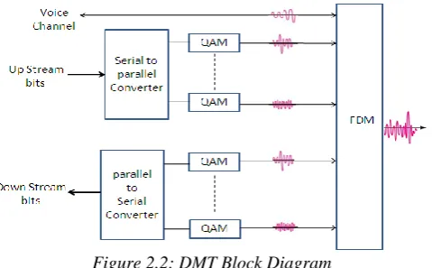
The Fig. 2.2 shows the block diagram of an ADSL transmitter and receiver during data transmission. This paper focuses mainly on the ADSL transmitter where the input data is called as the upstream data bit. The upstream data bits are sent through serial to parallel converter. The power level and number of bits in each sub channel is chosen to maximize data rate at a fixed bit error rate. One of the sub channels are dedicated to transmit a carrier signal that is used by the receiver for synchronization. The bit streams are modulated by baseband quadrature amplitude modulation (QAM) [12]. The outputs are mirrored and then modulated into higher frequencies using a 512 point inverse SR-FFT. The output of the inverse SR-FFT is guaranteed to be real.
Figure 2.2: DMT Block Diagram
C. MODIFIED SRFFT ALGORITHM
Page 203 www.ijiras.com | Email: [email protected] minimizes the complexity of system. The major metrics to
measure the performance of FFT structure of FFT algorithm and overhead of memory access. The cost of processor is reduced by reducing the number of twiddle factors, for this reason a number of FFT algorithms such as mixed radix & split radix have been proposed. Mixed radix is formed by 4-point butterflies which consist of 4 two 4-point butterflies without any multiplier. The modified algorithm of split radix requires fewer operations than mixed radix, but its irregular recursive structure hinders the efficiency on general purpose computers. This leads to the possibility of using different independent parts of the algorithm which will reduce the computational complexity. Hence split radix algorithm is used by combining the simplicity of radix-2 algorithm and lesser computational complexity of radix-4 algorithm. The Fig. 2.3 shows the block diagram of 512 point SR-FFT in DMT. The classic SR-FFT proposed by Duhamel and Hollman for 512 point requires 3076 real multiplications and 12292 real addition subtractions in 9 stages. Instead of using complex multipliers and adders, in this paper we proposed an idea of 512 point SR-FFT computation by using the three building blocks: 1. Dragonfly block, 2. Commutator block, and 3. ROM. Using theses blocks the computational result is achieved by just undergoing seven stages instead of 9 stages in MR-FFT. it requires 7 drangonfly blocks to perform SR-FFT 7 Commutator block for data scheduling and reordering and 6 ROM to store the twiddle factor. For this implementation only 336 DSP 48ES is used and thus achieve a higher speed with 1500 MSPS throughput [11].
Figure 2.3: General block diagram of SRFFT algorithm
In the figure 2.4 shows the detailed structure of SR-FFT. The incoming data is multiplexed onto the four parallel buses by retiming with a suitable lower clock and stored in four FIFO shift register for processing. The stage1 has to complete its computation within 64 clock cycles to achieve 1500MSPS. This reduces by using pipelined architecture to complete within 32 clock cycles. The twiddle factors are stored in ROM are read in pipeline and sent according to dragonfly stage. The input data is read from FIFO shift register in pipeline and provided to dragonfly block. Each dragonfly contains 4 L-Shaped dragon to process 16 data point at a time. This modified SRFFT has 4 point dragonfly and 2 point butterfly in earlier stage. At earlier stages the decomposition of the half and quarter length DFT leads to full split-radix structure. The 512 point SRFFT output is in bit reverse order and the output is stored in output is stored in output RAM by giving bit reverse ordered addresses. The dragonfly needs data in the
format of {x(n),x(n+N/2) and x(n+N/4), x(n+3N/4)}. To take dragonfly input in required format, data is stored in 4 input FIFO in the same order and data is provided simultaneously from FIFOs and given in pipeline to the next stages. To ease is data formatting, commutator is used. The commutator has FIFO to store data from and to the dragonfly. Data is stored in commutator one after the other and read at the same time for parallel operation. Commutator logic comprises of TDM of available data at individual stage. TDM employs writing of different stage outputs from previous stages and reading of the inputs to next stage. Commutator logic also includes reading of twiddles from a particular ROM. Input is taken in 16 parallel data buses and output is taken in 16 parallel data buses. In every stage, the first output is available after 12 clock cycle and the final output is available at the end of 44 clock cycle. Each taking total latency to 300 clock cycles. L – Shaped dragonfly requires 12 DSP blocks to compute three complex adder-subtractor and two complex multiplications. Since each stage contains four L-Shaped dragonfly 12 x 4 = 48 DSP blocks are utilized for one stage. Therefore for 512 point SR-FFT a complex 7 stage with 336 DSP blocks are used.
Figure 2.4: Detailed structure of SR-FFT
The real-time technique of FFT requires that: (1) the butterfly modules at a given stage can be constructed from one or more butterfly modules at the previous stage, and (2) a large portion of the butterfly modules can be constructed without the last few points of the input array. Most well-known FFT computation schemes (e.g., the radix-2, radix-4, prime-factor, and split-radix FFTs) satisfy these two requirements. Thus we will achieve the lowest number of arithmetic operation count to compute DFT of power of two sizes N.The figure 3.3 shows butterfly-structured module performing an L-point SR-FFT.The classic SR-FFT proposed by Duhamel and Hollman for 512 point requires 3076 real multiplication.Consider N-point DFT at an integer power power of 2(N=2r),An N-point DFT X[K] of data array x[n] is decomposed into one
2
N -point DFT x
2m[K] and two 4
N -point DFTs X4m+1[K] and X4m+3 [K]. Thus N-point DFT
becomes X(K)=
10 N
n x(n) W
N
Page 204 www.ijiras.com | Email: [email protected] =
1 2 0 Nm x(2m)W N
k
2m +
1 2
0 N
m x(2m+1) W N
k m 1) 2 ( X(K)=
1 2 0 N m x(2m)W N mk2 +
1 4 0 N m x(4m+1) W N k m 1) 4 ( +
1 4 0 Nm x(4m+3) W
N k m 3) 4
( (2)
Where W
N n =e N
n j2
& 0<
k
N
1
. The first term in eqn (1) represents in eqn (2)2
N -point DFT of the even
indexed data points in x(n) array
X2m(K)=
1 2 0 N
n x(2m) W 2 N
nk
The last two term in eqn (1) represents
4
N
point DFTs X(4m+1) (K) and X(4m+3) (K) with the twiddle factors are
1 4 0 N m x(4m+1)w N k m 1) 4 ( =
1 4 0 Nm x(4m+1) W
4 N
mk
W
N k = W
N k X
(4m+1) (K)
and
1 4 0 Nm x(4m+3) w
N
k m 3) 4 ( =
1 4 0 Nm x(4m+3) W
4 N nk W N k
3 = W
N k
3 X(4m+3) (K)
X(K)=
1 2 0 Nm x(2m)W N
mk 2 +
1 4 0 Nm x(4m+1)W N
k m 1) 4 ( +
1 4 0 Nm x(4m+3) W
N k m 3) 4 (
(3)
Where K varies from 0
K
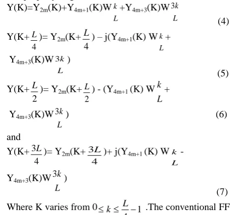
(N/4-1). In this figure 2.5,the DIT-SR-FFT structure has a horizontally reverse L-shape. This algorithm is a mixture of the radix-2 and radix-4 DIT-FFTs. The L -point DFT at the (r-j) th stage (L=2r-j) .The L-point DFT Y[K] is decomposed into one
2
Lpoint DFT
Y2m[K] at the (r-j-1) stage and two
4
Lpoint DFTs Y
4m+1[K]
and Y4m+3 [K] at the (r-j-2) th stage .Here Y2m[K] is defined for
K as 0
K
(L/2-1), Y4m+1[K] and Y4m+3 [K] are defined forK as 0
K
(L/4-1).Thus L-point DFT is derived using periodic property as given belowY(K)=Y2m(K)+Y4m+1(K)W
L
k+Y4m+3(K)W
L k 3 (4) Y(K+ 4
L)= Y
2m(K+
4
L) – j(Y
4m+1(K) W L k+ Y4m+3(K)W
L k 3 ) (5) Y(K+ 2
L)= Y 2m(K+
2
L) - (Y
4m+1 (K) W L k+
Y4m+3(K)W
L k
3 ) (6)
and Y(K+
4 3L)= Y
2m(K+
4
3L)+ j(Y4m+1 (K) W
L k -
Y4m+3(K)W L
k
3 ) (7)
Where K varies from 0 1 4
k L .The conventional FFT
is designed to obtain the complete frequency-band spectrum, hence an inherent assumptions are made that the input and output sequences with same array size. The modified algorithm implemented in this paper utilizes the data points available to construct the L-shaped modules results in further reduction in the number of arithmetic operations.
Figure 2.5: A butterfly-structured module performing an L-point SR-FFT
III. RESULTS AND DISCUSSION A. SIMULATION
Page 205 www.ijiras.com | Email: [email protected]
Figure 3.1: SR-FFT Processor output
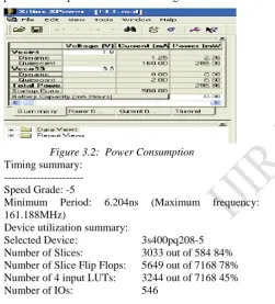
The power consumed by the processor for computation of 512 point SR-FFT processor is shown in Fig. 3.2
Figure 3.2: Power Consumption
Timing summary: --- Speed Grade: -5
Minimum Period: 6.204ns (Maximum frequency: 161.188MHz)
Device utilization summary:
Selected Device: 3s400pq208-5 Number of Slices: 3033 out of 584 84% Number of Slice Flip Flops: 5649 out of 7168 78% Number of 4 input LUTs: 3244 out of 7168 45%
Number of IOs: 546
IV. CONCLUSIONS
The Split radix FFT reduces the area on chip and also reduces the complexity by using radix2 and radix 4 algorithm. In this paper upstream direction of ADSL modem with DMT- G.Lite installation technique with SR-FFT is followed for the design to increase the speed of the processor. The hardware implementation for radix-2 FFT algorithm is the easiest but it is the least efficient. Split-radix 2/4 FFT algorithm is more efficient but its algorithm cannot produce regularity in hardware structure, thus not easily persuaded or controlled to implementation. The result of computation was made by
VHDL in XILINX ISE onVirtex 5 family. The multipliers and Adder/Subtractors were implemented by efficient interring the DSP48E blocks in order to obtain a faster design.
REFERENCES
[1] Byung G. Jo and Myung H. Sunwoo, "New Continuous-Flow Mixed-Radix (CFMR) FFT Processor Using Novel In-Place Strategy", IEEE Transactions on Circuits and Systems, Vol. 52, No. 5, 2005.
[2] Daisuke Takahashi, "An Extended Split-Radix FFT Algorithm", IEEE Signal Processing Letters, Vol. 8, No. 5, pp. 145-147, 2001.
[3] Gordon L. Demuth "Algorithms for Defining Mixed Radix FFT Flow Graphs", IEEE Trans Acoust, Speech, and Signal Processing, Vol. 37, No. 9, pp. 1349-1358, 1989. [4] Kyung L. Heo, Jae H. Baek, Myung H. Sunwoo, Byung
G. Jo, and Byung S. Son,2003 "New In-Place Strategy for a Mixed-Radix FFT processor", IEEE SOC Conference,
pp. 8 1-84.
[5] Lihong Jia, Yonghong GAO, Jouni Isoaho, and Hannu Tenhunen "A New VLSI-Oriented FFT Algorithm and Implementation",IEEE ASIC Conf., pp. 337-341, 1998. [6] Young-jin Moon, Young-il Kim Portable Internet system
research team Electronics and Telecommunications Research Institute (ETRI) Daejeon, Korea”, A Mixed-Radix 4-2 Butterfly with Simple Bit Revering for Ordering the Output Sequences”, ICA0T2006,pp1774-1778, 2006. [7] Zena Vastsa, Sumaya, “ VLSI Implementation of 2048
point FFT”, International Journal of Science and
Research(IJSR),ISSN(online): 2319-7064, 2013.
[8] Akshata.U, Gopika.D.K, Hameem Shanavas.I, “Hardware
implementation of Decimation in Time FFT”, MIT
International Journal of Electronics and communication Engineering Vol.3 No.1, Jan.2013, pp.39-42.
[9] C. Lin, Y. Yu, and L. Van, “A Low-Power 64-Point FFT/ IFFT Design for IEEE 802.11a WLAN Application”, Proc.
International Symposium on circuit and systems, pp. 4523- 4526, 2006.
[10]Yuan-Chu Yu and Yuan-Tse Yu, “Design of a High Effi- ciency Reconfigurable Pipeline Processor on Next Generation Portable Device,” Digital Signal Processing
and Signal Processing Education Meeting (DSP/SPE),
2013 IEEE, Aug 2013, pp. 42–47.
[11]R. Schur and J. Speidel, “An Efficient Equalization Method to Minimize Delay Spread in OFDM/DMT Systems,” in Proc. IEEE Int. Conf. on Comm., vol. 1, pp. 1–5, June 2001.