Abstract—Biometrics as a method for identification systems has been widely used for its robustness; one of its used is based on human palm. Palm has unique characteristics to be used in personal identification because of it features, namely palm print and hand geometry. This paper studied about biometrics of palm for identification system using the physical form of human hands, represented by the image of the palm. The methodology for palm recognition consisted of block-based line detection which dealing with palm print feature extraction process, and chain code which solved the hand geometric feature extraction. We combined those two respective features and recognized it using Dynamic Time Warping (DTW) method which was able to measure the distance between two different features. The result can be used for personal identification in authentication systems for information security.
Index Terms— biometrics, hand geometry, palm print, palm recognition.
I. INTRODUCTION
iometric authentication systems have certain advantages compared to traditional authentication systems such as password, pin, etc. The information security can be guaranteed because only authorized user who is able to access the personal information. The system required the person being authenticated to directly present their uniquely personal data at the moment of authentication [1]. Thus, biometric-based authentication system is a reliable and secure choice. Biometrics is a method to recognize human based on intrinsic features or characteristics that human has [2]. Physiological biometrics use unique physical characteristics of human such as fingerprint, face, palm print, iris, or DNA to identify user and has proven to be a powerful method for authentication systems [3].
Sonkamble, et al. explained that palm can be used as biometrics because it has unique features namely hand geometry and palm print [4]. Moreover, the palm of the hand provides a larger area compared to fingerprints, so the more distinctive features can be generated to improve the
Manuscript received January 5, 2012.
Dewi Yanti Liliana is a lecturer at Department of Computer Science, University of Brawijaya, Malang, East Java Provincial, Indonesia. (e-mail: dewi.liliana@ub.ac.id; dewi.liliana@gmail.com).
Eries Tri Utaminingsih is a graduate student of Department of Computer Science, University of Brawijaya, Malang, East Java Provincial, Indonesia.
performance of recognition. The feature of hand geometry is relatively simple and easy to use but it is not invariant due to a period of time. Meanwhile, feature of palm print is specific and can only be generated from a high resolution image, but it is hard to be faked and also invariant because it is quite stable due to a little change in a long time [5, 6].
In this paper we combined the strength of palm print and hand geometry features to enhance the accuracy rate of the palm recognition system. We used block-based line detection for palm print feature extraction. The extracted features were the mean and standard deviation of each block. Consecutively, hand geometry feature was extracted using chain code method which was able to form a contour of an object by detecting the line of palm in eight compass directions. The combined features were then recognized using Dynamic Time Warping (DTW) method which was able to measure the distance between two different feature vector’s lengths.
Personal identification system is feasible to be developed towards an online system and applied for a specific application fields, such as attendance applications, medical records application, security applications, forensic applications, and other applications.
II. PREVIOUS RESEARCH
Several studies on personal-recognition system have been developed using palm as a single feature. Zhang, et al. developed an online identification system by implementing Gabor filter to obtain palm print feature information [7]. Duta, et al. separated set of feature points along the main line of palms and calculates a score that fits between a set of related features of the two hands [8]. Li, et al. used Fourier transformation to obtain the features of the palm [9]. Wu, et al. formed a line vector features (LVF) using the gradient magnitude and orientation of points on the main line of the palm to extract the palm print features [10]. Jain and Duta employed deformable hand shape matching to verify user [11]. Kumar, et al. incorporated two hand geometry features; palm print and hand geometry to extract salient features and verified user based on the fusion features [12]. The main differences between this research and the previous one done by Kumar et al. were in the feature extraction and recognition process. We performed block-based line detection and chain code for palm print and hand geometry feature extraction, respectively. The recognition was done using dynamic time warping which was able to measure the distance between two
The combination of palm print and hand
geometry for biometrics palm recognition
Dewi Yanti Liliana, Eries Tri Utaminingsih
data vectors which had different length, while in Kumar et al, used only a simple matching score technique.
III. BIOMETRICS PALM RECOGNITION SYSTEM
Biometrics palm recognition is a multimodal biometrics system that combined two features; palm print, and hand geometry for personal identification. It used only a single hand image to capture those two features simultaneously to form a new feature. The new feature was then used to recognize the user. General stages of palm recognition system are as follows: step 1. Preprocessing, is a stage to process the raw data into a specific target area or Region of Interest (ROI).
step 2. Feature extraction, concurrently two features (palm print and hand geometry) are extracted using specific methods. step 3. Palm recognition, in this stage the extracted features will be compared with the database to find the matching user with the test features.
A. Preprocessing
Preprocessing is aimed to change the raw data, to assist computational capabilities in feature extraction as well as to reduce noise. We used digital image processing techniques which intended to change the intensity of image pixels to produce a more suitable form of data for subsequent operations. In preprocessing, the image captured by the sensor will be normalized in order to prepare the feature extraction. Standard techniques were used in the preprocessing, including: grayscaling, thresholding using Otsu method [12], Region of Interest (ROI) determination, intensity normalization, scaling, median filter, and the delimitation of the area. Fig. 1 gives the example of image preprocessing steps.
(a) (b)
(c) (d)
Fig. 1. Preprocessing steps: (a) original palm image; (b) grayscaling; (c) thresholding; (d) Region of Interest (ROI).
B.Palm print Feature Extraction
Palm print consists of several lines, namely: main lines, wrinkle lines, delta points, and minutiae feature [3]. Palm print feature extraction is dealing with a quantization characteristics
of the image into a set of corresponding feature values. Feature values were extracted using block-based line detection. The preprocessing image that has undergone line detection was divided into several blocks. We took standard deviation of each block as palm print feature value.
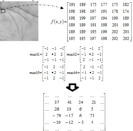
Line Detection Using Convolution Mask
We used convolution mask for line detection process [13]. Line detection was done by matching some image areas with a mask which showed a different part of image: vertically, horizontally, or diagonally. We replaced the original center pixel value with the maximum value gained from the convolution mask process. The convolution formula can be found in equation 1.
Ri > Rj , i≠j (1)
where R is the convolution value obtained from eq. 2:
∑
=
=
91
i i i
z
w
R
(2)i = 1,…,9 is the number of mask pixels, wi is the
corresponding mask value, and zi is the gray level of image
pixel. We used 3x3 mask pixels with four directions; horizontal, diagonal +45°, vertical and diagonal -45°. Fig. 2 gives the example of convolution mask process. Each 3x3 image pixels was scanned and masked using four convolution masks, and the result (the maximum convolution value) replaced the original gray level value.
Fig. 2. The illustration of line detection using convolution mask.
Block-based Feature Extraction
Blocking process divided image into several blocks with certain size. For each block we got the mean µ and standard deviation σ using equation 3.
∑
= −
=
Mi i
x
M
1 1
−
−
−
−
+
=
)
1
,
(
)
1
,
1
(
)
,
1
(
min
)
,
(
)
,
(
j
i
j
i
j
i
v
u
d
n
m
base i jγ
γ
γ
γ
where M denotes the number of pixels in a block, and x is the pixel value. From mean µ, we got standard deviation σ from equation 4:
(
)
21 1 2 1 − =
∑
= − M i i x M µσ
(4)
Palm print feature vector V was formed from standard deviation of all blocks; V =
(
σ1,σ2,σ3,...,σN)
, where σi denoted standard deviation of block-i and N denoted the total blocks.C. Hand geometry Feature Extraction
Before we extract the hand geometry feature, some preprocessing must be done on an image to reduce noise. The preprocessing steps were: scaling for image normalization; median filter for noise reduction; and area delimitation to get the perimeter of hand geometry. We used nearest neighbor checking to separate the object area from the background. The object area had 255 pixel values, while backgrounds were 0 values.
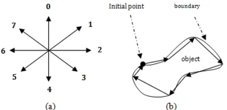
Afterwards, we employed chain code method to find the boundary by encoded the contour of an object [14]. Chain code specified the direction of each pixel and kept it in an array. This code was known as Freeman chain codes which used 8 directions clockwise [15]. The codes came from trajectory traced by the centers of adjacent boundary elements in an image array. The direction of each pixel coding can be seen in Fig. 3.
Fig. 3. The direction of chain codes: (a) clockwise from 0 point; (b) the representation of object boundary by chain code.
Chain code operation is started from the initial point, moving forward, clockwise. Each boundary pixel is coded according to its chain code respectfully. Fig. 4 shows the example of chain code operation of an object.
D. Palm Recognition with Dynamic Time Warping
In the recognition phase we measure the similarity using a matching score of palm print and hand geometry features between test data and the data stored at the training database. The matching score is obtained using Dynamic Time Wrapping (DTW) distance. The higher matching score, the more similar the data. In advance, features must be normalized and scaled prior to the DTW process. The process of feature normalization and scaling as prerequisites of DTW is explained as follows.
1 2 2 2 2 2
0 2 2 3
0 3 2 2
7 4
7 4
6 6 6 6 6 6 6 6 6 6 4
Fig. 4. An example of object boundary coding with chain code, starting from the initial point (shaded cell), resulting an array of chain code A = 22222332244466666666667700221
Normalization
The purpose of data/feature normalization is to make the feature has zero mean. Feature normalization of original data is using equation 5.
x X X X σ − = ∧ (5)
whereX,X,X,
σ
x∧
denote the original feature vector, normalized feature vector, feature mean, and standard deviation, respectfully.
Scaling
Scaling is done to the data in order to have some certain interval with upper bound S=0 and lower bound R=1 (interval = [0,1]). The equation 6 is used for scaling the feature vectorX∧ .
(
S R)
R XX X X
X ∗ − +
− − = ∧ min max min (6)
Dynamic Time Warping (DTW)
DTW (Dynamic Time Warping) is a method to measure a distance between two time series. The advantage of DTW is the ability to measure a distance between two different vector lengths. The distance between vectors is measured by finding the optimal warping path of those vectors. The measurement is using dynamic programming method using the equation 7.
D
(
U,V)
=γ(
m,n)
∞
=
∞
=
∞
=
∞
=
0
,
(
0
,
)
,
(
0
,
0
)
0
,
(
,
0
)
)
0
,
0
(
γ
γ
γ
γ
(7)(i=1,2,3...m; j=1,2,3...n) initial point
D(U,V) is the distance matrix. The value in column (i, j) is the sum value of warping line of the column (1, 1) to (i, j). The column with a value is called the cumulative distance matrix. Here is a sample of cumulative distance matrix:
0 3 6 0 6 1
2 4 5 21 25 41 42
5 29 8 6 31 26 42
2 33 9 22 10 26 27
5 58 13 10 35 11 27
3 67 13 19 19 20 15
Fig. 5. The illustration of cumulative distance matrix between vector U={2,5,2,5,3}, and vector V={0,3,6,0,6,1}
The shaded cell in fig. 5 is the smallest value in each column. We get the total cumulative distance or the DTW value at the last column. This value represents the distance between two feature vectors (matching score). The recognition will undergo the same process; each feature vector in the database is compared with the test data and the highest matching score is recognized as the user’s feature.
IV. RESULT AND DISCUSSION
The experiment was carried out on a dataset of hand image used in [16]. The dataset contained images belong to 50 people. Each person registered the image of the left hand palm for 4 times, so there were 200 images on the database. All data was divided into two respective training and testing data, equally. Fig. 6 shows the example of training and testing data.
(a) (b)
Fig. 6. Example of: (a) training image; (b) testing image (the original image size is 640x480 pixels)
Testing was conducted on 100 testing data using three methods, namely: palm print biometrics; hand geometry biometrics; and the combination of palm print and hand geometry. The test results that determine the accuracy rate of each method can be seen in table 1.
TABLEI
THE ACCURACY RATE OF THREE DIFFERENT METHODS
Methods/ Test data
Palm print biometrics
Hand geometry biometrics
Combination of palm print & hand
geometry
user match 69 51 89
user not match 31 49 11
Table 1 shows that the combination method has the highest user recognition performance, followed by palm print biometrics and hand geometry biometrics. Fig. 7 shows the accuracy of these three methods in which the combination of palm print and hand geometry has the highest accuracy rate of 89%. Data that are not identified correctly due to the different brightness levels, the presence of noise in the background, and the position of the hand when the image was taken.
Fig. 7. The accuracy rate of three different methods.
V. CONCLUSION AND RECOMMENDATION
The combination of palm print and hand geometry can be the best method for palm recognition. From the experiment conducted, the system has the highest accuracy rate compared to both of single feature palm print method or single feature hand geometry method. Therefore, we recommend the use of the combination method for palm recognition in biometrics authentication systems.
Future works might be done in feature extraction techniques, either in palm print feature or hand geometry feature extraction to increase the accuracy rate. Moreover, enhancement can be done in the recognition method, and compared the results with DTW method which we used in this research.
REFERENCES
[1] M. Kabatoff, J. Dougman, BioSocieties, Pattern Recognition: Biometrics, Identity and State – An Interview with John Dougman, London School of Economics and Political Science, London UK, 2008, pp. 3, 81, 86.
[2] N.K. Ratha, J.H. Connell, and R.M. Bolle, “Enhancing Security and Privacy in Biometrics-based Authentication Systems”, IBM systems Journal, vol. 40, 2001, pp. 614-634.
[3] M.A. Dabbah, W.L. Woo, and S.S. Dlay, “Secure Authentication for Face Recognition”, presented at Computational Intelligence in Image and Signal Processing, CIISP 2007, IEEE Symposium, 2007.
[4] S. Sonkamble, R. Thool, and B. Sonkamble, “Survey Of Biometric Recognition Systems And Their Applications”, Journal of Theoretical and Applied Information Technology, Vol 11. No. 1, 2010.
[5] X. Wu, K. Wand, and D. Zhang, “Fuzzy Directional Element Energy Feature (FDEEF) Based Palmprint Identification”, Proceeding 16th International Conferences on Pattern Recognition, 1, 2002, pp. 95-98. [6] A. Kumar, D. C. M. Wong, H. C. Shen, and A. K. Jain, Personal
Verification using Palmprint and Hand Geometry Biometric, 2004. Available: http://www.cs.ust.hk/.
[7] D. Zhang, Wai-Kin Kong, J. You, M. Wong, “Online Palmprint Identification”, IEEE Transaction on Pattern Analysis and Machine Intelligence, 25(9), 2003.
[8] N. Duta, A.K. Jain, K.V. Mardia, “Matching of Palmprints”, Pattern Recognition Letters, 23, 2002, pp. 477-485.
[9] W.X. Li, D. Zhang, S.Q. Xu, “Palmprint Recognition Based on Fourier Transform”, Journal of Software, 13(5), 2002.
[10] X.Q. Wu, K.Q. Wang, and D. Zhang, An Approach to Line Feature Representation and Matching for Palmprint Recognition, 2004. Available at http://www.jos.org.cn/10010-9828/15/869.htm.
[11] A.K. Jain, N. Duta, “Deformable Matching Of Hand Shapes For User Verification”, International Conference on Image Processing, Vol. 4, 1999, pp. 24-28.
[12] N. Otsu, “A threshold selection method from gray-scale histogram”, IEEE Trans. Syst., Man, Cybernetics, vol. 8, 1978, pp. 62-66. [13] R.C. Gonzales, R.E. Woods, Digital Image Processing. 2nd Ed. Upper
Saddle River, N. J.: Prentice-Hall, Inc, 2002.
[14] H. Freeman, Computer Processing of Line-Drawing Images, ACM Computing Surveys, Vol. 6, No.1, 1974, pp. 57-97.
[15] S. Madhvanath, G. Kim and V. Govindaraju, “Chain code Contour Processing for Handwritten Word Recognition”, IEEE Transactions on Pattern Analysis and Machine Intelligence, Vol. 21, No. 9, September, 1999.
[16] IKG. Darma Putra, Sistem Verifikasi Biometrika Telapak Tangan dengan Metode Dimensi Fraktal dan Lacunarity, Teknologi Elektro, 8(2), PSTE UNUD, 2004, pp. 1-6.
Dewi Yanti Liliana received the bachelor degree in informatics from
Sepuluh Nopember Institute of technology, Surabaya, Indonesia in 2004. She received the master degree in computer science from University of Indonesia, Depok, Indonesia in 2009.