e
-ISSN: 2278-067X,
p
-ISSN : 2278-800X, www.ijerd.com
Volume 5, Issue 10 (January 2013), PP. 41-46
Performance Improvement for Vessel Nesting
Soon-kak Kwon
1, Seung-hwan Kim
21,2Dept. of Computer Software Engineering, Dongeui University, Korea
Abstract:- This paper presents the performance improvement method for vessel nesting processing. Within nesting processing, three functions are inserted. Trim connecting two objects is to improve the nesting processing speed. Polyline creating a single object from multiple selecting objects is also to improve the nesting processing speed. Overline removing the overlapped parts is to improve the speed and save the product resources.
Keywords:- Nesting, Trim, Overline, Polyline
I.
INTRODUCTION
This Nesting is processed after the end of each part of the design work for vessel. In general, the nesting process is complete, then the cutting path of various materials will be set and numerical code to control the machine tools with processing conditions will be generated.
Nesting is depending on the applied fields and the different constraints. Common goal is that the scrap ratio should be minimized while placing the material in a given area without overlap. Until now, the manual, semi-automatic, and automatic nesting methods are used in a wide range in a variety of fields ranging, but the point of view of the placement algorithm has been treated as NP(Nondeterministic and Polynomial time)-complete problem : impossible to find the optimal solution in a limited time.
There are some methods for nesting algorithm. Automatic nesting [1] using a rule-based heuristic approach to improve the layout efficiency was presented. A quick location and movement algorithm [2] was proposed to solve the situation of irregular shapes nested on multiple irregular sheets. Also incorporating method [3] of space encoding scheme and a greedy method for placing parts was presented. Some paper [4] showed that the intelligent CAN(computer-aided nesting) system could nest both regular and irregular parts. There are many courses and skills in nesting processing. Some processes, which are not necessary during the work, come up and interrupt the courses of nesting such as losing face of processes and missing some delicate parts of the work. For fixing such problems, the nesting is proposed to provide convenience and better work performances. Three functions are trim, polyline, and overline. Those can improve the nesting processing speed and save the product resources.
The remainder of this paper consists of five sections. Section II describes the definitions of trim, polyline, and overline. Section III presents the algorithm for three nesting functions. Section IV shows the implementation results for proposed method. Finally, Section V concludes this paper.
II.
DEFINITION
OF
TRIM,
POLYLINE,
AND
OVERLINE
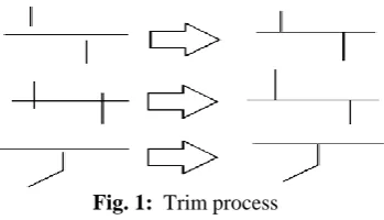
Trim connects an object to the other one by finding an intersection point between two objects. Also it gets rid of unnecessary work that is not meant. This course will improve the nesting processing speed.
Fig. 1: Trim process
Fig. 2: Polyline process
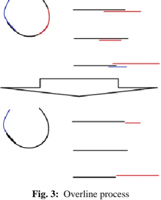
Overline removes overlapped parts, which are unnecessary, in an object so that the processing speed can be improved and the product resources can be saved.
Fig. 3: Overline process
III.
ALGORITHM
OF
PROPOSED
FUNCTIONS
In order to implement the proposed functions, some kinds of algorism are used. To the following paragraphs, two most typical algorithms are explained: Is one point on a straight line? Is one point on ARC line? - Judge whether a point exists on the Line.
.
Fig. 4: Straight line
If there is one point on a straight line, it will come up with two different kinds of problems. 1) The problem is that three points are on a straight line when three points are given.
2) The problem is that one point is on a straight line when the only one straight line is given.
Straight line equation is as follows. a x + b y + c = 0
If any point (px, py) is the point on a straight line, when substituting this point in a straight line, the equation should be satisfied.
Therefore, it can be described as follows. a * px + b * py + c = 0
⇒ (px,py) is on a straight line. ⇒ return rist = 1. a * px + b * py + c != 0
⇒ (px,py) is not on a straight line. ⇒ return rist = .
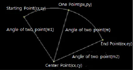
- Judge whether a point exists on the ARC.
Points on the ARC (the starting point (sx, sy), end point (ex, ey)) of the circle can be identified.
Calculate the angle between each points and determine the location of the point on ARC range with considering clockwise or counterclockwise.
1) First determine whether the ARC's direction, clockwise or counterclockwise.
2) Calculate the angle (m1) formed by center and the starting point of the ARC, and the angle (m2) formed by center and the end point of the ARC.
3) Calculate the angle formed by center and any point in ARC.
4) Judge whether any point is on ARC range considering the direction and angle .
The case of clockwise :
♧ Case of m2<>
⇒ if m2 < m < m1, then a point is on ARC. In other cases, the point is not on ARC.
♧ Case of m1<>
⇒ if m1 < m < m2 a point is on ARC. In other cases, the point is not on ARC.
Fig. 5: Clockwise space
The case of counterclockwise:
♧ Case of m1<>
⇒ if m1 < m < m2, then a point is on ARC. In other cases, the point is not on ARC.
♧ Case of m2<>
⇒ if m2 < m < m1 a point is on ARC. In other cases, the point is not on ARC.
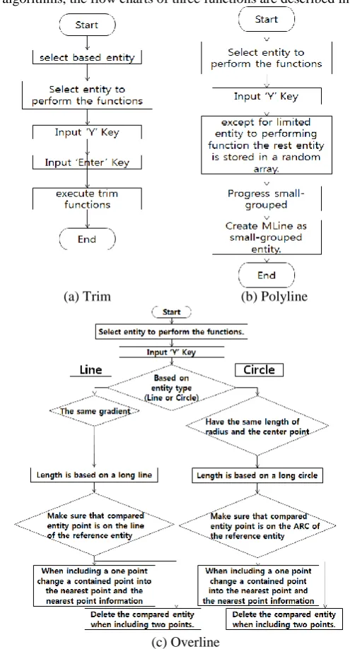
By using above algorithms, the flow charts of three functions are described in Fig . 7.
(a) Trim (b) Polyline
(c) Overline
Fig. 7: Flow chart of proposed functions
IV.
IMPLEMENT
RESULTS
OF
PROPOSED
METHOD
The proposed nesting functions are implemented in the company nesting software, that is, CADWIN. Fig. 8 and Fig. 9 show the trim function. Before trim processing, the lines and circles are not connected. After trim, we can see that the objects are connected.
Fig. 9: After trim
Also, Fig. 10 and Fig. 11 show the polyline processing.
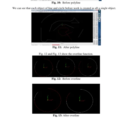
Fig. 10: Before polyline
We can see that each object of line and circle before work is created as all a single object.
Fig. 11: After polyline
Fig. 12 and Fig. 13 show the overline function.
Fig. 12: Before overline
When the buttons for each function are activated, a brief explanation is followed how to use the bottom. The object is supported from object type classified as line, circle.
V.
CONCLUSIONS
The additional functions are added to improve the vessel nesting performance. Three functions of trim, poyline, and overline are necessary to reduce the nesting speed and save the product resources. We have implemented the functions on the real nesting system. Also, the proposed method can get great potential to various applications by improving advantages such as its algorithm, functions, and properties.
ACKNOWLEDGMENT
The authors would like to thank Cadwin System, Ltd for providing nesting software, CADWIN*NEST. Corresponding author : Soon-kak Kwon ([email protected]).
REFERENCES
[1]. Y. Kim, K. Gotoh, and M. Toyosada, “Automatic two-dimensional layout using a rule-based heuristic algorithm,” Journal of Marine Science and Technology, vol.8, pp. 37–46, May 2003.
[2]. W.-C. Lee, H. Ma, and B.-W. Cheng, “A heuristic for nesting problems of irregular shapes,” Computer-Aided Design, vol.40, pp. 625–633, May 2008.
[3]. H. Ma, C.-C. Liu, “A fast nesting of 2-D sheet parts with arbitrary shapes using a greedy method and semi-discrete representations,” IEEE Transactions on Automation Science and Engineering, vol.4, pp. 273–282, April 2007.