ISSN (e): 2250-3021, ISSN (p): 2278-8719
Vol. 08, Issue 6 (June. 2018), ||V (II) || PP 16-25
Performance of electronically controlled automotive engine
cooling system using PID and LQR control techniques
Mostafa Mohamed
1,M.H. Shedid
2,S. El-Demerdash
3,M. Fatouh
4 1(Automotive and Tractors Engineering Department, Faculty of Engineering, Mattaria Helwan University, Cairo)
2(Mechanical Power Engineering Department, Faculty of Engineering, Mattaria Helwan University, Cairo)
Corresponding Author: Mostafa Mohamed
Abstract:
The cooling system of internal combustion engine plays a major role in a vehicle performance. In the present work, a proposed electronic controller for the cooling system is introduced and modelled mathematically to control the engine coolant temperature using a controllable electric water pump and radiator fan. Proportional Integral Derivative (PID) and Linear Quadratic Regulation (LQR) control techniques are considered to design the cooling system controller both the coolant flow rate and radiator fan speed are used to control the engine coolant temperature. The Worldwide Harmonized Light Vehicles Test Cycle (WLTC) is used to test the proposed controller based on mathematical simulation using MATLAB/SIMULINK software. The generated numerical results are presented in thetime domain and compared with theconventional cooling system. The results showed that the proposed controller enhanced the engine coolant temperature either during warm-up or steady-state operation over that of theconventional cooling system.Keywords
-
Electronic Engine Cooling, PID, LQR, Modelling, Controller--- --- Date of Submission: 28-05-2018 Date of acceptance: 11-06-2018 --- ---
I.
INTRODUCTION
Active control for the cooling system of theinternal combustion engine is an essential topic to enhance the vehicle performance during the different operating modes. Although the conventional automotive cooling system has proven satisfactory for many decades, servomotor controlled cooling components have the potential to reduce the fuel consumption, parasitic losses, and tailpipe emissions [1], Wagner et al. [2] mentioned that the advanced controllable cooling system technologies provide 1–3% fuel reduction through lower parasitic losses, minimizing temperature fluctuations and lower emissions. These controllable systems replace the conventional wax thermostat valve with a controllable position smart valve. Also, and the mechanical water pump and radiator fan are replaced with electric and/or hydraulic driven actuators. These changes in the cooling system components must decouple the water pump and radiator fan from the engine crankshaft, Lodi, F.S, that leads to avoiding the over/under cooling demand by controlling the pump speed using robust control strategy [3]. Cho et al. [4] investigated the cooling system with controllable electric water pump in a class-3 medium duty diesel engine truck. Their results showed that it is possible to reduce the radiator size by replacing the mechanical pump with an electrical one. Chalgren and Allen [5] improved the engine coolant temperature form a light duty diesel truck using a controllable cooling system designed based adaptive control technique. Chastain and Wagner [6] pursued a lumped parameter modeling approach and presented multimode thermal models that estimate the internal engine temperature and the findings demonstrated that set point temperatures can be maintained satisfactory while minimizing power consumption which ultimately affects fuel economy.
results demonstrate that the three-way valve had the best performance and cooling system power consumption. The two-way valve and valve absent configurations were very similar in performance, leading to the conclusion that a two-way valve might be eliminated entirely from the cooling system.
Hoon, et. al. [11] indicated that the cooling system with the electric pump dramatically reduces the pump power consumption during the FTP 74 driving schedule and that radiator can be downsized by more than 27% of the original size under grade load condition.The forging review revealed that most of the previous research focused on the engine cooling performance due to thereplacement of the conventional system by theelectric water pump and electric thermostat without afocus on the effect different type of control strategies and dispense with the thermostat. In this work, two control strategies are presented to actively regulate the coolant temperature ininternal combustion engines due to designed operating temperature. The proposed control strategies have been verified by simulation during standard test drive cycle (WLTP), the cooling system model is presented to describe the thermal system dynamics without the thermostat valve.
This paper focuses the attention on the improvement of system thermal behaviour by using different control strategies on the electric water pump and electric cooling fan.
II.
ENGINE
COOLING
SYSTEM
MODELING
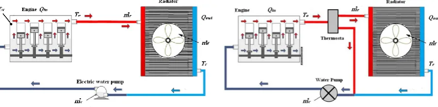
The mathematical model is proposed to describe the thermal behaviour of the engine cooling system to investigate the characteristics of the engine cooling system. The electrically controlled engine cooling system is shown in Fig. 1a, in which the radiator is equipped with a variable speed electric cooling fan; the mechanical thermostat valve has been removed from the cooling circuit.
Figure 1a. Electrically controlled cooling system layout.Figure 1b. Conventional cooling system layout.
The conventional belt is driven water pump also replaced with a variable speed electric water pump. The additional sensors in the system are used such as cylinder wall temperature sensor and radiator coolant outlet temperature sensor. The engine cooling system model includes two base sets of control parameters named the engine coolant temperature (𝐓𝐞) andthe radiator coolant temperature(𝐓𝐫). The engine coolant temperature
dependents on the heat transfer rate from the engine to the cooling system (𝐐𝐢𝐧) and the coolant mass flow rate
(𝐦 𝐫), which depends on water pump speed and the thermostat. The radiator coolant temperature dependents on
an uncontrolled heat rate (𝐐𝐨𝐮𝐭) due to the radiator radiation heat transfer rate and the forced air mass flow rate
(𝐦 𝐟), which is a function of electric fan speed. To facilitate this model, the effect of the junction node
temperature, the energy added by pump and heat transfer rate from engine to coolathe nt by radiation are neglected. Applying energy balance on the engine cooling system yields [7]:
𝐶𝑒𝑇 𝑒 = 𝑄𝑖𝑛 − 𝑚 𝑟𝐶𝑝𝑐 𝑇𝑒− 𝑇𝑟 (1) 𝐶𝑟𝑇 𝑟= −𝑄𝑜𝑢𝑡 + 𝑚 𝑟𝐶𝑝𝑐 𝑇𝑒− 𝑇𝑟 − 𝑄𝑓𝑎𝑛 (2)
𝑄𝑓𝑎𝑛 = 𝜀𝑚 𝑓𝐶𝑝𝑎 𝑇𝑟− 𝑇∞ (3)
Where 𝐓𝐞(𝑡) and 𝐓𝐫(t) are the coolant temperature at engine outlet and the coolant temperature at the
radiator outlet, respectively. (𝐓∞) and (𝛆) represent the ambient temperature and radiator effectiveness,
respectively. (𝐂𝐞) and (𝐂𝐫) are the engine block heat capacity and the radiator heat capacity, while (𝐂𝐩𝐜) and
(𝐂𝐩𝐚) are the coolant specific heat and the ambient air specific heat, respectively. (𝐦 𝐫) and (𝐦 𝐜) are the coolant
mass flow rate through the radiator and the coolant mass flow rate through the heater, respectively. (𝐐𝐢𝐧) and
(𝐐𝐨𝐮𝐭) are the heat energy transfer rate to the coolant from the engine and uncontrollable radiator heat loss rate
through the air flow. The flow rates though the radiator (𝐦 𝐫) and bypass circuit are determined by the thermostat
valve position (𝐇𝐭), which equals unity in the present work and the coolant mass flow rate (𝐦 𝐜), which can be
adjusted by pump speed, i.e.
Qin = 𝑈𝐴 (𝑇𝑤− 𝑇𝑒) (5)
Where (𝐔) the overall heat transfer coefficient from engine wall to the coolant and (𝐀)A is the total cylinder wall surface area. Since the wall temperature varies with the crank angle, engine speed and engine load, it is difficult to simulate the detailed Tw. Therefore, Tw is represented as an experimental formula for the compression and expansion strokes, which can be expressed as [12]:
𝑇𝑤= 1408.7 − 3021 .9 𝑁𝑒+ 0.00472 𝑁𝑒2− 2640.1 𝑃𝑚 + 1423.4 𝑃𝑚2+ 9.8922 𝑁𝑒𝑃𝑚 (6)
Where 𝑁𝑒the engine is speed and 𝑃𝑚 is the intake manifold pressure. The heat absorbed by the concentric tube
cooling heat exchanger radiator in the cooling system, (Qout) may be described as: 𝑄𝑜𝑢𝑡 = ℎ𝐴𝑠∗ (𝑇𝑏− 𝑇∞) (7)
𝑇𝑏 = 𝑇𝑒+ 𝑇𝑟 /2 (8)
Where (𝐡) the convective heat transfer coefficient from radiator tubes to the ambient air (𝐀𝐬) is the
surface area of radiator tubes. (𝐓𝐛) is the fluid bulk temperature, respectively.The mechanical water pump speed
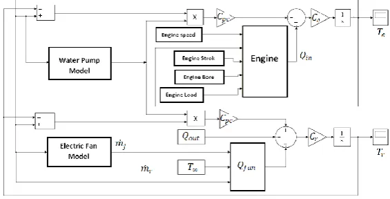
is a function of the engine speed due to direct connection and the belt ratio between pulleys of crankshaft and water pump, The belt ration is equal (1.1) in this work. These equations have been plugged together into SIMULINK software to obtain a computer program simulating of the engine cooling system as shown in Fig. 2. The SIMULINK model of the cooling system has been used to compare the performance of the conventional engine cooling system with the electrically controlled engine cooling system under different operating conditions.
Figure 2. Electrically controlled engine cooling system model in MATLAB/SIMULINK
The SIMULINK model required a sub model for each main component of the cooling system which integrated into the overall model to simulate efficiently the whole system. The simulations of sub model were developed for each component based on themathematical representation of their heat and fluid flows. The generated heat in the engine is a function of the engine torque and speed while the electric water pump that provides the coolant mass flow rate functions in the coolant density, pump specifications,and speed. The corresponding coolant mass flow rate (𝐦 𝐜) can described as:
𝑚 𝑐= 2𝜋. 𝜌𝑐. 𝑟𝑑. 𝑏. 𝑉 (9)
Where (𝝆𝒄) is the coolant density, (𝒓𝒅) is the pump impeller radius, (b) is the pump inlet impeller width and
(V) is pump inlet radial velocity which is controllable variable in this work. The electric fan model generates the air mass flow rate related to the controller output signal and the corresponding radiator air mass flow rate (𝐦 𝐟) can described as:
𝑚 𝑓=𝜌𝑎. 𝐴𝑓. 𝑟. 𝜔𝑓 (10)
Where (𝜌𝑎) is the ambient air density, (𝑟) is the fan radius and (Af) is the area exposed to radiator fan which
rotate with angular speed (𝝎𝒇) which is controllable variable in this work. The usage of electric pump enables
the reduction of the power consumption by optimizing coolant flow control. In addition, an electric coolant pump has higher efficiency than the mechanical pump [4, 11], The performance maps that consist of pressure drop, flow rate, pump speeds, and efficiencies, were used in order to calculate pump power consumption. Based on these map data, the pump power consumption was calculated using the following equation.
𝑷 = 𝜼. 𝑸𝑷. ∆𝑷 (11)
Where (𝑃) is pump power consumption, (η) pump Efficiency, (𝑄𝑃) volumetric flow rate, (ΔP) pressure Drop
III.
DESIGN
OF
ENGINE
COOLING
SYSTEM
CONTROLLER
Fig. 3 shows a schematic diagram of the proposed cooling system controller used in this work. The controller is designed based on two control strategies PID and LQR to generate the command control signals to control the electric water pump and electric radiator fan depending on the engine load at different operation conditions.
The measurements are radiator coolant temperature (𝑻𝒓) engine coolant temperature (𝑻𝒆), coolant mass
flow rate (𝒎 𝒄), cylinder wall temperature (𝑻𝒘) and ambient air temperature. (𝑻∞) These signals are the input
signals to the controller.
Figure 3. Block diagram of the proposed engine cooling system controller. The main objectives for both PID and LQR are:
1- Ensure that the actual temperatures of the engine block and the radiator block track the desired temperatures.
2- Reduce the duration of an engine cold start by rapidly bringing the engine to the desired operating temperature.
3- Minimize the working duration of the cooling fan and cooling pump.
3.1 PID CONTROL STRATEGY
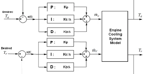
Fig. 4 indicate the block diagram of the PID controller designed in future work, the PID gains are obtained through trial and error to make the system stable and to keep the load at exactly the engine coolant and radiator coolant temperature set point, which selected due to engine performance and geometry and equal to the engine coolant operating temperature.
Figure 4. Proposed PID controller diagram for ICE cooling system
To do this, the model output signals is feedbacked to the controller; to adjust the controller output command signals for the water pump and radiator fan. The controller output of conventional PID controller is given as in equation 12.
𝑢 𝑡 = 𝐾𝑃+ 𝐾𝐼 𝑒 𝑡 𝑑𝑡 + 𝐾𝐷 𝑑𝑒 (𝑡)
𝑑𝑡 (12)
Table 1. PID Controller Gain Values.
3.2 LQR CONTROL STRATEGY
The block diagram of the optimal control theory using the LQR control technique is shown in Fig. 5 This control technique is used for multi-input, multi-output (MIMO) control systems. However, the cooling system is MIMO system, so the LQR is more suitable control technique to use. The cooling system in state space form is given by: 𝑥.= 𝐴 𝑥 + 𝐵 𝑢 𝑦 = 𝐶 𝑥 Where: 𝑥.= 𝑇𝑒. 𝑇𝑟. 𝑢 = 𝑚𝑐. 𝑚𝑓. 𝑦 = 𝑇𝑒 𝑇𝑟 A = −𝐶𝑝𝑐 𝐶𝑒 𝑚 𝑐 𝐶𝑝𝑐 𝐶𝑒 𝑚 𝑐 𝐶𝑝𝑐 𝐶𝑟 𝐻𝑡𝑚 𝑐− 𝐶𝑝𝑎 𝐶𝑟 𝑚𝑓 . −𝐶𝑝𝑐 𝐶𝑟 𝑚 𝑟 B = − 𝐶𝑝𝑐
𝐶𝑒 𝑇𝑒− 𝑇𝑟 0
𝐶𝑝𝑐 𝐶𝑟 𝑚 𝑐𝐻𝑡 𝑇𝑒− 𝑇𝑟 − 𝐶𝑝𝑎 𝐶𝑟 𝑚𝑓 . (𝑇 𝑒− 𝑇∞)
C = 1 0
0 1
LQR controller is a state regulating controller, which means it acts on anerror in the system’s internal states as opposed to the system’s outputs. The controlsignal (u) drives the system’s states to zero by minimizing the cost function
𝐽 = 𝑥∞ 𝑇
0 𝑄𝑥 + 𝑢
𝑇𝑅𝑢 (13)
The weighting matrices used to tune the controller are Q and R, for a given system, 𝑥. = f (𝑥,𝑢) and a
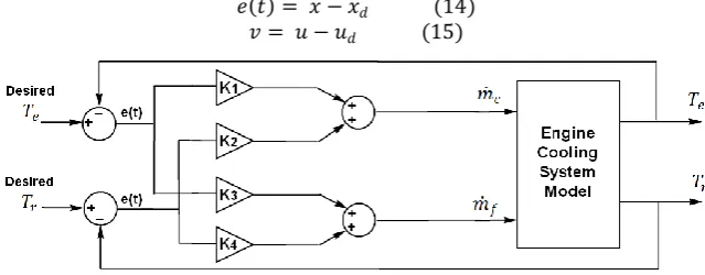
feasible trajectory (𝑥𝑑,𝑢𝑑). The compensator is designed in the form 𝑢 = α (𝑥,𝑥𝑑,𝑢𝑑) such that lim𝑡→∞𝑥 − 𝑥𝑑=0. This is the trajectory tracking problem.
𝑒 𝑡 = 𝑥 − 𝑥𝑑 (14) 𝑣 = 𝑢 − 𝑢𝑑 (15)
Figure 5. The proposed LQR controller block diagram for ICE cooling system.
For constant values of 𝑥𝑑 and 𝑢𝑑 or slowly varying (regarding the performance criterion).This allows us to
consider just the (constant) linear system given by (A (𝑥𝑑), B (𝑥𝑑)). The state feedback controller 𝐾(𝑥𝑑) for
each (𝑥𝑑), and the system is regulated using the feedback;
𝑣 = 𝐾 𝑥𝑑 𝑒 𝑡 (16)
Substituting back the definitions of e and v, our controller becomes:
𝑢 = 𝐾 𝑥 − 𝑥𝑑 + 𝑢𝑑 (17)
The controller attempts to keep the load at exactly the engine coolant and radiator coolant temperature set point, which is defined based on engine performance and geometry. To do this, it uses feedback from the control sensors to calculate and actively adjust the control output.
KP KI KD
Pump PID -0.945 -4.828 0.11
IV.
SIMULATION
RESULTS
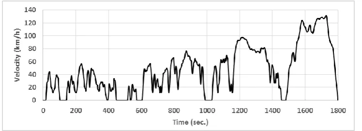
The performance of engine cooling system with adifferent controller is tested using the Worldwide Harmonized Light-Duty Testing Procedure, (WLTP) [13]. This is a chassis dynamometer test cycle for determining emissions and fuel consumption from light-duty vehicles, designed based on the in-use driving databases provided by Europe, India, Japan, Korea and theUSA, see Fig. 6.
Figure 6. Vehicle Speed during WLTP Cycle.
A sequence of engine operating conditions (torque and speed) which represent this cycle has been preliminarily identified by knowing the mechanical characteristics of the vehicle, and therefore used in the comprehensive modelling. The cycle is used by the assumptions of constant tire dimensions, rolling resistance, aerodynamic coefficient of the vehicle, transmission and gear ratio and vehicle mass. The mechanical power requested to run a WLTP cycle can be calculated according to the following equation18.
P= 𝐹𝑖𝑛+ 𝐹𝑎𝑖𝑟𝑜+ 𝐹𝑅𝑜𝑙 𝑉 (18) P = (m a + m g𝐶1 + 1 2 ρ 𝐶𝑥𝑆𝑓𝑟𝑜𝑛𝑡𝑉2) 𝑉 (19)
For the proper set of data, the test cycle vehicle speed in Fig. 6 is converted to equivalent power on the vehicle wheels using Eq. 20 with total running time 1800 second.
Fig.7 shows the mechanical power requested to run the WLTP cycle. The highest propulsive power is around 301–35 kW, while the mean propulsive power is about 7 kW and during the vehicle deceleration the requested power is equal to zero and this means that the engine is unloaded.
Figure7: Wheel Power during WLPT Cycle.
So, once engine load and speed changing during time are specified as shown in the model calculates all the quantities related to the engine thermal states, cooling circuits,and component behaviour.
Figure 8. Engine cooling temperature using LQR and PID control compared to theconventional cooling system during WPLT test cycle.
As the engine warms up, the coolant temperature at the engine outlet increases to the operation temperature 370 K. It can be seen that the temperatures of the two electrically controlled system are higher than the conventional cooling system due to the highset points which have been defined while the warm-up time until the engine coolant temperature reaches steady state is reduced by using PID and LQR controller by around 33%. These results indicate the insignificance of the mechanical thermostat for the electrically cooled system.Also, the electrically controlled system created thermal stabilization for the engine cooling temperature at a steady state due to high dynamic response but the conventional system presents temperature oscillations around a value of (358-364 K) which indicates the inability to stabilize the temperature during the test cycle.
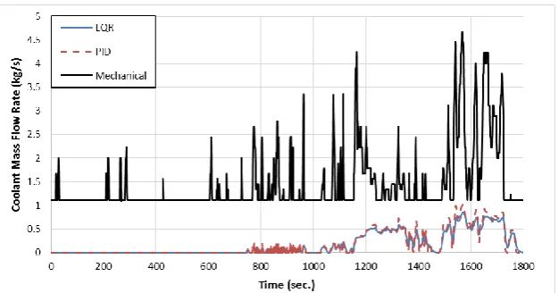
Fig. 9 presents the coolant flow rate for the mechanical water pump during the test cycle. Due to the direct connection between the mechanical water pump and engine crankshaft, the pump is continuously working during the test related to the engine speed without any control and with high flow rate due to high speed but using an electric cooling pump with electrical control for both LQR or PID controllers.
Figure 9. Coolant mass flow rate using LQR and PID controller in compared to theconventional cooling system during WPLT test cycle.
Figure 10. Electric water pumps power consumption by using LQR and PID control compared to mechanical water pump power consumption during WPLT test cycle.
Fig.11 shows the electric cooling fan air mass flow rate in the conventional cooling system during test cycle which working as ON/OFF control with values varied between zero and 0.9 kg/s depend on engine coolant temperature and it starts to work at 365 K, stop working after temperature decrease by around 10 degrees.
Figure 11. Cooling fan flow rate in conventional system Figure 12. Cooling fan air flow rate with LQR
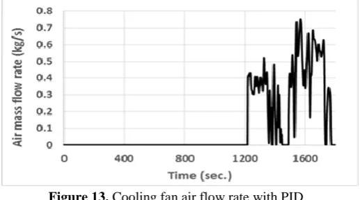
Figure 13. Cooling fan air flow rate with PID
Fig. 12 and 13 show the electric cooling fan air mass flow rate with LQR and PID controllers during the test cycle. The average air mass flow rate for both LQR and PID controller is around 0.5 kg/s which decrease by 44% compared to a conventional cooling system, this directly effects on electric power consumed by the cooling fan.
The generated heat during the combustion process converted to brake power, exhaust gas enthalpy and to the engine cooling. The heat removed by the coolant is directly affectedby the engine fuel consumption [14].
By using mathematical model the fuel consumed by the engine during test cycle for three systems has estimated based on energy expenditure from theengine during test cycle which divided into four parts:
1. The energy required for overcoming the road resistance. 2. Energy expended at idle mode.
3. The energy required for movement with acceleration. 4. The energy required for movement with deceleration. The equation for fuel consumption takes the form [15]:
𝑄 = 𝐸𝑇 /𝐻𝐿 (20)
Where (𝐻𝐿) is the calorific value of one liter of fuel and (𝐸𝑇) is the total energy consumed during the testcycle.
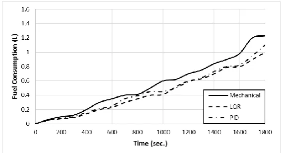
Fig. 14 show the fuel consumption during thetest cycle and it is clear that the fuel consumption reduced by around 20% by using theelectrically controlled cooling system with both LQR and PID techniques compared to the conventional cooling system.
Figure 14. Engine fuel consumption during WLPT cycle for the three systems.
V.
CONCLUSION
In this work, a proposed controller for the cooling system of the internal combustion engine is introduced and simulated to control the engine temperature. The controller is designed based either on Proportional Integral Derivative (PID) or Linear Quadratic Regulation (LQR) control techniques. The Worldwide Harmonized Light Vehicles Test Cycle (WLTC) is used to test the proposed controller using MATLAB/SIMULINK software. The results showed that the proposed controllers are highly controlled the engine cooling temperature at the desired operating value of 370 K on different operating conditions according to WLTC test cycle. Also, the average operating durations for the water pump and radiator air fan are reduced by 88% and 44% respectively. This will lead to optimizing the vehicle performance with minimum power consumption which ultimately affects fuel economy with increasing the operating life for the engine cooling management parts.
The results of the conventional cooling system showed delays in reaching the steady state condition, imperfect control of the engine thermal status compared to the systems working with the electrical pump. The use of electrically controlled cooling system the fuel consumption by about 20%.
REFERENCES
[1] C.Brace, H.Burnham-Slipper, R. Wijetunge, N. Vaughan, K. WrightandD. Blight, Integrated Cooling Systems for Passenger Vehicles. SAE technical paper No. 2001-01-1248.
[2] J.Wagner, V.Srinivasan, D. Dawson, andE. Marotta, Smart Thermostat and Coolant Pump Control for Engine Thermal Management Systems. Soc. Automotive. Eng., SAE paper 2003-01-0272.
[3] F. Lodi, Reducing cold start fuel consumption through improved thermal management. TheUniversity of Melbourne 2008.
[4] H. Cho, D.Jung,Z. Filipi,andD. Assanis, Application of Controllable Electric Coolant Pump for Fuel Economy and Cooling Performance Improvement. Proceedings of the ASME IMECE, Advanced Energy Systems Division, vol. 44, pp. 43-50, Anaheim, CA 2004.
[5] Jr. Chalgren, andD. Allen, Light Duty Diesel Advanced Thermal Management. SAE paper No. 2005-01-2020.
Design, Component Testing,and Block Redesign, SAE paper no. 2006- 01-1232.
[7] P. Setlur, J. Wagner, D. Dawson, and E. Marotta, An Advanced Engine Thermal Management System:Nonlinear Control and Test. IEEE/ASME Transactions on Mechatronics, vol.10, no.2, pp.210-220,2005.
[8] R.Cipollone, and C. Villante, Vehicle Thermal Management: A Model-Based Approach.Proceedings of the ASME Internal Combustion Engine Division, pp. 85-95, Long Beach, CA 2011.
[9] M. Salah, T. Mitchel, J. Wagner and D.Dawson, Adaptive and Robust Control for Thermal Management Systems,Automotive Research Laboratory Departments of Mechanical and Electrical Engineering Clemson University, Clemson, SC 29634-0921, 2013.
[10] T. Mitchell, M.Salah, J. Wagner and D. Dawson, Automotive Thermostat Valve Configurations: Enhanced Warm-Up Performance. Journal of Dynamic Systems, Measurement,and Control, Vol. 131 / 044501-7, 2009.
[11] C. Hoon, J.Dohoy, S. an and N. Dennis (2004). Application of Controllable Electric Coolant Pump for Fuel Economy andCooling Performance Improvement,ASME International Mechanical Engineering Congress, 2004.
[12] Wu. Yuh, Bo. Chiuanand H. Chi, Heat transfer for small-scale air cooled spark ignition four-stroke engines. Heat and Mass Transfer. International Journal of Heat and Mass Transfer 49 3895–3905, 2006.
[13] A. Marco and A. Alberto, Design and analysis of a cooling control system of a diesel engine to reduce emissions and fuel consumption. ABCM Symposium Series in Mechatronics - Vol. 5- Section II – Control Systems, 39-48, 2012.
[14] H. Salah, H. Mitchell, R. WagnerandM. Dawson, A Smart Multiple-Loop Automotive Cooling System Model Control and Experimental Study. IEEE/ASME Transactions on Mechatronics, 2009.
[15] B. Michael and S. Efraim, A Model for Vehicle Fuel Consumption Estimation at Urban Operating Conditions. INTERNATIONAL JOURNAL OF MECHANICS Issue 1, Volume 7, 2013.