Simulation for the Microstructure and Rheology
in Bidisperse Magnetorheological Fluids
Haitao Li
College of Resources and Environmental Science, Chongqing University, Chongqing, China Email: [email protected]
Xianghe Peng
College of Resources and Environmental Science, Chongqing University, Chongqing, China Email: [email protected]
Abstract—There are many ferromagnetic particles dispersed in carrier oil in magnetorheological fluids. Assuming Newtonian motion, the forces between particles of different radius, including magnetic interaction, viscous force and contact interaction, are obtained, and the corresponding model for motion of particles is proposed. Under an external magnetic field, the microstructures in bidisperse magnetorheological fluids are simulated, and the mechanical properties under both external magnetic field and macroscopic shear strain are investigated. The influence of attached particles on the side of dipolar chains is analyzed. It shows that particle size ratio in bidisperse suspensions can influence the performance of MR fluids.
Index Terms—magnetorheological fluids, microstructure, bidisperse suspensions
I. INTRODUCTION
Magnetorheological (MR) fluids consist of ferromagnetic particles (usually iron particles) dispersed in carrier oil. Under an applied magnetic field, the particles are magnetized to dipoles and form chains aligning in the direction of applied field, which makes MR fluid change from a liquid state to a solid-like state and results in a remarkable change in its rheological properties, especially the appearance of distinct yield shear stress. Such peculiar character makes MR fluids be widely used for the purpose of active or semi-active control, such as shock absorber, braking device, damper, hydraulic system, and so on[1-3].
The properties of MR fluid depend strongly on physical and geometrical aspects of its components, of which the size of particle plays an important role. In experimental investigation, it was found that both the apparent viscosity and Bingham yield stress increases with the increase of particle size if particles are uniform [4]. It was also showed that yield stress depends on particle size if the particle is small (about 0.5~1μm), but
such dependence vanishes for very large particles (with radius of between 25 and 45 μm) [5]. Since the particle size can influence the performance of MR fluids in some cases, MR fluids may have a dependence on particle size distribution. Weiss claimed that the use of mixed particles of different size could increase the MR effect [6]. Foister observed a larger yield shear stress in bidisperse suspensions [7]. Zhang found that optimizing size distribution will induce a reduction on the apparent viscosity of MR fluids [8]. Dodbiba pointed out that the MR fluid with 60% fraction of large particles exhibited the highest MR response [9]. Wereley investigated the MR fluid mixture composed of conventional micron-sized particles and nanometer-micron-sized particles, and found that replacing 20% of the microparticles with nanoparticles lead to an increase in the dynamic yield stress of over 15% at high magnetic field [10].
Besides experimental investigations, some theoretical models were proposed to study the influence of particle size distribution on the properties of electrorheological (ER) fluids. Ota et al studied the ER fluid consisting of particles of two different sizes with a cubic chain model and concluded that ER fluids with uniform particles possesses a larger static yield stress [11]. Wang et al investigated the influence of the standard deviation of the size distribution on the viscous property of an ER fluid and found that monodisperse particles could result in better properties [12]. The above mentioned researches, however, used ideal models and can hardly give the exact response of MR or ER fluids, because the microstructures in MR or ER fluids with mixed particles of different size are complicated.
It has been found that MR effect is caused by the change of microstructures. Particles disperse randomly in liquid before a magnetic field is applied. When subjected to a magnetic field, the particles aggregate and form chains of dipoles aligned in the direction of the applied field [13]. This phenomenon implies that MR fluids with different components will have different microstructures, and the properties of MR fluids strongly depend on their microstructures [14]. So an appropriate way to analyze the mechanical properties of MR fluids is the simulation method. The microstructures of MR fluids with mixed
Project supported by the National Natural Science Foundation of China (10872220, 11002165) and the Fundamental Research Funds for the Central Universities (CDJZR10240010).
particles of different size can be obtained in the simulation and the corresponding mechanical behaviors can be derived synchronously. Kittipoomwong employed particle-level simulations to investigate the rheological properties of bidisperse MR fluids, and found that the dynamic yield stress of bidisperse suspensions is larger than that of monodisperse suspensions at the same particle volume fraction [15].
In this paper, a micro-to-macro approach is developed for the investigation of the behavior of MR fluids. Three kinds of forces, including magnetic force, repelling force and viscous force, on each particle in MR fluid subjected to a parallel static magnetic field are introduced. The motion of each particle is derived with the second Newtonian law and the process of chain formation is analyzed with the viewpoint of micro-mechanics. The corresponding computer program is developed, making use of some concepts of molecular dynamics and discrete element methods, and the microstructures of MR fluid with different particle sizes under different external conditions are simulated. The rheological properties with different particle size ratio are obtained.
II. EQUATION OF MOTION
For simplicity, the particles are assumed to be spherical. In a constant statically magnetic field, the particle i in magnetic field will be magnetized as a dipole with the moment [16]
H M
m π 3β
3 4 3
i i
i =V = a , (1)
where ai and Vi are respectively the radius and volume
of particle i, H and M are intensity of applied magnetic
field and intensity of magnetization,
) 2 ( ) 1 ( − + = μ μ
β , μ is the relative permeability of the
particles.
It should be noted that the magnetic field is not homogeneous over the whole suspension due to the disturbance of local magnetic dipoles. The magnetic field in suspension should be the summation of local magnetic fields induced by all neighboring dipoles and applied magnetic field. The magnetic moment mi on particle i
can, therefore, be expressed as [14]
⎥ ⎥ ⎦ ⎤ ⎢ ⎢ ⎣ ⎡ ⎟ ⎟ ⎠ ⎞ ⎜ ⎜ ⎝ ⎛ − + =
∑
≠i j ij j ij ij ji i i r r m V 3 0 4 0 4 4 3 3 πμ πμβ H r m
m
, (2)
whereμ0is the vacuum permeability, rij is the vector
describing the relative position from dipolar particle j to dipolar particle i, and rij=║rij║. mir and mjr denote
respectively the projections of magnetic moments mi and mj on rij.
The point-dipole approximation is used for the computation of magnetic force between particles. The magnetic force on particle i should be summation of the interaction from all other particle dipoles and is expressed as (see the appendix)
∑
≠ ⎥ ⎥ ⎥ ⎥ ⎦ ⎤ ⎢ ⎢ ⎢ ⎢ ⎣ ⎡ + + − ⋅ = i j i jr j ir ij ij jr ir j i ij m i m m r m m r ) ( 4 3 ) 5 ( 4 3 4 0 5 0 m m r m m F πμ π μ . (3)Assuming that particles are stiff, the repelling force occurs on the ith particle as it contacts the other particles or the wall of container. A simple model for such kind of force can be expressed as [17]
ij ij i
j i j
ij r i r a a r F r F
∑
≠ ⎥ ⎥ ⎦ ⎤ ⎢ ⎢ ⎣ ⎡ ⎟ ⎟ ⎠ ⎞ ⎜ ⎜ ⎝ ⎛ − + −= 0exp α 1 , (4)
where α is a material constant. The parameter F0 is
chosen in order to balance the magnetic force and repelling force when two dipolar particles align in the direction of magnetic field and contact each other. In this case, the distance between two particles rij=ai+aj, and F0
can be derived as
4 3 3 2 0 4 0
0 3( )
8 ) ( 2 3 j i j i j i j i a a a a M a a m m F + = + = πμ π
μ . (5)
Neglecting the flow instability that may occur at a sufficiently high velocity, and considering a slow motion of particles in liquid, the viscous resistance can approximately be described with Stokes’ drag as
⎟ ⎠ ⎞ ⎜ ⎝ ⎛ − − = f i i v i dt d
a u v
F 6π η , (6)
where η is the coefficient of viscosity of fluid, dui /dt is the velocity of particle i, and vf is the velocity of liquid
at the position of particle i.
The Brownian motion of particles in the range of temperature concerned is neglected because the corresponding thermal energy is much smaller than magnetic and mechanical energies, so that it should have a negligible effect on the evolution of particle structure [13]. The motion of particle i, therefore, can be described with the second Newtonian law of motion as
v i r i m i i i dt d
m u2 =F +F +F 2
,
(7)where mi=ρVi is the mass of particle i, and ρ is the
density.
III. MECHANICAL BEHAVIOR OF MRFLUID WITH MIXED
PARTICLES OF DIFFERENT SIZE
In the initial state, N particles distribute randomly in the 3D simulation region with dimensions (Lx, Ly, Lz)=(60μm, 60μm, 100μm). After applying magnetic
1.2 1.7 2.2
0 0.2 0.4 0.6 0.8 1 1.2
Size ratio of fine particles to coarse particles
Y
ie
ld
sh
ea
r st
re
ss /
k
Pa
Figure 1. Yield shear stress vs. particle size ratio.
[18] is used in this work. The repeated loop of Velocity-Verlet integrator is stated as follows:
(i) The initial positions of particles
{
uit=0 =uˆi}
(i=1,2,…,N). (8)
(ii) The initial velocities of particles
{
vit=0 =0}
(i=1,2,…,N). (9)
(iii) The accelerations of the particles
m t t i i
) ( )
( f
a =
(i=1,2,…,N), (10)
where ( ) m( ) r( ) v( )
i t = i t + i t + i t
f F F F is the resultant force on
the ith particle, which can be derived with the position and velocity of the ith particles at instant t. Assuming that the computation up to instant t has been finished, given an increment of time Δt, the new position and velocity can be derived as following.
(iv) The position of the ith particle at t+Δt
2
) ( 2 1 ) ( ) ( )
(t t i t i t t i t t
i Δ u v Δ a Δ
u + = + + . (11)
(v) The velocity of the ith particle at t+Δt
[
t t t]
t tt
t i i i
i Δ 2 () ( Δ)Δ
1 ) ( )
( + =v + a +a +
v . (12)
(vi) Reallocate the particles according to their new positions and update the Verlet list of particles.
(vii) Return to (iii) and repeat the loop from (iii) to (vi) until a steady state is achieved. Similar with the molecular dynamics, the total inter-particle potential is employed to estimate the steady state in the simulation. During the simulation, the inter-particle potential, including dipolar potential and repulsive potential, decreases sharply at first and then tends to be a constant. If the decrement of potential in two continuous time steps is less than the value user defined, a steady state is achieved.
Assuming the magnetic field is in z direction and MR fluid is located between two sufficiently large parallel plates. The bottom plate of simulation domain is fixed and the top plate can move in x direction. In order to consider the interaction between plates and particles, some particles are assumed to be attached on the surface of plates. The interaction between plates and particles can, therefore, be approximately considered as the interaction between particles. Considering the domain used in the simulation is just a part of whole region, periodicity boundary condition is adopted.
It should be noted that a complete simulation is time consuming, especially in the computation of magnetic force between dipolar particles, because the computation of the force on each particle is related to the interaction between the particle and all other particles. Therefore the link-cell method, which is of O(N) time complexity and was developed in molecular dynamics simulation, is used in the developed approach. In order to further improve
the efficiency of computation, Verlet list method is adopted in addition to link-cell method.
The numerical simulation for shear process under external magnetic field is divided into two steps. The first step is to obtain a static chain-like structure in the absence of flow. Following this a shear flow is applied to get the shear stress of MR fluids. In the simulation, the overall volume fraction of iron particles and the volume fraction of coarse particles to overall particles, which are respectively 17% and 80%, are kept constant. The size of coarse particles, whose radius is 5 μm, is also constant, while the radiuses of fine ones are 4μm, 3μm, 2μm, 1μm, respectively. The density of particles is 7.6×10³ kg /m3, the viscosity of oil carrier is 0.01 N•s/m2 and the intensity
of magnetic field is 35 kA/m. The yield shear stress with different particle size ratio is shown in Fig. 1. It should be pointed out that the results are average values using several different initial configurations.
It is found from Fig. 1 that the yield shear stress decreases with the increase of particle size ratio of fine particles to coarse ones meanwhile overall volume fraction is constant. It also shows that mixing coarse particles with some fine particles can increase the yield shear stress. This implies that MR fluids can have higher stress due to optimizing the mixing ratio.
IV. MICROSTRUCTURE OF MRFLUIDS WITH MIXED
PARTICLES OF DIFFERENT SIZE
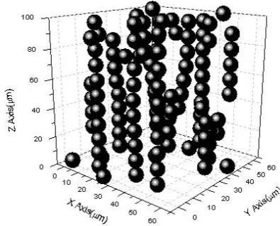
The microstructure of MR fluids under applied magnetic field is shown in Fig. 2. The particles are uniform and with same radius. It can be seen that a chainlike microstructure is formed.
0 0.05 0.1 0.15
2 4 6 8
a/ μm
[
a
/(2
a
+
d
)]
3
d=0.5mm d=1mm1μm
0.5μm
Figure 5. The variation of a3/(2a+d)3 against a.
Figure 2. Microstructure of MR fluids with uniform particles under an external magnetic field.
Figure 3. The representative slot for simulation in 2D systems.
(a)
0 30 60 90
0 100 200 300 400 500 600
μm
μ
m
0 30 60 90
0 100 200 300 400 500 600
μm
μ
m
(b)
(c) 0
30 60 90
0 100 200 300 400 500 600
μm
μ
m
Figure 4. Simulation of microstructure of MR fluid with different size ratio. The coarse particles is 5μm in radius and the fine ones is
3μm in (b), 2μm in (c). The volume fraction of coarse particles to that of all particles is 80% in (b) and (c), while the overall volume
fraction of particle is 17% in the above three samples.
simulation region are 600μm, 90μm and 10 μm, respectively. The other parameters are same with above 3D systems.
Fig. 4 shows the simulated microstructures in MR fluid with different size ratio. It can be seen that bidisperse systems (Fig. 4(b) and (c)) would form more chains aligned in external magnetic field than monodisperse systems (Fig. 4(a)). That may be the cause why using mixed particles of different size could increase a larger yield shear stress than uniform particles. Comparing Fig. 4(b) with Fig. 4(c) it would be found that the radius of fine particles is smaller and the tendency to form more chains is greater. If the number of fine particles is much more than that of coarse ones, the chains will be mainly composed of fine particles. In this case, the microstructure is more complex, and many short chains merge together to form cluster or column structure.
Another phenomenon can be found in Fig. 4 that with the decrease in radius of fine particles, there is a tendency of the larger particles to form more chainlike aggregates aligned well in applied magnetic field. The formation of straight chains by the large particles is dependent on the ratio of particle sizes. This is similar with Kittipoomwong’s investigation [15]. Ekwebelam employed a contacting pair distribution function approach analysing the microstructure under static mode captures well the higher tendency of the formation of straight or close-to-aligned structures exhibited by the bidisperse systems over monodisperse systems [19].
It also can be analyzed from the following conclusion. If the overall volume fraction is constant and the particles are uniform in size, the MR fluids with larger particles would have larger yield shear stress, which may be attributed to several factors. A theoretical model for the analysis of the mechanical behavior has been proposed by Li et al [20], where it can be seen that the yield shear stress is proportional to a3/(2a+d)3, where a is particle radius and dis the clearance between particles. It can be deduced from Fig. 5 that the yield shear stress increases with the increase of particle size provided d keeps constant. So the microstructure with more coarse particles aligned well in magnetic field can have better mechanical property.
0 30 60 90
0 100 200 300μm 400 500 600
μ
m
0 30 60 90
0 100 200 300 400 500 600
μm
μ
m
0 30 60 90
0 100 200 300 400 500 600
μm
μ
m
0 30 60 90
0 100 200 300 400 500 600
μm
μ
m
0 30 60 90
0 100 200 300 400 500 600
μm
μ
m
Figure 6. Simulation of the microstructure in MR fluid when an external magnetic field and a shear strain are applied simultaneously.
a
b
c
Figure 7. Typical defects in chains are characterized as (a) satellites, (b) cruciforms, and (c) double cruciforms.
0 30 60 90
0 30 60 90
μm
μ
m
0 30 60 90
0 30 60 90
μm
μ
m
0 30 60 90
0 30 60 90
μm
μ
m
0 30 60 90
0 30 60 90
μm
μ
m
0 30 60 90
0 30 60 90
μm
μ
m
0 30 60 90
0 30 60 90
μm
μ
m
(a) (b)
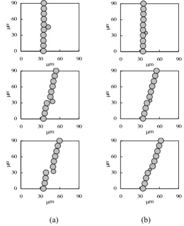
Figure 8. Simulation for the shear process of dipolar chains with satellite defects. The radius of coarse particles is 5μm while the
attached fine ones in (a) is 4μm, in (b) is 2μm.
new chains. It can be imagined that if the velocity of rupture and formation of chains is approximately equal to each other, i.e., an evolutional balance in the number of the available chains is achieved. In this process, the macroscopic shear stress of MR fluid will increase gradually and tend to a steady state corresponding to the governing magnetic and mechanical parameters.
V. INFLUENCE OF ATTACHED PARTICLES
It should be noted that not all the particles align end to end to form simple chains along the applied magnetic field. It can be seen in Fig. 4 and Fig.6 that there is a kind of chain defects caused by additional attached particles, of which three typical examples are shown in Fig.7. During shear deformation, the satellite particles can influence significantly the behavior of chains.
If the ratio of coarse particles is larger, the microstructure is mainly composed by simple chains and the chains are mainly composed of coarse particles, in
this case some fine particles would attached on the side of chains. Fig. 8 shows the shear process the chains with satellite defects, where the bottom of chains is fixed and the top is translated perpendicular to the magnetic field. It can be seen that both chains incline and stretch gradually during the shear deformation, but the reason of rupture in each dipolar chain is different due to the size of fine particles. When the chain is stretched, some space may occur to the chain. In Fig. 8(a) the attached particle could not be pulled into the space of chain. It would attach to the end of one segment and lead to breaking of the chain. However, the effect of fine particle in Fig. 8(b) is mainly to remedy the space in the chain. During the shear deformation the attached particle could be pulled into the chain to remedy the “lost” link.
The corresponding mechanical properties of dipolar chains in the shear deformation process are shown in Fig. 9, where the radius of coarse particles is 5μm and the attached ones are 4μm, 3μm and 2μm, respectively. During the shear process, dipolar chain would incline so the shear strain can be determined approximately by the obliquity of the chain, and the corresponding shear force is obtained from the interaction among dipoles. It can be seen that the shear force increases with the decrease of radius of attached particles, and the critical shear strain where stress reaches maximum also increases under the same condition. This may be caused by the different deformation process of dipolar chains shown in Fig. 8. Considering the shear stress of MR fluid is the summation of shear force of chains occupying a unit area, the relationship of yield shear stress versus particle size ratio in Fig. 1 can be partly explained.
0 2 4 6 8 10 12 14 16 18 20
0 0.1 0.2 0.3 0.4
Shear strain Sear fo rce 1 0
6 / N
Radius of attached particle is 4 mm Radius of attached particle is 3 mm Radius of attached particle is 2 mm μm μm μm
×
Figure 9. Shear force of dipolar chains with attached particles of different size.
θ r2
r r1 − m Q + m Q nˆ a P
Figure 10. Schematic illustration of magnetic dipole.
high, the dipolar interaction between attached particle and the chain is weaker than the viscous drag, the chain will rupture directly at the weak point and the rearrangement will not occur.
VI. CONCLUSION
The microstructures and mechanical behaviors of MR fluids with different size ratio are analyzed based on a platform of numerical simulation. Using Newtonian law, the motion of particles is determined by the magnetic interaction, viscous force and contact interaction. A model is developed to simulate the formation of dipolar chains of MR fluids containing ferromagnetic particles with different particle sizes under an external magnetic field. The dynamic microstructure of MR fluid flowing perpendicularly to the magnetic field direction is also simulated. The yield shear stress at different size ratio is obtained. It is found that particle size ratio in bidisperse suspensions can influence the shear stress. That implies optimizing particle size distribution can get a higher stress and improve the rheological properties of MR fluids.
APPENDIX MAGNETIC FORCE BETWEEN DIPOLES
A. Magnetic Field Induced by Dipole Each dipole has two magnetic poles +
m
Q and Qm−. The
magnetic field H induced by one magnetic pole, based on
Coulomb's law, can be expressed as
r H ˆ 4 1 2 0 r Qm πμ
= , (13)
where rˆ is the unit vector of r.
Then the magnetic field in location P induced by one dipole can be derived as
⎟⎟ ⎠ ⎞ ⎜⎜ ⎝ ⎛ − = 2 2 2 2 1 1 0 ˆ ˆ
4 r r
Qm r r H
πμ , (14)
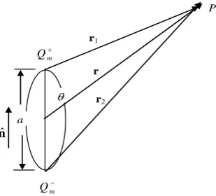
where r1 and r2 are vectors of every pole to P, as shown
in Fig. 10, and can be described as following,
a r r a r r 2 1 2 1 2 1 + = − = or ⎟ ⎠ ⎞ ⎜ ⎝ ⎛ + = ⎟ ⎠ ⎞ ⎜ ⎝ ⎛ − = n r r n r r ˆ 2 ˆ ˆ ˆ 2 ˆ ˆ 2 2 1 1 r a r r r a r r . (15) If a << r1 and a << r2, then
θ θ cos 2 cos 2 2 1 a r r a r r + ≈ − ≈ . (16)
So the following can be derived,
⎟ ⎠ ⎞ ⎜ ⎝ ⎛ − ≈ ⎟ ⎠ ⎞ ⎜ ⎝ ⎛ + ≈ θ θ cos 1 1 1 cos 1 1 1 2 2 2 2 2 1 r a r r r a r r , ⎟ ⎠ ⎞ ⎜ ⎝ ⎛ + ⎟ ⎠ ⎞ ⎜ ⎝ ⎛ − ≈ ⎟ ⎠ ⎞ ⎜ ⎝ ⎛ − ⎟ ⎠ ⎞ ⎜ ⎝ ⎛ + ≈ n r r n r r ˆ 2 ˆ cos 2 1 ˆ ˆ 2 ˆ cos 2 1 ˆ 2 1 r a r a r a r a θ θ . (17)
The following equation can be obtained from (15)~ (17),
(
r n)
[
r( )
r n n]
rr ˆ ˆ ˆ ˆ
3 ˆ cos ˆ 3 ˆ ˆ 3 3 2 2 2 2 1
1 − ≈ − = ⋅ −
r a r
a r
r θ .(18)
So magnetic field induced by one dipole can be rewritten as
( )
[
rr n n]
H 3ˆ ˆ ˆ ˆ
4 1 3 0 − ⋅ = r aQm
πμ . (19)
B. Magnetic Potential between Two Dipoles The magnetic potential m
W of one dipole located in magnetic field H can be described as [21]
H m⋅
−
= μ0
m
W . (20)
(
)(
)
[
]
(
)
ir jr ij j i ij j i ij j ij i m ij m m r r r W 3 0 3 0 3 0 4 3 4 ˆ ˆ 3 4 π μ π μ π μ − ⋅ = ⋅ − ⋅ ⋅ − = m m m m r m r m . (21)C. Magnetic Force between Dipoles
The force applied on a dipole which is located in magnetic field is expressed as
m m
W
∇ =
F . (22)
So the magnetic interaction applied on dipoles i can be derived from (21) and (22),
) ( 4 3 ) 5 ( 4 3 ˆ ) ˆ )( ( 4 3 ˆ ) )( ˆ ( 4 3 ˆ ) )( ( 4 15 ˆ ) ( 4 3 4 0 5 0 5 0 5 0 60 4 0 i jr j ir ij ij jr ir j i ij ij ij j ij i ij ij ij j ij i ij ij ij j ij i ij ij j i ij m i m m r m m r r r r r m m r m m r r m r m r r m r m r r m r m r m m F + + − ⋅ = ⋅ ⋅ + ⋅ ⋅ + ⋅ ⋅ − ⋅ = π μ π μ π μ π μ π μ π μ . (23)
The magnetic force applied on dipoles j is m j F = m
i
F
− . It
should be noted that the magnetic force can be divided into two terms. The first term on the RHS of (23) is along the vector describing the relative position from dipolar particle j to dipolar particle i, but the second term is usually not. The moment induced by two magnetic forces
m i
F and Fmj is equal to the magnetic moment of both
dipoles, but the total internal moment is zero.
If there are many dipoles in a system, the magnetic interaction would be complex because the force occurs between every two dipoles. In this condition, the magnetic force applied on dipole i is the total interaction from all the other dipoles and can be described as
∑
≠ ⎥ ⎥ ⎥ ⎥ ⎦ ⎤ ⎢ ⎢ ⎢ ⎢ ⎣ ⎡ + + − ⋅ = i j i jr j ir ij ij jr ir j i ij m i m m r m m r ) ( 4 3 ) 5 ( 4 3 4 0 5 0 m m r m m F π μπμ . (24)
ACKNOWLEDGMENT
The authors gratefully acknowledge the financial support to this work from the Natural Science Foundation of China under Grant Number 10872220, 11002165 and the Fundamental Research Funds for the Central Universities under Grant Number CDJZR10240010.
REFERENCES
[1] F. Goncalves, K. Koo, and M. Ahmadian, “A review of the
state of the art in magnetorheological fluid technologies -
Part I: MR fluid and MR fluid models,” Shock and
Vibration Digest, Vol. 38, pp. 203–219, 2006.
[2] C. Maranville, and J. Ginder, “Small-strain dynamic
mechanical behavior of magnetorheological fluids
entrained in foams,” International Journal of Applied
Electromagnetics and Mechanics, Vol. 22, pp. 25–38,
2005.
[3] S. Ye, and K. Williams, “Torsional vibration control with
an MR fluid brake,” Proceedings of SPIE – Damping and
Isolation, pp. 283–292, 2005.
[4] D.W. Felt, M. Hagenbuchle, J. Liu, and J. Richard,
“Rheology of a magnetorheological fluid,” Proceedings of
the 5th International Conference on electrorheological Fluids, Magnetorheological Suspensions and Associated Technology, pp. 738–746, 1995.
[5] E. Lemaire, A. Meunier, and G. Bossis, “Influence of the
particle-size on the rheology of magnetorheological
fluids,” Journal of Rheology, Vol. 39, pp. 1011–1020,
1995.
[6] K.D. Weiss, J.D. Carlson, and D.A. Nixon,
“Magneto-rheological fluid with no agglomeration or sedimentation|having a viscosity comparable with conventional magneto-rheological fluids while providing
greater yield strength and a reduction in fluid cost,” US
Patent 6027664, 2000.
[7] R.T. Foister, “Magneto-rheological fluid with no
agglomeration or sedimentation |comprising low coercivity, spherical magnetic particles dispersed in liquid medium, consisting of two groups of particles with
different diameters’” U.S. Patent No. 5667715, 1997.
[8] P. Zhang, Q. Liu, and Y. Huang, “Study on the rheology
character of magneto- rheological fluid,” Metallic
Functional Materials, Vol. 1, pp. 22–25, 2002.
[9] G. Dodbiba, H.S. Park, K. Okaya, and T. Fujita,
“Investigating magnetorheological properties of a mixture of two types of carbonyl iron powders suspended in an
ionic liquid,” J. Magn. Mater, Vol. 320, pp. 1322–1327,
2008.
[10]N.M. Wereley, A. Chaudhuri, and J.H. Yoo, “Bidisperse
magnetorheological fluids using Fe particles at nanometer
and micron scale,” Journal of Intelligent Material Systems
and Structures, Vol. 17, pp. 393–401, 2006.
[11]M. Ota, and T. Miyamoto, “Optimum particle-size
distribution of an electro- rheological fluid,” J. Appl. Phys.,
Vol. 76, pp. 5528–5532, 1994.
[12]Z. W. Wang, Z. F. Lin, and R. B. Tao, “Influence of the
size distribution of particles on the viscous property of an
electrorheological fluid,” Chin. Phys. Lett., Vol. 14, pp.
151–154, 1997.
[13]J. Popplewell, and R.E. Rosensweig, “Magnetorheological
fluid composites,” Journal of Physics D: Applied Physics,
Vol. 29, pp. 2297–2303, 1996.
[14]E.M. Furst, and A.P. Gast, “Micromechanics of
magnetorheological suspensions,” Physical Review E, Vol.
61, pp. 6732–6639, 2000.
[15]D. Kittipoomwong, and D.J. Klingenberg, “Dynamic yield
stress enhancement in bidisperse magnetorheological
fluids,” J. Rheol., Vol. 49, pp. 1521–1538, 2005.
[16]S. Melle, O.G. Calderón, G.G. Fuller, and M.A. Rubiob,
“Polarizable particle aggregation under rotating magnetic
fields using scattering dichroism,” Journal of Colloid and
Interface Science, Vol. 247, pp. 200–209, 2002.
[17]S. Melle, O.G. Calderón, M.A. Rubiob, and G.G. Fuller,
“Rotational dynamics in dipolar colloidal suspensions: video microscopy experiments and simulations results,”
Journal of Non-Newtonian Fluid Mechanics, Vol. 102 , pp.
135–148, 2002.
[18]Y. Wei, “Molecular-dynamics simulation study on the
irregular size effects of gold nanoclusters,” M.S.
[19]C. Ekwebelam, and H. See, “Microstructural investigations of the yielding behaviour of bidisperse magnetorheological
fluids,” Rheol Acta, Vol. 48, pp. 19–, 2009.
[20]H. Li, X. Peng, and W. Chen, “A yield shear-stress model
of magnetorheological Fluids,” Chinese Journal of
Chemical Physics, Vol. 18, pp. 505–509, 2005.
[21]D.C. Li, Theory and Application of Magnetic Fluid,