145103-6868-IJET-IJENS © June 2014 IJENS
I J E N S
Abstract— The concentration of this numerical investigation is focused to generate data for developing optimum profile of Supersonic nozzle irrespective of the altitude of operation. The investigation has been carried out for different altitudes when the combustion conditions including combustion temperature, combustion pressure, specific heat ratio and molecular weight remain unchanged. Considering the aerodynamic issues, method of characteristics is chosen for profile generation. During the application of method of characteristics, exit pressure to atmospheric pressure ratio is maintained unity. The coding has been done in the MATLAB interface with an aim to generate maximum thrust at the outlet of the optimized supersonic nozzle. Both Mach and pressure distribution for maximum thrust generation are within the domain of interest of this investigation.
Index Term— Supersonic Nozzle, maximum thrust,
optimization of Supersonic Nozzle
I. INTRODUCTION
THE true exhaust velocity of the exhaust gas discharged by the supersonic nozzle depends on the retarding force, which in turn is related to the length of the nozzle. Along the nozzle the pressure drops, and the exit pressure decreases if the nozzle is lengthened. To obtain maximum exhaust velocity, and hence thrust, the design of the exhaust nozzle is optimized so that the exit pressure is equal to the ambient pressure. In the other words, consider the force accelerating the exhaust gas, and the atmospheric retarding force; both of them are proportional to the magnitude of the surface integral of pressure over the area of the chamber and nozzle. If the nozzle is made longer, the extra area will increase the thrust, provided exhaust pressure is greater or equal to the ambient
1
Senior Lecturer, Mechanical Engineering Program, School of Engineering and Information Technology, University Malaysia Sabah, Kota Kinabalu,
88400 Sabah, Malaysia, Phone: +60146594093, Email: [email protected]
2Lecturer, Department of Mechanical Engineering, Khulna University of
Engineering and Technology (KUET)., Khulna-9203, Bangladesh
Phone 88041769471 Ext. 433, Email: [email protected]
3Professor, Department of Mechanical Engineering, Khulna University of
Engineering and Technology (KUET)., Khulna-9203, Bangladesh
Phone 88041769471 Ext. 405, Email: [email protected]
retarding pressure. Again, this added area is not conducive for the aerodynamic optimization and, certainly, increases the weight of structure.
It is not abstruse to anyone that the pressure changes with the altitude. Therefore, if the nozzle possesses the correct length for sea-level pressure, then at altitude the exit pressure will be greater than ambient, and more thrust could have been generated if the nozzle had been made longer, and vice versa. For the vacuum, the nozzle should be of infinite length so that exit pressure becomes null at the outlet.
A number of investigations have been carried out to simulate the performance of supersonic nozzle. Different coding platform has been used successfully to develop JANNAF like codes. In this investigation, MATLAB has been utilized to investigate Mach and Pressure distribution along the nozzle for different altitude.
In practice, adding length to nozzle adds mass to the rocket, and after a certain point there is no further benefit from additional length, because extra thrust has less effect on the acceleration than does the extra mass. Therefore, in this investigation, the nozzle with minimum length, obtained utilizing Method of Characteristics, is subjected to produce maximum thrust at different altitudes.
II. THEORY
A. Method of Characteristics
Consider a two-dimensional, steady, inviscid, supersonic, irrotational flow in xy space. The flow variables such as velocity, pressure, temperature, etc are continuous throughout the xy space. There are points in which the derivatives of the
flow field variables are indeterminate. The lines joining these points are called Characteristics line. Along this line the flow variables may even be discontinuous. The exact governing
Mach and Pressure Distribution at the Exit
of the Nozzle: A Numerical Documentation
equation for such a flow is: * ( ) ( ) + ( )+
* ( ) ( ) + ( ) ( ) ( ) ( ) ( )=0 which is called velocity potential equation.
Since and * ( )+ ( )+* ( )+ ( ) ( ) ( )=0
The velocity potential and its derivatives are functions of x and y. Hence, for an exact differential,
It can be written as,
( ) ( )
Applying crammer rule to solve for
,
= ( ) ( ) ( ) ( )
= ………….(2)
When
,
is not defined. The situation will occur
for a specific direction ds away from point A and has a
specified value at point A. The only consistent result will be associated with D=0 is that N=0.
When
=
;
we say
is an indeterminate
form, which is allowed to be a finite value. Since
,
this implies that the derivatives of the flowvariables are indeterminate along these lines. That means Characteristics lines are found.
Again, expanding the denominator, ( ( )) ( ) + (
) + ( (
)) ( ) =0
( ( )) ( ) + ( ) + ( ( )) ( ) =0
Where,
is the slope of characteristic line. Solvingfor
by means of the quadratic formula,
= ( ) √( ) ( ( ))( ( )) ( ( )) = ( ) √( ) ( ( )) ………(3)
For and
=
( ) √( )( )
( ( ) )
If the local Mach angle μ is given by μ = ( ) and
= ( ) √( )( ) ( ( ) ) = ( ) √( ) ( )
After relevant algebraic and trigonometric manipulation, the preceding equation reduces to,
= tan ( )
The above equation describes the direction of the two characteristic lines that run through point A. It is apparent that the Characteristic lines are the Mach lines. The left and right running Characteristic lines are denoted as C+ and C-
It is notable that Characteristic lines are curved in space due to the fact that the local Mach angle depends on the local Mach number M(x, y) and the local streamline direction varies throughout the flow.
Now beyond any doubt, it is true enough to mention that these Characteristic lines are of no use apart from the fact that the governing partial differential equations which describes the flow reduces to ordinary differential equations along the Characteristic lines. These equations are named as compatibility equations.
Compatibility equations can be found by expanding the numerator from the equation (2),
( ( )) + ( (
)) = 0
= ( ( )) ( ( ))
Recalling the equation (3),
= ( ( )) ( ( ))( ( ) √( ) ( ( )) )
Since , and
145103-6868-IJET-IJENS © June 2014 IJENS
I J E N S = √ ( )
These compatibility equations can be integrated to obtain the results in terms of Prandtl-Meyer function,
These equations are known as Algebraic equations.
III. GRID GENERATION
A. Internal Point
Consider the internal grid point 1, 2 and 3, as shown in (figure 03). It is assumed that the location and flow properties at point 1 and 2 are known, whereas point 3 is the intersection of the C- characteristic through point 1 and C+ characteristic
through point 2.
1 + 1 = k - 1 = k – 3 Similarly, at point 2, k +2 = k +3= 2 – 2
From equation (4), for the point 3, it can be written,
3 + 3 = k - 3
3 – 3 = k + 3
From the above two algebraic equations, both 3 and 3 can be determined. The slope of the characteristic line joining
points 1 and 3 is assumed to be ( 1 + 3) - ( 1+ 3).
Similarly for characteristic line joining points 2 and 3, the
slope is ( 2 + 3) + ( 2+ 3).
B. Wall Point
Assume that we know the location and the properties at point 4. C- characteristic through point 4 intersects the wall at point 5. At point 5, the slope of the wall θ5 is known. The wall properties at the wall point 5 can be obtained from the known properties.
k -4 = k -5 = 4 + 4 Again, k -5 = 5 + 5
The characteristic line is assumed to be straight-line between points 4 and 5 with an average slope ( 4 + 5) -
( 4+ 5).
IV. RESULTS &DISCUSSION
A. Nozzle Configuration
Method of Characteristics (MOC) is a computational procedure used to compute and simulate the two-dimensional nozzles. Both the conventional (conventional Bell) and unconventional (Aerospike and Expansion-deflection) nozzles can be the subject of consideration of the MOC. In this investigation, it is axisymmetric rectangular supersonic nozzle being considered for its application at different altitudes.
B. Thrust Generation
Thrust generation is a function of nozzle exit area and nozzle length. One of the major interests of this investigation was to investigate the variation of the relation in between thrust and (Ae/A*).
For certain combustion pressure, combustion temperature, specific heat ratio and gas molecular weight, it is observed, thrust generation varies in different pattern at different altitudes. Thrust generation for altitude of 0-30,000ft varies at moderately similar pattern with change of Ae/A*, whereas thrust generation pattern starts to vary from approximately 50,000ft. From approximately 1,50,000ft, for Ae/A* of 40 (approx.), thrust generation becomes almost constant, i.e. atmospheric pressure change leaves no more impact on thrust generation if we can keep the ambient temperature unchanged. For the preceding and all following results of investigations, combustion temperature is 2,000K, combustion chamber pressure is 1,200,000Pa, specific heat ratio is 1.25 and molecular weight of gas is 25.4 kg/kmol.
C. Number of Characteristics Line
With grid refinement, like all other grid generation method, method of charateristics is observed to render better result. Nevertheless, the profile generated here is for 300 characteristics line. This code produces almost similar profile for 200-500 number of characteristics line. The reason behind chosing profiles with 300 characteristics line is avoiding the possiblities of grid becoming incontinuous for higher number of characteristics line.
Fig. 4. Maximum thrust for different altitudes
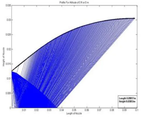
Fig. 5. Profile at 0ft or 0m
145103-6868-IJET-IJENS © June 2014 IJENS
I J E N S The profile of the rectangular supersonic nozzle changes
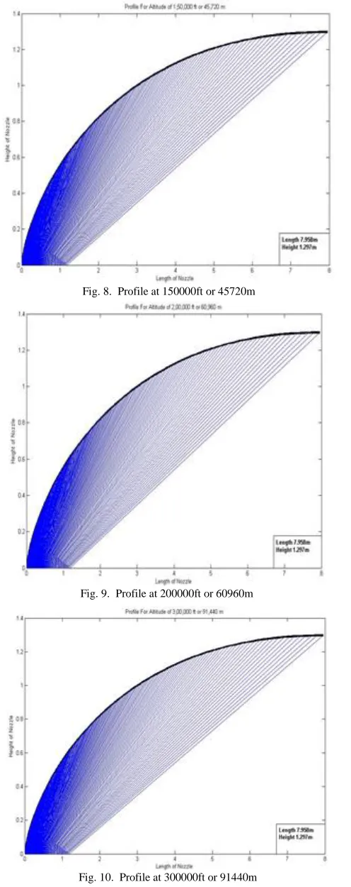
with the change of atmospheric pressure. The length of supersonic nozzle increases while the height does the same with the decrease of the pressure. The length of the nozzle, in figure 5-7, increases from 0.09817-0.6414m for the altitude of
0-50,000ft. From the altitude of approximately 1,50,000ft, in figure8-10, the length remains unchanged. The height of the nozzle, in figure 5-7, increases from 0.03053-0.1449m for the altitude of 0-50,000ft. The height of supersonic nozzle, in figure 8-10, remains same for the altitude of approximately 1,50,000ft and higher. To correspond with thrust calculation, it is inferrable that with the thrust generation becoming fixed at 1,50,000ft; the profile for the supersonic nozzle becomes fixed as well.
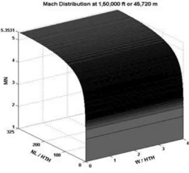
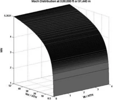
D. Mach Distribution
Mach distribution along the profile discussed above is represented below. These Mach distributions stand for the maximum thrust generation. Both Mach distributions curve along the nozzle height and length are presented.
Fig. 8. Profile at 150000ft or 45720m
Fig. 9. Profile at 200000ft or 60960m
Fig. 10. Profile at 300000ft or 91440m
Fig. 11. Mach Distribution along nozzle height at 0ft
Fig. 13. Mach Distribution along nozzle height at 10000ft
Fig. 14. Mach Distribution along nozzle length at 10000ft
Fig. 15. Mach Distribution along nozzle height at 50000ft
Fig. 16. Mach Distribution along nozzle length at 50000ft
Fig. 17. Mach Distribution along nozzle height at 150000ft
145103-6868-IJET-IJENS © June 2014 IJENS
I J E N S From the Mach Distribution, the acceleration of the fluid
particles through the expansion fan is perceivable. From figure 11-16, Mach at exit of the nozzle increases with the decrease of atmospheric pressure. Mach at the exit of nozzle remains
unchanged for the altitude of 1,50,000ft and higher when the combustion conditions remain unchanged.
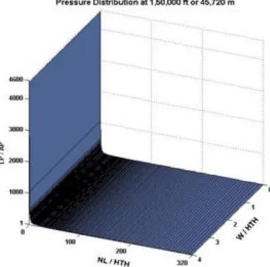
E. Pressure Distribution
Fig. 20. Mach Distribution along nozzle length at 200000ft
Fig. 19. Mach Distribution along nozzle height at 200000ft
Fig. 21. Mach Distribution along nozzle height at 300000ft
Fig. 22. Mach Distribution along nozzle length at 300000ft
Fig. 23. Pressure distribution along height at 0ft
Fig. 25. Pressure distribution along height at 10000ft
Fig. 26. Pressure distribution along length at 10000ft
Fig. 27. Pressure distribution along height at 50000ft
Fig. 28. Pressure distribution along length at 50000ft
Fig. 29. Pressure distribution along height at 150000ft
145103-6868-IJET-IJENS © June 2014 IJENS
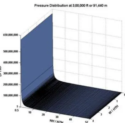
I J E N S The investigation was carried out to generate supersonic nozzle profile with LP/AP unity at the exit. For 0-3,00,000ft the ambient pressure ranges 101.33-0.00000109KPa. The investigation could be carried to altitude higher than 3,00,000ft. Since the profile remains unchanged from the altitude of 1,50,000ft, it is not worthwhile anymore to carry on the investigation any further.
Pressure distribution for the maximum thrust becomes steeper as the altitude increases. Since LP/AP at outlet expected to be unity, the pressure distribution is expected to be steeper at the location closer to the throat i.e. in vicinity of expansion fan.
V. CONCLUSION
The aim of this investigation was to develop a code which will enable the designer to optimize the supersonic nozzle for different altitudes. Since it was aimed to maintain LP/AP unity at the exit, for pressure in vincinity of vacuum the length was supposed to be infinite. By the investigation, the required length and height of the supersonic nozzle is calculated for the altitude where the pressure is close to null. It is now pellucid enough to realize that the additional length of nozzle is utterly infertile beyond a particular range of altitude. The results obtained from this investigation will also be conducive to consolidate the design of variable length supersonic nozzle.
REFERENCES
[1] Martin J. L. Turner, “Rocket and Spacecraft Propulsion- Principles,
Practice and New Developments” Third Edition.
[2] John D. Anderson, Jr., “Fundamentals of Aerodynamics”, 3rd printing
1988.
[3] Argow, B.M. abd Emanuel, G.,1988. Comparison of Minimum Length
Nozzles, Journal of Fluids Engineering, Vol. 110, pp. 283-288.
[4] Zebbiche, T. and Youbi, Z., 2005. Design of two Dimensional
Supersonic Nozzle at high temperature application, Application for air, DGLR 2005-257, German Aerospace Congress 2005, pp. 26-29, Friendrichshafen, Germany.
Fig. 31. Pressure distribution along height at 200000ft
Fig. 32. Pressure distribution along length at 200000ft
Fig. 33. Pressure distribution along height at 300000ft
[5] John D. Anderson, Jr., “Modern Compressible Flow With Historical Perspective”, 2nd Edition.
[6] Zebbiche, T. and Youbi, Z., 2005. Parameter of Supersonic Flow at high
temperature, Application for air, 4th International Conference on Heat transfer, Fluid Mechanics and Thermodynamics HEFAT, 19-22, Sep. 2005, Caire Egypt.
[7] Michel A. Saad, “Compressible Fluid Flow”, 2nd Edition.
[8] Patrick H. Oosthuizen, William E. Carscallen, “Compressible Fluid
Flow”.
[9] Saito, S.A., and Young, J.B., “Numerical investigations of shock waves
in gas-particle mixtures, ” shock waves, Vol. 13.
[10] Papamoschou, D., and Zill, A., “Fundamental Investigation of