Assessment Of Rock Slope Stability Along Minas
Road, Tons Valley, Uttarakhand Himalaya
Gambhir singh chauhan, h.c. Nainwal
Abstract: Slope stability analysis along the Minas road was carried out at 7 locations. Limestone, sandstone and slates are the main
rock types. Geotechnical Data for Rock Mass Rating (RMR) were taken from each location for the rock mass classification. The rock samples were also collected for the lab analysis. The stereographic projections of rock joints were plotted for Kinematic analysis and different slope failures (planar and wedge) were identified. Geological cross section of each rock slope was prepared to show the orientation of different sets of joints with respect to the slope face. Finally the Factor of safety (FOS) of each rock slopes were determined.It was found that among the 7 rock slopes 3 falls in good and 4 in fair RMR class. The Kinematic analysis shows th at2 rock
slope form planar failure and5wedge failures. The Factor of safety analysis depicts that 3 rock slopes have a FOS value above 1 and
form stable slopes while 4 rock slopes shows a FOS value near and below 1 which represent partially stable and unstable slopes.
Keywords : Slope stability, Tons valley, Kinematic analysis, Factor of safety, RMR, UCS, Planar failure —————————— ——————————
1
INTRODUCTION
Slope instability problems are common in hilly terrain mainly along the roads and highways. Rocks in the Himalayan terrain are highly deformed with a number of structural discontinuities. Slopes of an area become unstable either due to natural process or anthropogenic activities. Road cutting causes the steepening of slopes and exposer of more discontinuities along which a slope may fail. Slope stability of an area depends on different properties of rock mass of that area. The Rock mass along a road section can be classified into different RMR classes to analyze the slope stability condition. The FOS analysis of an area is carried out to estimate the stability condition of the slope. For this purpose various numerical methods are used to calculate the FOS of a slope. In this analysis a slope is categorised into stable, partially stable and unstable classes. Slope stability and landslide study along the highways and roads were carried out in past by various researchers like, [1] carried out the Study of landslides in Mandakini valley, Stability analysis of Kaliyasaur landslide along NH-58 [2], Landslide study on the Berinag Munsiyari road, Pithoragarh [3], Cut slope stability analysis in Rudraprayag district of Uttarakhand using CSMR and kinematic analysis [4], Numerical slope stability analysis [5], The study of rockslides /cut slopes and their mitigation measures [6], Rock mass Assessment along the Sutlej river, [7], Assessment of Rock fall hazard along a NH-58 in the Alaknanda Valley using Kinematic analysis [8], Study of slopes along the NH-58 using SMR and kinematic analysis approach [9], Stability analysis of Lakhwar dam reservoir [10],Stability analysis of slope failures along NH-305, India [11], Stability analysis of landslides along Balia Nala, Nainital Uttarakhand [12], Stability analysis of the Pawari landslide, Himachal Pradesh [13], Landslide stability analysis in Rudraprayag and Agastyamuni, Uttarakhand [14], Stability analysis of rock slopes for planar mode of failure [15].Study area lies along Minas road which passes along the Tons valley and connect the pilgrimage, tourist places such as Hanol, Tuni, Harkidoon and various villages of Uttarakhand with the main city. Minas road gets blocked in raining season due to the slope instability problem which cause the interruption in transportation. Slope stability study along the road section is helpful to know the causes of slope failures and their mitigation measures. In present work stability analysis of unstable Rock slopes located along the minas road was carried out (Fig 1).
2. STUDY AREA
The area of study is located between latitude 30°36'30"N- 30°46'0''N and longitude 77°40'0''E-77°49'0''E and lies in the survey of India toposheet no 53F/14 and 53 F/10 along the minas road in the Tons valley, Dehradun district of Uttarakhand (Fig.1). The study area falls in the lesser Himalaya zone and is characterized by the tropical monsoon climate. The major rainfall in the study area occurs from mid-June till early October.
3. GEOLOGICAL SETUP
The present study area is located in the lesser Himalaya covering sedimentary and metamorphic rocks of the Chakrata, Deoban, Mandhali, Chandpur Formations and Bansa limestone. Slate, sandstone and quartzite are the rock types of the Chakrata Formation and limestone is the main rock type of Deoban Formation. The Mandhali and Chandpur Formations are dominantly consists of slate. ___________________________________
Gambhir Singh Chauhan Research Scholar Department of Geology, HNB Garhwal University, Srinagar Garhwal, Uttarakhand, 246174 E-mail: gambhirchauhan89@gmail.com
4884 Fig.1 Geological map of the study area with line of
geological cross section
Geology of study area has been contributed by different authors as, [16], [17], [18] etc. The structural features of study area are Tons thrust, Amtiyar gad thrust and Deoban fault. Different types of fold have developed in the rock mass due to multiple phases of deformation [19]. There are 3 sets of joints with random sets present in the rock mass of the study area.
4. METHODOLOGY
Using the geological map of Valdiya [20] as the base map, the detail geological mapping of the study area was carried out. Data of each slope were taken in field using GPS and cross section profiles were prepared using Alos Palsar Dem with 12.5 m spatial resolution. Field data was imported in Arc-GIS 10.5 and final map was prepared.
4.1 Rock Mass Rating
RMR of the rock slopes is based on the 5 parameters such as, Uniaxial compressive strength (UCS), Joint spacing, Joint condition, Rock quality designation (RQD), Water condition [21]. The condition of discontinuities is depends on the aperture, persistence, filling material and weathering condition of joints. The UCS data was collected from the field using L-type Schmidt hammer rebound according to ISRM [22] and converted into UCS using equation given by Derre and Miller [23]. RQD was determined based on number of joints per unit volume (JV) according to
Palmstorm [24].
RQD = 115-3.3 *JV
4.2 Kinematic and Factor of safety analysis
At the first step stereographic projections were prepared and joint set responsible for the slope failure were identified using kinematic analysis [25]. This method is highly applied in rock slope stability analysis. Orientation of discontinuities, slope angle and angle internal friction (Փ) are used in kinematic analysis. FOS is calculated by dividing the resisting forces from driving forces of a rock slope. The FOS analysis of plane and wedge failures of different rock slope was performed according to Hoeks and Bray [26]. The value of FOS above 1 indicates stable slopes and value below 1 depicts unstable slope condition [27]. The value of cohesion (C) and internal friction (Փ) for each rock type were taken according to Hoek and Brey [26]. Internal friction angle of 25○ was taken for slate and 35○ for sandstone and limestone while Cohesion of 25 MPa was taken for slate and 30 MPa for sandstone and limestone. The equation 1 and 2 were used for FOS analysis of planar and wedge failures. FOS analysis of planar failure is determined for dry condition.
F = C. A + W. cosѱp. tan ɸ/ W. sinѱp
(1)
Where cohesion, area and weight of sliding block is represented by C, A and W respectively. ѱp and ѱf
represents the dip amount of joint and angle of slope face.
𝐹 = sin β tanɸ 1
sin(𝜉/2)𝑡𝑎𝑛 𝜑
(2)
Where angle of intersection between discontinuities and the bisector is denoted by β, angle of internal friction, wedge angle and plunge of wedge are represented by ɸ, ξ and φ respectively. Stereographic projection was used to determine the different factors used in the equation.
5. RESULT AND DISCUSSIONS
Results of the preset study are presented in tables and figures. Rock mass of different slopes falls in good and fair RMR category (Table.1). RMR rock mass of an area are used in civil engineering construction and slope stability analysis. Kinematic analysis of rock mass depicts the type and mode of slope failures. Wedge failures were found more common in the rock mass (Table. 2).
Table.1 Results of RMR of each location
Locati -on
RL UCS Rating & rating RQD & rating Joint spacing & Rating Joint condition & Rating Water Cod & Rating
RMR RMR Class L1 39 103 100-250
(12) 33.5%
(8)
6-10 cm (8)
19 Dry
(15)
62 Good Rock
L2 42.2 85.83 50-100 (7)
42.4% (8)
6-12 cm (8)
15 Dry (15)
53 Fair Rock
L3 42.5 60 50-100 (7)
82.6% (17)
20-50cm (10)
18 Dry
(15)
67 Good Rock
L4 35 60 50-100 (7)
55.4% (13)
30-60 cm (10)
22 Dry
(15)
67 Good Rock
L5 25 45.07 25-50 (4)
45.7% (8)
< 6 cm (5)
15 Dry
(15)
47 Fair Rock
L6 25 45.07 25-50 (4)
32.5% (8)
8-14 cm (8)
17 Dry
(15)
52 Fair Rock
L7 37.5 77.25 50-100 (7)
72% (13)
6-10 cm (8)
22 Dry
(15)
65 Good Rock
for UCS analysis according to ISRM [22]. UCS of 2 core samples of Bansa limestone is identified 54 and 123 MPa and 2 core samples of purple sandstone shows an UCS value of 28 and 98 MPa (Fig.5). Gray sandstone and slate shows a low UCS value. UCS value of rocks identified in lab and from Schmidt hammer have a minor difference. Description of each rock slope (L1 to L7) with cross section is given below.
Table .2 Results of Kinematic analysis and Factor of safety
Location
Rock type Joint trend
Slope face Angle (○)
Failure type
Responsible joint FOS
L-1 Limestone
J1 210°/25 J2 300°/70
J3 240°/85 N 175
○/55 Planar J1
1.20
L-2 Sandstone
J1 N70/40 J2160°/75
J3 29°/70 N225
○/70 Wedge J1 &J2
0.91
L-3 Slate
J1 50°/65 J2 305°/78
J3 200°/55 N225
○/65 Wedge J1 &J2
1.02
L-4 Sandstone J1 50/60 J2 280°/55
J3 155°/55 N305
○/70 Wedge J1 &J2
0.73
L-5 Slate
J1 55°/60 J2 335°/75 J3 55°/80
N/70
Wedge
J1 &J2
1.31
L-6 Slate
J1 220°/55 J2 330°/75 J3 65°/65
N300/70 Wedge J1& J2 1.05
L-7 Slate
J1 200°/50 J2 50°/25 J3 320°/70
N200/65 Planar J1 1.43
L-1 – Siliceous Bansa limestone is the rock type at L-1
which falls in fair RMR class (Table.1). The cross section along A-A' was prepared which shows relationship between the different sets of joint and slope face (Fig. 2). The height of slope is 220 m and road is located on the slope at an elevation 120 m. The slope is unstable and form planner failures along J-1 joint sets (Fig.3). The direction of dip of slope is N175 with a dip amount of 55○. The trend of joint set J-1 is N 195/30○. The Slope wash material is present on the slope. FOS determined using equation 1 is 1.20 which shows that slope is partially stable (Table.2).
L-2- The purple colorsandstone of the Chakrata Formation
is the main rock type at Location 2 which falls in fair RMR category. The cross-section of slope along B-B' and stereographic projection are given in Fig.3a & 3b. The height of road cut slope is 150 m and average dip is 55○. Rock slope is unstable and form wedge failures between J1-J2 and J2 - J3 joint sets. The plunge of wedge failure between J1- J2 is N 82/40○and J2-J3 is N85/45○. The rock mass is highly deformed and moderately weathered and covered by overburden material. Factor of safety value 0.91 was determined for wedge failures between J1 and J2 joint sets.
Fig.2 Geological cross Section of different locations (A-A', B-B', C-C', D-D', E-E', F-F', G-G') along the section line
shown in Fig.1
L-3 - Slate of the Chakrata Formation is the main rock type
at L-3. Rack mass falls in good RMR category. The cross-section of slope along C-C' shows a height of 120 m and is covered by debris (Fig. 4a). The dip of natural slope angle is about 45○ but due to road cut the slope angle has increased about 65 to 70○. A wedge failure is found between J1 and J2 with a plunge of N13/60 (Fig 4b). FOS of 1.02 was determined which shows that slope is partially stable.
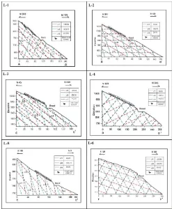
4886 Fig.3 Stereographic projection of different locations (L1, L2,
L3, L4, L5, L6, L7) showing different types of failures with respect to the slope
L-5 – Rock mass at L-5 falls in good RMR category and slate of The Mandhali Formation is the main rock type. The cross section along E-E' and stereographic projection shows wedge failures between J1 - J2 and J2-J3 joint sets. The dip of wedge between J1- J2 and J2-J3 is N39/58○and N340/60. The height of slope is 140 m along the cross- section and road is located at an elevation of 30 m on the slope. Factor of safety value of 1.31 is determined for this slope.
L-6- Rockmass falls in fair RMR category and slate is the main rock type at L-6. Geological cross section along F-F' was drawn and kinematic analysis shows wedge failures between J1 and J2 with a plunge of 260/48○ (Fig 2&3). The slope height is 130 m and road is located on the slope at an elevation of 60 m. The FOS value of 1.05 is identified for this slope which depicts that slope is partially stable.
Fig.4.Geological cross section and stareographic projection of location-7
L-7- Slate is the rock type at L-7 which forms planar failures along J-1 joint sets which has a trend of N220/60○. The orientation of discontinuities is shown in cross-section G-G' and stereographic projection.The height of slope is 180 m and the road is located on the slope at an elevation of 70 m. Rock mass falls in good RMR class and is covered by overburden. The angle of internal friction is kept 25○and cohesion 25 MPa to determine the FOS of 1.43 for this slope.
Fig.6.Field photos (A,B,C,D,E,F) of different locations. A&F shows planer failure in limestone and slate, B,C,D,E
represent wedge failures in sandstone and slate
6. CONCLUSION
Slope stability analysis carried out along the road section gave different results. It was found that out of 7 rock slopes 4 rock slopes falls in fair and 3 in good RMR category. Maximum value of RMR is found 67 and minimum 47. The kinematic analysis of discontinuities depicts that 5 rock slopes form wedge failures and 2 planar failures. FOS analysis depicts that The value of FOS at locations L1, L5 & L7 is above 1 which shows stable condition. Slopes at location L3 and L6 have a FOS value near 1 which represents partially stable slope while remaining locations L2, L4 form unstable slope with a FOS value below 1.
7 REFERENCES
[1] Joshi, V., Naithani, A. K., & Negi, G. C. S. (2001). Study of landslides in Mandakini river valley, Garhwal-Himalaya, India. GAIA, 16, 87-95.
[2] Nainwal, H.C. (2002). Geological Analysis of Kaliasaur Landslide Zone, Alaknanda Valley, Garhwal Himalaya, Uttaranchal. In: H.C. Nainwal and C. Prasad (eds.), Proceedings of National Seminar on Geodynamics, 164-181.
[3] Sarkar, S., & Kanungo, D. P. (2010). Landslide disaster on berinag–munsiyari road, pithoragarh district, uttarakhand. Current Science, 98(7), 900-902.
[4] Umrao, R. K., Singh, R., Ahmad, M., & Singh, T. N. (2011). Stability analysis of cut slopes using continuous slope mass rating and kinematic analysis in Rudraprayag district, Uttarakhand. Geomaterials, 1(03), 79.
[5] Kainthola, A., Verma, D., Thareja, R., & Singh, T. N. (2013). A review on numerical slope stability
analysis. International Journal of Science, Engineering and Technology Research (IJSETR), 2(6), 1315-1320.
[6] Naithani, A. K., Jain, P., & Singh, L. G. (2015). The problems of rockslides/cut slopes and their mitigation measures–a case study. Indian Landslides, 8, 1-8.
[7] Singh, P. K., Kainthola, A., & Singh, T. N. (2015). Rock mass assessment along the right bank of river Sutlej, Luhri, Himachal Pradesh, India. Geomatics, Natural Hazards and Risk, 6(3), 212-223.
[8] Gupta, V., Tandon, S.R. (2015). Kinematic rock fall hazard assessment along a transportation corridor in the Upper Alaknanda Valley Garhwal Himalaya India. Bulletin of Engineering Geology and the Environment, 74, 315-326.
[9] Siddique, T., Alam, M. M., Mondal, M. E. A., & Vishal, V. (2015). Slope mass rating and kinematic analysis of slopes along the national highway-58 near Jonk, Rishikesh, India. Journal of Rock Mechanics and Geotechnical Engineering, 7(5), 600-606.
[10] Anbalagan, R., & Parida, S. (2013) Geotechnical Studies of Reservoir Area of Lakhwar Dam Project, Garhwal Himalaya, India.
[11] Mahanta, B., Singh, H. O., Singh, P. K., Kainthola, A., & Singh, T. N. (2016). Stability analysis of potential failure zones along NH-305, India. Natural Hazards, 83(3), 1341-1357.
[12] Kumar, M., Rana, S., Pant, P. D., & Patel, R. C. (2017). Slope stability analysis of Balia Nala landslide, Kumaun Lesser Himalaya, Nainital, Uttarakhand, India. Journal of Rock Mechanics and Geotechnical Engineering, 9(1), 150-158.
[13] Kumar, V., Gupta, V., & Jamir, I. (2018). Hazard evaluation of progressive Pawari landslide zone, Satluj valley, Himachal Pradesh, India. Natural Hazards, 93(2), 1029-1047.
[14] Raghuvanshi, T. K. (2019). Governing factors influence on rock slope stability–Statistical analysis for plane mode of failure. Journal of King Saud University-Science. [15] Pradhan, S. P., Vishal, V., & Singh, T. N. (2018). Finite
element modelling of landslide prone slopes around
Rudraprayag and Agastyamuni in Uttarakhand
Himalayan terrain. Natural Hazards, 94(1), 181-200.
[16] Raghuvanshi, T. K. (2019). Governing factors influence on rock slope stability–Statistical analysis for plane mode of failure. Journal of King Saud University-Science. [17] Rupke, J. (1974). Stratigraphy and structural evolution of the Kumaon Lesser Himalaya. Sedimentary Geology, 11, 81-265.
[18] Gansser, A. (1964). Geology of the Himalaya. Interscience Publications, London. 273p.
[19] Saxena, S.P. Srivastava, M.C. (1991). Simla Formation and Morar- Chakrata Formation- A comparative study with reappraisal of status of Simla Group. Records of the Geological Survey of India, 124, 221-224.
[20] Srivastava, V., Lakhera, R.C. (2007). Geology, structure and tectonics of the Kwanu- Shillai area, Uttaranchal- Himachal Pradesh, using remote sensing techniques. In: Saklani, P.S. (ed.) Himalaya (Geological Aspects), 5, Satish Serial Publishing House, New Delhi, 229-264. [21] Valdiya, K. S. (1980). Geology of kumaun lesser
Himalaya. Wadia Institute of Himalayan Geology
4888 International Congress on Rock Mechanics, ISRM
Montreux, Balkema, Rotterdon, 2, 51-58.
[23] ISRM, (2007). The complete ISRM suggested methods for rock characterization, testing and monitoring: 1974-2006. Springer.
[24] Deere DU, Miller RP (1966) Engineering classification and index properties for intact rocks. Tech Rep no. AFNL-TR. Air Force Weapons Lab, Wright-Patterson Air Force Base, p 301.
[25] Palmstrom, A. (1982). The volumetric joint count - a useful and simple measure of the degree of jointing. Proceedings International Congress of IAEG, New Delhi, 221 - 228.
[26] Markland, J.T. (1972). A useful technique for estimating the stability of rock slopes when the rigid wedge sliding type of failure is expected. Imperial College of Rock Mechanics Research Reprint, 19-10.
[27] Hoek, E., Bray, J.W. (1981). Rock Slope Engineering. 3rd ed. Institution of Mining and Metallurgy, London, 359p.