INTRODUCTION
In recent years there has been a growing recognition that more sustainable development approaches are required across both the private and public sector for developing alternative fossil fuels. To reduce the dependency on fossil fuel it is essential to trigger & promote the sustainable sources of energy that will be available for longer period of time. Fuel material and consumer goods has increased significantly and will continue to spiral upwards during the early part of the 21st century. The main driver for demand is not due to population increase, but the large increase in per capital consumption that accompanies the improving standards of living throughout the world. Biofuels are alternative renewable fuels that have received considerable attention in the recent past. With increasing demand on the use of fossil fuels greater threat to clean environment is being posed. Burning of fossil fuel is associated with emissions like CO2,
Characterization and performance of Bio-diesel and its
blends in CI engines by studying combustion and
emission characteristics
PREETI JAIN and SUCHETA KHOWAL
Medi-Caps institute of Technology and Management, Indore (India). (Received: January 02, 2010; Accepted: February 18, 2010)
ABSTRACT
In the present study biodiesel is collected from Bindle group and it blended in various proportions with diesel were studied. The torque, brake power and fuel consumption values associated with these fuels were determined under certain operating condition. Maximum brake power for all the blend as well as diesel is obtained in the speed range of 1520 rpm. Maximum Brake power for JB 80% is 1.83 Kw at 1500 rpm & for diesel is 1.82 Kw at 1444 rpm. Increase in power may be due to complete combustion of oxygenated fuel. With increase in speed, specific fuel consumption first decreases and than increases. Specific fuel consumption (sfc) also increases with increase in blend percentage. All the blend gave minimum sfc at 1444 rpm for diesel is 0.49 kg/kwh, JB 20% at 1490 rpm is 0.45 kg/kwh, JB 40% at 1480 rpm is 0.51 kg/kwh,JB60% at 1492 rpm is 0.52 kg/kwh, JB 80% at 1500 rpm is 0.49kg/kwh.. The products of Tran’s esterification were evaluated by comparing physical characteristics of biodiesel oil. The biodesel were then tested in diesel engine to observe their actual performance emission. This paper introduces an elegant method for the above required analysis by establishing a definite relationship between fuel properties and engine performance.
Key words: Biodiesel, blending, esterification, specific gravity, brake power, torque.
CO, SOx, NOx and particulate matter that are global source of emission2. These emissions cause pollution and make the environment polluted. The ideal alternative fuel will be one in which the engine would burn much more clearly than conventional gasoline fuel and would at the same time require less modification. Bio-diesel was used as fuel of a direct injection CL engines. One of the biggest advantages of biodiesel compared to many other alternative transportation fuels is that it can be used in existing diesel engines with some modification, and can be blended in at any ratio with diesel. One of the impor tant concer ns about wide-scale development of biodiesel is if it would displace croplands currently used for food crops4.
MATERIAL AND METHODS
measurement of fuel - air consumption, exhaust temperature, coolant inlet-outlet temperature and flow rate. Engine is directly coupled to an electrical dynamometer, used to start the engine. Out of two-panel left one contains the electrical controls for controlling the dynamometer engine speed is measured with an electronic digital meter. Inlet and
outlet temperature measured by thermocouples in the water jacket flow rate of water is noted by Rota meter. For measuring exhaust gas temperature one thermocouple is fixed to the exhaust gas pipe of the engine to measure and the temperature is displayed digitally7.
Test procedure
Engine is started by cranking then after stabilizing measure rpm, inlet, outlet temperature of coolant, exhaust temperature, pressure; fuel consumption time in sec is measured by stop watch at no load condition. Repeat the process by increasing load.
Sample Calculation
Blend used-100 %, 80%, 60%, 40%, 20% and pure diesel
Load given- 2-25
Time recorded for consumption of 20 ml of fuel
Bore dia (D) 80mm
Stroke length (L) 553cc
Speed 1500rpm
1. Power developed = (P* L*A*N*k)/ (60*n) K=no. of cylinder n=1 for 2 stroke engine 2. Torque N-m= (Power*1000*60)/ (2*ð*N)
3. Mass flow rate mf (Kg/sec) = (Density*Volume)/ time
4. Efficiencyη % =Power* 100/ (mf *CV) Engine Specification
Stroke 110 mm
Speed 1500 rpm
No. of cylinders 01
Type of ignition Compression Ignition Type of cooling water cooled
RESULTS AND DISCUSSION
Table1-6(a) Shows that brake power increases as the blend % increases, this is due to complete combustion of fuel, maximum brake power for all the blend as well as diesel is obtained in the speed range of 1520 rpm. Max. Brake power for JB 80% is 1.83 Kw at 1500 rpm & for diesel is 1.82 Kw at 1444 rpm. Increase in power may be due to complete combustion of oxygenated fuel.
Table 1-6 (b) Shows that with increase in speed, specific fuel consumption first decreases and than increases. Specific fuel consumption(sfc) also increases with increase in blend %.All the blend gave minimum sfc at 1444 rpm for diesel is 0.49 kg/kwh, JB 20% at 1490 rpm is 0.45 kg/kwh, JB 40% at 1480 rpm is 0.51 kg/kwh,JB60% at 1492 rpm is 0.52 kg/kwh, JB 80% at 1500 rpm is 0.49kg/kwh.
Table 2(a): 20% Biodiesel
S. RPM Load Tim T1 T2 T3 T4 T5 H1- Water Water
No of (W-S) e for (0C) (0C) (0C) (0C) (0C) H2 flow to flow to
Crank kg 20ml (mm of Calorimeter Engine
shaft fuel water) LPM LPM
(sec)
1 1524 0 184 33 46 36 135 65 12 2.1 1.95
2 1522 1.2 158 33 47 36 146 69 12.5 2.1 1.95
3 1520 2.5 130 33 47 36 156 72 12.1 2.1 1.95
4 1516 5 108 33 48 37 177 76 11.8 2.1 1.95
5 1510 7.5 89 33 50 38 198 81 11.5 2.1 1.95
6 1500 10.8 80 33 53 39 217 86 11 2.1 1.95
7 1490 13.2 78 33 55 39 243 92 10.9 2.11 1.95
Table 1(b): Diesel Only
S. RPM of BP Fuel Bsfc Bth eff Air
No crank (watts) consumption (kg/Kwh) consumption
shaft (Kg/Kwh) (Kg/Sec)
1 1520 0 0.345762712 0.001537502
2 1524 66.56505 0.402631579 3.048693 1.4004 0.001569207
3 1518 424.3391 0.485714286 1.84637 7.4002 0.001543895
4 1510 765.0613 0.612 0.799936 10.589 0.001524636
5 1500 1100.682 0.816 0.741359 11.426 0.00150513
6 1492 1459.749 0.85 0.582292 14.547 0.001472046
7 1444 1829.054 0.9 0.492058 17.215 0.00146534
Table 1(a): Diesel only
S. RPM Load Tim T1 T2 T3 T4 T5 H1- Water Water
No of (W-S) e for (0C) (0C) (0C) (0C) (0C) H2 flow to flow to
Crank kg 20ml (mm of Calorimeter Engine
shaft fuel water) LPM LPM
(sec)
1 1520 0 177 33 45 36 145 67 12 1.95 1.95
2 1524 0.5 152 33 46 37 153 69 12.5 1.95 1.95
3 1518 3.2 126 33 46 37 167 73 12.1 1.95 1.95
4 1510 5.8 100 33 47 37 186 77 11.8 1.95 1.95
5 1500 8.4 75 33 50 39 224 83 11.5 1.95 1.95
6 1492 11.2 72 33 55 39 249 93 11 1.95 1.95
Table 3(a): 40% Biodiesel
S. RPM Load Tim T1 T2 T3 T4 T5 H1- Water Water
No of (W-S) e for (0C) (0C) (0C) (0C) (0C) H2 flow to flow to
Crank kg 20ml (mm of Calorimeter Engine
shaft fuel water) LPM LPM
(sec)
1 1526 0 181 33 45 36 134 66 12.5 2.1 1.95
2 1520 1.1 154 33 46 36 144 70 12.4 2.1 1.95
3 1514 2.7 131 33 47 36 1576 73 12.6 2.1 1.95
4 1512 5.1 104 33 49 37 177 78 11.8 2.1 1.95
5 1500 7.4 89 33 50 38 197 83 11.7 2.1 1.95
6 1490 10.6 78 33 53 38 216 88 11.4 2.1 1.95
7 1480 13.4 69 33 55 39 243 95 10.6 2.1 1.95
Table 3(b): 40% biodiesel
S. RPM of BP Fuel Bsfc Bth eff Air
No crank (watts) consumption (kg/Kwh) consumption
shaft (Kg/Kwh) (Kg/Sec)
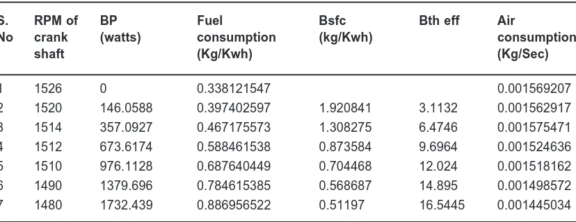
1 1526 0 0.338121547 0.001569207
2 1520 146.0588 0.397402597 1.920841 3.1132 0.001562917
3 1514 357.0927 0.467175573 1.308275 6.4746 0.001575471
4 1512 673.6174 0.588461538 0.873584 9.6964 0.001524636
5 1510 976.1128 0.687640449 0.704468 12.024 0.001518162
6 1490 1379.696 0.784615385 0.568687 14.895 0.001498572
7 1480 1732.439 0.886956522 0.51197 16.5445 0.001445034
Table 2(b): 20% biodiesel
S. RPM of BP Fuel Bsfc Bth eff Air
No crank (watts) consumption (kg/Kwh) consumption
shaft (Kg/Kwh) (Kg/Sec)
1 1524 0 0.332608696 0.001537502
2 1522 159.5465 0.387341772 2.427768 3.489 0.001569207
3 1520 331.9517 0.470769231 1.418186 5.9728 0.001543895
4 1516 662.1563 0.566666667 0.85579 9.898 0.001524636
5 1510 989.3035 0.687640449 0.695075 12.187 0.00150513
6 1500 1415.163 0.765 0.540574 15.67 0.001472046
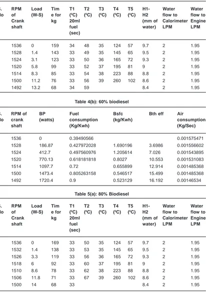
Table 5(a): 80% Biodiesel
S. RPM Load Tim T1 T2 T3 T4 T5 H1- Water Water
No of (W-S) e for (0C) (0C) (0C) (0C) (0C) H2 flow to flow to
Crank kg 20ml (mm of Calorimeter Engine
shaft fuel water) LPM LPM
(sec)
1 1536 0 169 33 50 35 124 57 9.7 2 1.95
2 1532 1.4 138 33 53 35 145 65 9.5 2 1.95
3 1526 3.3 119 33 56 36 165 72 9.3 2 1.95
4 1518 6 92 33 60 37 195 81 9 2 1.95
5 1510 8.6 78 33 62 38 223 88 8.8 2 1.95
6 1506 11.8 71 33 67 39 260 102 8.6 2 1.95
7 1500 14 68 33 8.4 2 1.95
Table 4(b): 60% biodiesel
S. RPM of BP Fuel Bsfc Bth eff Air
No crank (watts) consumption (kg/Kwh) consumption
shaft (Kg/Kwh) (Kg/Sec)
1 1536 0 0.39490566 0.001575471
2 1528 186.87 0.427972028 1.690196 3.6986 0.001556602
3 1524 412.7 0.497560976 1.205614 7.026 0.001543895
4 1520 770.13 0.618181818 0.8027 10.553 0.001531083
5 1514 1097.7 0.72 0.655899 12.914 0.001485368
6 1500 1473.4 0.805263158 0.546517 15.499 0.001485368
7 1492 1720.4 0.9 0.523129 16.192 0.00146534
Table 4(a): 60% Biodiesel
S. RPM Load Tim T1 T2 T3 T4 T5 H1- Water Water
No of (W-S) e for (0C) (0C) (0C) (0C) (0C) H2 flow to flow to
Crank kg 20ml (mm of Calorimeter Engine
shaft fuel water) LPM LPM
(sec)
1 1536 0 159 34 48 35 124 57 9.7 2 1.95
2 1528 1.4 143 33 49 35 145 65 9.5 2 1.95
3 1524 3.1 123 33 50 36 165 72 9.3 2 1.95
4 1520 5.8 99 33 52 37 195 81 9 2 1.95
5 1514 8.3 85 33 54 38 223 88 8.8 2 1.95
6 1500 11.2 76 33 56 39 260 102 8.6 2 1.95
Table 6(a): 100% Biodiesel
S. RPM Load Tim T1 T2 T3 T4 T5 H1- Water Water
No of (W-S) e for (0C) (0C) (0C) (0C) (0C) H2 flow to flow to
Crank kg 20ml (mm of Calorimeter Engine
shaft fuel water) LPM LPM
(sec)
1 1520 0 157 52 45 54 140 76 9.8 1 2
2 1516 1.6136 136 57 46 73 135 86 9.6 1 2
3 1504 3.4103 103 62 52 88 178 95 9.4 1 2
4 1480 890 90 75 57 100 207 108 9.4 1 2
Table 6(b): 100% biodiesel
S. RPM of BP Fuel Bsfc Bth eff Air
No crank (watts) consumption (kg/Kwh) consumption
shaft (Kg/Kwh) (Kg/Sec)
1 1520 0 0.389808917 0.001389435
2 1516 211.89 0.45 2.123743 3.9885 0.001375184
3 1504 446.7 0.594174757 1.330136 6.3682 0.001360784
4 1480 1034.3 o.9 0.657455 12.884 0.001360784
Table 5(b): 80% biodiesel
S. RPM of BP Fuel Bsfc Bth eff Air
No crank (watts) consumption (kg/Kwh) consumption
shaft (Kg/Kwh) (Kg/Sec)
1 1536 0 0.362130178 0 0.001382328
2 1532 187.12 0.443478261 1.870072 3.574 0.001368003
3 1526 439.91 0.514285714 1.49081 7.2455 0.001353526
4 1518 795.64 0.665217391 0.836083 10.131 0.001331516
5 1510 1134.4 0.784615385 0.691656 12.247 0.001316638
6 1506 1552.4 0.861971831 0.555258 15.255 0.00130159
7 1500 1834.5 0.9 0.490605 17.266 0.00128636367
CONCLUSION
Application of bio-diesel and its blend cannot be limited only as a fuel in CL engines. In future biodiesel can also be used as an alternative for coal, in thermal power plant; the need is to estimate the cost requirement and the set up
0 500 1000 1500 2000
RPM of crank s haft
BP (watts )
Fig. 1(a): 0 500 1000 1500 2000
RPM of crank shaft
BP (w atts)
Fig. 2(a): 20%
0 500 1000 1500 2000
RPM of crank shaft Bsfc (kg/Kwh)
Fig. 3(b): 40%
0 500 1000 1500 2000
RPM of crank s haft
BP (w atts )
Fig. 3(a): 40%
0 500 1000 1500 2000
RPM of crank s haft
BP (w atts )
Fig. 4(a): 60%
0 5 0 0 1 0 0 0 1 5 0 0 2 0 0 0
RP M o f c r a n k s h a f t
B s f c ( k g /Kw h )
Fig. 4(b): 60%
0 500 1000 1500 2000
RPM of crank s haft
Bsfc (k g/Kw h)
Fig. 1(b): 0 500 1000 1500 2000
RPM of crank shaft
Bs fc (kg/Kw h)
Fig. 1(b): 20%
0 500 1000 1500 2000
RPM of crank s haft
BP (w atts )
Fig. 5(a): 80%
0 5 0 0 1 0 0 0 1 5 0 0 2 0 0 0
RP M o f c r a n k s h a f t
B s fc ( k g /K w h )
ACKNOWLEDGEMENTS
The authors are thankful to Director and Head of Mechanical Dept. MITM for providing the working
0 500 1000 1500 2000
RPM of crank shaft
BP (w atts)
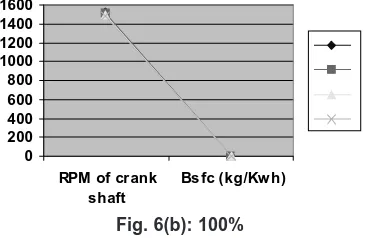
Fig. 6(a): 100%
0 200 400 600 800 1000 1200 1400 1600
RPM of crank shaft
Bs fc (kg/Kw h)
Fig. 6(b): 100%
facilities and also thankful to Mr. Arun Bindal (Industrialist) for providing the biodisel for the research.
1. Clarke N. N., Lyons D. W., Class 8 truck emissions testing: the effects of test cycles and data on biodiesel operation, Transactions of the ASAE, 42(5): 1211-1219 (1999). 2. Dorado M. P., Arnal J. M., Gomez, Gil A.,
Lopez F. J., The effect of a waste vegetable oil blend with diesel fuel on engine performance, Transactions of the ASAE, 45(3): 519-523 (2002).
3. Goering C. E., Schwab A. W., Daugherty M. J., Pryde E. H., Heakin A. J., Fuel properties of eleven vegetable oils, Transactions of the SAE, 25(6): 1472-1477, 1483 (1982). 4. Goodrum J. W., Patel, McClendon R. W.,
Diesel injector carbonization by three alternative fuels, Transactions of the ASAE, 39(3): 817-821 (1996).
5. Knothe, Analytical methods used in the production and fuel quality assessment of biodiesel, Transactions of the ASAE, 44(2): 193-200 (2001).
6. Monyem A., Van Gerpen J. H., Canakci M., The effect of timing and oxidation on emissions from biodiesel-fuelled engines,
REFERENCES
Transactions of the ASAE, 44(1): 35-42 (2001).
7. Munack A., Schroeder O., Krahl J., Buenger J., Comr ison of relevant exhaust gas emissions from biodiesel and fossil fuel, Agricultural Engineering Inter national, Available at: http://cigr-ejournal.tamu.edu/ Volume3.html (2001).
8. Peterson C. L., Wagner G. L., Auld D. L., Vegetable oil substitutes for diesel fuel, Transactions of the ASAE, 26(2): 322-327, 332 (1983).
9. Richards I. R., Energy bances in the growth of oilseed rape for biodiesel and of wheat for bioethanol, Levington Agriculture Report, Available at: http://www.biodiesel.co.uk/ levington, accessed 20 April 2005 (2000). 10. Shumaker G. A., McKiossick J., Ferland C.,