Comparison of PMU Placement Techniques For Complete
Observability of Network Using State Estimation
1
Kanika Jain,
2Sumeet Shehrawat
1,2Dept. of Electrical and Electronics Engineering, Amity University, Noida, UP, India
Abstract
Theuse of Phasor Measurement Units (PMUs) enhances the state estimation in terms of accuracy and complete network observability. For the placement of PMUs in the network, algorithm based on integer programming is used.The cost of installation is more using only PMUs for complete observability; in order to make the system economical and yet observable PMU along with injection measurement in conventional state estimation program will be discussed in this paper.Case studies carried out on different sized test systems are presented and the test results of different PMU placement techniques are compared on the basis of economy, accuracy and observability.
Keywords
Hybrid State Estimation, Network Observability, Phasor Measurement Units, State Estimation.
I. Introduction
As the PMUs have become more and more affordable, their utilization will increase not only for substation applications but also at the control centres for the Energy Management Systems (EMS) applications.A PMU placed at a given bus is capable of measuring the voltage phasor of the bus as well as the phasor currents for all lines incident to that bus [2]. Hence, furnishing a selected subset of buses with PMUs can make the entire system observable. This will only be possible by proper placement of PMUs among the system buses. This problem is formulated and solved using graph theoretic observability analysis and an optimization method based on binary integer programming. State estimation is a key element of the online security analysis function in modern power system energy control centres. The function of state estimation is to process a set ofredundant measurements to obtain the best estimate of thecurrent state of a power system. State estimation is traditionallysolved by the weighted least square algorithm withconventional measurements such as voltage magnitude, realand reactive power injection, real
and reactive power flow [3]. The voltage and current phasors
obtained from PMUs can be implemented in the traditional state estimation and the effect of adding PMU measurements on the state estimation solution accuracy will be studied.
A specific model is used to implement both the voltage and line
current phasor measurements into traditional WLS state estimation. In this model, the voltage phasor measurements are used in the
polar coordinates denoted as the angle δi and magnitude Vi for the voltage phasor at the certain bus i, which directly corresponds to
the state variables δi and Vi. The line current phasor are measured in rectangular coordinates, in terms of their real Iij,(r) and imaginary Iij,(i) parts for the current phasor in the branch from bus i to bus j [4]. In this paper different techniques of PMU placement and their comparison is discussed.Only use of PMUs for the observability of the system is highly accurate but at the same time it is very costly. From the economy point of view it is not desirable to install only PMUs for the observability of the system, so in order to minimize the cost of installation injection measurements are
also placed along with the PMUs to make the system observable. Use of injection measurements minimizes the number of PMUs which reduces the cost of installation as well as the accuracy of the system is not affected by a large margin and it stays within the acceptable limit.
In order to implement optimum locations of injection measurements along with PMUs the objective function used
for the optimum placement of PMUs is modified to include the
injection measurements. Then binary integer programming is implemented using MATLAB to this new objective function to obtain the optimum locations.
II. Weighted Least Square State Estimation Method
Weighted Least Square (WLS) method is commonly used to solve the state estimation problem, which is formulated as the following optimization problem:
(1)
Subjected to zi = hi(x) + ri; i = 1… m Where,
m is the number of measurements; n is the number of system states;
zT = [z
1, z2, …….,zm] is the vector of measurement;
hT = [h
1(x), h2(x)…hm(x)] is a nonlinear measurement vector;
xT = [x
1,x2…xm] is the system state vector.
W is the weight matrix, which is defined as the inverse of the
covariance matrix of the measurement errors R:
R = diag[σ12, σ
22,……..,σm2] (2)
At the minimum value of the objective function, the first order optimality conditions have to be satisfied.
These can be expressed in compact form as follows:
(3)
Where
(4)
The nonlinear function g(x) can be expanded into its Taylor series around the state vector xk neglecting the higher order terms. An
iterative solution scheme known as the Gauss-Newton method is used to solve
xk+1 = xk - [G(xk)]-1.g(xk) (5)
Where, k is the iteration index; xk is the solution vector at the k th
iteration; G(xk) is called the gain matrix, and expressed by:
g(xk) = -HT(xk)R-1[z-h(xk)] (7)
Substituting the values of equation(6) and (7) in equation(5) and solving we get:
[G(xk)]∆xk+1 = HT(xk)R-1[z-h(xk)] (8)
Where ∆xk+1 = xk+1 – xk
State vector xk are calculated iteratively until the maximum
variable difference satisfies the condition, ' Max |Δxk|< ε '. Consider
a system having (N) buses; the state vector will have (2N-1) components which are composed of (N) bus voltage magnitudes and (N-1) phase angles.
The three most commonly used measurement used in state
estimation are bus power injections, the line power flows and
bus voltage magnitudes.These measurement equations can be expressed using the state variables. Jacobian matrix H has rows at each measurement and columns at each variable.H matrix components corresponding to these measurements are partial derivation of each variable.
(9)
In this matrix δ and V are state variables, Pi and Qi are real and reactive power injections at bus i. Pij, Qij are real and reactive
power flows from bus i to bus j.
III. Hybrid State Estimation
In a hybrid state estimation the measurements received from the PMUs are incorporated in the traditional state estimation. One PMU can measure the voltage and the current phasors.The voltage phasor measurements are used in the polar coordinates
denoted as the angle δi and magnitude Vi for the voltage phasor at
bus i, which directly corresponds to the state variables δi and Vi. Therefore, there is a linear relation between the voltage phasor measurements and state variables. However, the model of line current phasor measurement is nonlinear and more complicated. The line current phasor are written in rectangular coordinates, in terms of their real Iij,(r) and imaginary I(ij,(i) parts for the current
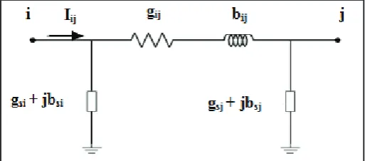
phasor in the branch from bus ito bus j.Considera two-port π-model of a network branch show in fig. 1.
Fig. 1: Model of a Network Branch
Where,
gij+bij is the admittance of the series branch connecting buses i and j;
gsi+bsi is the admittance of the shunt branch connected at bus i. The real and imaginary parts of the current phasor along the branch from bus i to bus j can be expressed as the following formulations, which also represent the nonlinear measurement functions hi(x) relating current phasor measurements to the state variables:
Iij,(r) = (Vicosδi-Vjcosδj)gij– (Visinδi-Vjsinδj)bij + Vicosδigsh -
Vjsinδjbsh (10)
Iij,(i)= (Vicosδi-Vjcosδj)bij+ (Visinδi-Vjsinδj)gij + Vicosδibsh+Vjsinδj
gsh (11)
Their corresponding elements in the Jacobian matrix H can also be obtained by the derivative of the real and imaginary with respect of the angle and voltage. The corresponding H matrix will become:
(12)
IV. PMU Placement Problem Formulation
Case 1: A system which has only PMU measurements [2].
A PMU placed at a given bus is capable of measuring the voltage phasor of the bus as well as the phasor currents for all lines incident to that bus. Thus, the entire system can be made observable by placing PMUs at strategic buses in the system.The objective of the PMU placement problem is to accomplish this task by using a minimum number of PMUs [2].
For an n-bus system, the PMU placement problem can be formulated as follows:
(13)
where,
X is a binary decision variable vector, whose entries are defined
as:
w is the cost of the PMU installed at bus i;
f(X) is a vector function, whose entries are non-zero if the corresponding bus voltage is solvable using the given measurement set and zero otherwise.
is a vector whose entries are all ones.
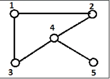
Consider the 5-bus system and its measurement configuration shown in fig. 2.
Fig. 2: 5-Bus Example System
First, form the binary connectivity matrix A. The entries ofA are
defined as follows:
(14)
Matrix A can be directly obtained from the bus admittance matrix by transforming its entries into binary form. Building the A matrix
for the 5-bus system of fig. 2 yields
(15)
The constraints for this case can be formed as:
(16)
The operator “+” serves as the logical “OR” and the use of 1 in the right hand side of the inequality ensures that at least one of the variables appearing in the sum will be non-zero.
The first constraint f1≥1 implies that at least one PMU must be placed at either of buses 1, 2 or 3 in order to make bus 1 observable.
So after solving the constraints for this 5 bus system the PMU installed at bus 2 and 4 can make the whole system observable.
Case 2: A system which has injection measurements along with PMUs.
In this paper few injection measurements are also placed along with the PMUs to make the system observable and also to minimize the number of PMUs used in case 1.
In order to do this the objective function is modified and the
effect of injection measurement is added to this function. For
an n-bus system, the modified PMU placement problem can be
formulated as follows:
(17)
where
X is a binary decision variable vector, whose entries are defined
as:
w is the cost of the PMU installed at bus i;
w’ is the cost of the injection measurement at bus i;
The cost of PMU is considered to be twice than the cost of injection measurement so the value of w is taken as 2 and the value of w’ is taken as 1.
f(X ) is a vector function, whose entries are non-zero if the corresponding bus voltage is solvable using the given measurement set and zero otherwise.
is a vector whose entries are all ones.
Constraint functions ensure full network observability while minimizing the total installation cost of the PMUs with injection measurement.
Consider the 5-bus system and its measurement configuration shown in fig. 2.
First, form the connectivity matrix A. The entries of A are defined
as follows:
Building the A matrix for the 5-bus system of fig. 2 yields
(18)
The constraints for this case can be formed as:
(19)
The operator “+” serves as the logical “OR” and the use of 1 in the right hand side of the inequality ensures that at least one of the variables appearing in the sum will be non-zero.
After solving the constraints for this 5 bus system the PMU installed at bus 4 and injection measurement at bus 1 can make the whole system observable.
Case 3: Placement strategy against loss of a single PMU or injection measurement.
So far it is assumed that those PMUs and injection measurement which are placed by the proposed method will function perfectly. But, they are prone to failure just like any other measuring device. In order to guard against such unexpected failures, the above placement strategy is extended to account for single PMU or injection measurement loss. In this study, this objective is achieved by choosing two independent sets, a primary set and a backup set, each of which can make the system observable on its own. If any PMU or injection measurement is lost, the other set of PMUs or injection measurement will guarantee the observability of the system.
V. Simulation Results
Simulations are carried out on the IEEE 14-bus and IEEE 30-bus
systems.Binary Integer programming problem is solved using the MATLAB for the PMU placement problem formulation.In addition a programwritten in MATLAB is used for state estimation including the measurements from PMUs.
A. PMU Placement
IEEE 14-bus and 30-bus systems used for simulation are shown in figure 3 and 4. Table 1 shows the results for 14-bus system without
considering any PMU or injection measurement loss and Table 2 shows the results for 14-bus system considering single PMU or
injection measurement loss. Table 3 shows the results for 30-bus
system without considering any PMU or injection measurement
loss and Table 4 shows the results for 30-bus system considering
single PMU or injection measurement loss.
Fig. 3: IEEE 14-Bus System
Fig. 4: IEEE 30-Bus System
Table 1: Results for 14-bus system without Any PMUor injection measurement loss
ONLY PMU PMU WITH INJECTIONS
NO. OF
PMU LOCATION(BUS) NO. OF PMU LOCATION (BUS)
4 2,6,7,9
3 2,6,9
NO. OF
INJECTION LOCATION (BUS)
1 8
Table 2: Results for 14-bus system considering single PMU or Injection Measurement Loss
ONLY PMU(BACKUP) PMU WITH INJECTIONS(BACKUP) NO. OF
PMU LOCATION (BUS) NO. OF PMU LOCATION(BUS)
9 2,3,5,6,7,8,9,11,13
6 2,6,7,9,11,13
NO. OF
INJECTION LOCATION(BUS)
3 1,2,8
Table 3: Results for 30-bus system without Any PMU or injection
measurement loss
ONLY PMU PMU WITH INJECTIONS NO. OF
PMU LOCATION (BUS) NO. OF PMU LOCATION(BUS)
10 1,7,9,10,12,18,24,25,27,28
7 1,7,10,12,18,25,27 NO. OF
INJECTION LOCATION(BUS)
3 8,11,23
Table 4: Results for 30-bus system considering single PMU or
injection measurement loss ONLY
PMU(BACKUP) PMU WITH INJECTIONS(BACKUP) NO.
OF PMU
LOCATION
(BUS) NO. OF PMU LOCATION(BUS)
21
1,3,5,7,8,9,10,1 1,12,13,15,17,1
9,20,22,24,25,2
6,28,29,30
14 1,3,6,7,10,11,12,15,17,19,24,25,27,30 NO.OF
INJECTION LOCATION (BUS) 7 5,8,11,13,19,21,26
B. Cost Comparison in Both Cases
Since the cost of PMU is assumed to be twice of a injection measurement the cost function can be calculated as follows Cost = 2 × no. of PMUs + 1 × no. of injection measurement Let the cost of one Injection measurement device be x then the cost of PMU will be 2x.
Table 5 shows the comparison of cost for 14 bus system and Table
6 shows the comparison of cost for 30 bus system.
Table 5: Cost Comparison for 14-bus System COST
ONLY PMU 8x
PMU WITH INJECTIONS 7x
ONLY PMU (BACKUP) 18x
PMU WITH INJECTIONS
(BACKUP) 15x
Table 6: Cost Comparison for 30-bus System
COST
ONLY PMU 20x
PMU WITH INJECTIONS 17x
ONLY PMU (BACKUP) 42x
PMU WITH INJECTIONS
From these tables it can be seen that the cost of PMU with injection is less than using only PMU while the network is still observable. So the method to use PMU along with injection measurement is more economical than using only PMU.
C. Comparison of Estimation Accuracy in Both Cases
To investigate the accuracy of estimated variables, both the cases are tested with only PMUs and PMUs with injection measurement.
Two test systems (IEEE 14, IEEE 30 bus system) were tested with
2 different cases namely Only Minimum PMUs 1.
Minimum PMUs with Injection Measurements. 2.
Fig. 3 and Fig. 4 show the network diagrams for each system.
Each network has a voltage magnitude measurement connected to bus 1.
The setting of error standard deviations for power injection istaken as 0.01. A PMU has much smaller error deviation than other conventional measurements andis taken as 0.00001in this study. The different measurementparameters used for state estimation
of 14 bus system and 30 bus system are taken from [7] and [8]
respectively.
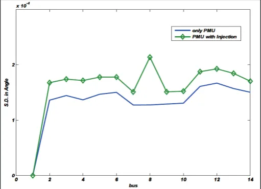
One of the ways of representing the level of state estimation accuracy is to refer the covariance of the estimated variables. The variances of variables are obtained from the inverse diagonal elements of gain matrix. The accuracy of two variables (voltage magnitude and voltage angle) is investigated separately. Fig. 5 and Fig. 6 show the accuracy of the estimated voltage magnitudes
of two systems IEEE 14 bus and IEEE 30 bus respectively. Fig.
7 andFig. 8 show the accuracy of the estimated voltage angles of
two systems IEEE 14 bus and IEEE 30 bus respectively.
Fig. 5: Accuracy of Voltage Estimates for Two Cases in IEEE-14 Bus System
Fig. 6: Accuracy of Voltage Estimates for Two Cases in IEEE-30
Bus System
Fig. 7: Accuracy of Voltage Angle Estimates for Two Cases in IEEE-14 Bus System
Fig. 8: Accuracy of Voltage Angle Estimates for Three Cases in
IEEE-30 Bus System
This clearly shows that the accuracy of the system having PMUs with injection measurement is less than the accuracy of system having only PMU, the difference is very small and can be neglected,thus the accuracy in both the cases can be taken as almost equal.
VI. Conclusion
In this paper, two types of placement techniques of PMU are discussed and the results are compared for state estimation, one which contains only PMUs and other which contains both PMUs and injection measurement. The optimum locations for placement of only PMUs and PMUs along with injection measurement are found for network observability with and without considering loss of singe PMU or injection measurement. Both the techniques
are tested on IEEE 14 bus and IEEE 30 bus systems. Binary
Integer Programming is done on MATLAB. The optimum locations obtained from the results are utilized for the calculation of cost of installation and covariance of the estimated variables.
Their benefits to state estimation are studied with respect to cost
References
[1] Bei Gou,“Generalized Integer Linear Programming Formulation for Optimal PMU Placement”, IEEE Transactions
on Power Systems, Vol. 23, No. 3, pp. 1099-1104, August
2008.
[2] B. Xu, A. Abur,“Observability Analysis and Measurement Placement for Systems with PMUs,” In Power Systems
Conference and Exposition, 2004. IEEE PES, pp. 943 – 946, Vol. 2, pp. 10-13 Oct. 2004.
[3] A.G. Phadke, J. S. Thorp, K. J. Karimi,“State Estimation
with Phasor Measurements”, IEEE Transactions on Power
Systems, Vol. 1, No. 1, pp. 233-241, February 1986.
[4] R. Zivanovic, C. Cairns,“Implementation of PMU Technology in State Estimation: An Overview”,IEEE Conferences, pp. 1006 - 1011, Vol. 2, 1996.
[5] DF A. G. Phadke,“Synchronized phasor measurements in power systems”, IEEE Computer Applications in Power,
Vol. 6, Issue 2, pp. 10-15, April 1993.
[6] D K. Zhu, L. Nordstrom,“Application and analysis of Optimum PMU Placement methods with application to State Estimation Accuracy”, Power & Energy Society General
Meeting, 2009. PES '09. IEEE 2009, pp. 1–7.
[7] [Online] Available: http://www.ee.washington.edu/research/
pstca/pf30/ieee30cdf.txt (accessed on June 2011)
[8] [Online] Available: http://www.ee.washington.edu/research/ pstca/pf14/ieee14cdf.txt (accessed on June 2011)
Kanika Jain received her B.Tech degree in Electrical and Electronics branch from Vidya College of Engineering, Meerut, U.P., India, in 2011, and will be completing M.Tech. degree in Power Systems from Amity University, Noida, India, in May 2016. She was an assistant professor, with Department of Electrical Engineering , in RadhaGovind Engineering college, APJ Kalam Technical University (formerly called Uttar Pradesh technical university ), in 2011
to 2013 respectively. She was an assistant professor, Neelkanth