JETIR1607026 Journal of Emerging Technologies and Innovative Research (JETIR) www.jetir.org 119
FINITE ELEMENT ANALYSIS AND OPTIMIZATION
OF EXTERNAL GEAR PUMP
1Prof. Kiran D.Kattimani, 2Prof R.K.Tavildar, 3Prof P.P.Kakamari 1,2,3 Asisstant professor,GIT Belgaum
ABSTRACT: In this paper, shell of external gear pump assembly is analyzed by using different materials to find application between aluminium and cast iron. The analysis is carried out by using Ansys software and based on the results, the shells are optimized which improved the overall performance of the pump. The shell deformation was measured with the optimized model and it was found to be within the working limits. This method of analysis, optimization also has an important significance to develop a whole new series of external gear pumps with different materials.
Keywords—gear pumps, finite element analysis, ANSYS, optimization
I.INTRODUCTION
Gear pump as a basic hydraulic pump, have the advantages of simple structure, low cost and long service life, is the factors which contribute to the widely used in mining mechanics, engineering mechanics, metallurgical equipment, construction mechanics, agricultural and forestry machinery etc. fields. In this dissertation, the subject of external gear-pump is the object of study, combined with CAD/CAE computer technology, finite element analysis and optimization to the existing gear-pump.
The external gear pumps are basically a housing containing two equal gearwheels, each of them held in housing. This mechanical simplicity is one big reason for their success, in addition to this the external gear pump is very light, small when it comes to volume, suited for hard conditions and can handle a wide range of different flow rates. At last, the external gear pump is one of the cheapest displacement machines on the market, which makes it a good competitor compared to other displacement machines.
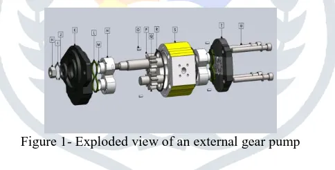
An exploded view of an external gear pump is shown in Fig. 1, from left to right it contains a sealing to prevent oil leakage (I), the sealing is mounted on the flange (K) followed by the case sealing (L). This is followed by an anti-extrusion ring and a seal which has the same shape as the seal in the following bushing (N), the anti-extrusion ring separates the suction area from the delivery area, this to avoid extrusion of the sealing parts. In general, the bushings are affecting the performance of the machine, external pressure peaks, cavitations and sealing of the volumes.
Figure 1- Exploded view of an external gear pump
II.WORKING OF GEAR PUMP
When the pump is operating the delivery pressure should be at maximum over the whole upper chamber and the lowest pressure inside the pump will be found at the suction side. The pressure should increase proportionally from the first tooth space volume until it reaches a maximum at the delivery section. This pressure increase causes the pump to feel radial loads which increasing from the suction side to the delivery side. The stresses due to the pressure differences are therefore highest at the delivery area of the pump. The fluid through the pump is transferred by the meshing process, which is caused by the sliding elements, i.e. rotation of gears inside the pump. The process is well described by Fig.2. The process begins with the fluid that enters the gear pump at the low-pressure region in the bottom; the gear teeth push the fluid around by rotation. These gears create an expanding volume on the suction side of the pump. The liquid that flows in the cavity will be trapped by the gears as they rotate. The liquid will continuously, travel around the interior of the casing, trapped in the volume created by the gear teeth and the casing. Thereby is the flow rate through the pump depended on the sum of volumes between the gear teeth and casing. An optimal design is therefore, according to a specific gear diameter, to choose as large number of teeth as possible. The fluid transport process ends when the meshing of the gears forces the liquid through the outlet under high pressure, this area is commonly called the discharge chamber.
JETIR1607026 Journal of Emerging Technologies and Innovative Research (JETIR) www.jetir.org 120
III.ESTABLISH THE SOLID MODEL
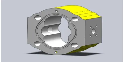
For modeling the external gear pump, Solid Works software was used to establish the solid model as shown in fig.3. The solid model of shell which was completed by Solid Works was saved as the format of *.sldprt, then it was imported into Ansys workbench. The linear elements of SOLID186 were chosen and used the smart way of ANSYS to mesh grids. The accuracy of Grade 2 was selected to mesh the shell.
Figure 3 - Solid model of shell of external gear pump
A typical process of ANSYS structural analysis involves three steps. The first step is to create finite element model, including the creation or import of geometry model, definition of cell types, and definition of unit physical constants, definition of material properties and the division of finite element mesh. The second step is to apply the loads, including constraints and load. The third step is to solve.
Materials used for shell of gear pump
Most common materials used for manufacturing on external gear pump shell are cast iron and aluminium. Analysis is performed using both the materials and then results are compared. Properties of these two materials are shown in Table 4.1
Table 4.2 - Material Properties
Cast Iron Aluminium Elastic Modulus 1.48x10¹¹ Pa 7x10¹⁰ Pa
Yield Stress 320 MPa 140 MPa
Poison’s ratio 0.25 0.34
Tensile strength 500 MPa 255 MPa
Density 7300 kg/m3 2760 kg/m3
Grey Cast Iron (Gray iron castings) is so called because of the colour of the fracture face. It contains 1.5-4.3% carbon and 0.3-5% silicon plus manganese, sulphur and phosphorus. It is brittle with low tensile strength, but is easy to cast.
Aluminium alloy 6061 is one of the most extensively used of the 6000 series aluminium alloys. It is a versatile heat treatable extruded alloy with medium to high strength capabilities. It contains 0.8-1.2 % magnesium, 0.4-0.8 % silicon, max 0.7 % iron, max 0.15 % titanium, max 0.15 % manganese, 0.05% others. The model was discretized using solid 186-element type. The discrete locations are referred as the grid or the mesh. The discretized model of the geometry is shown in Fig. 4
Figure 4– Finite element mesh of the shell
The finite element model of the shell of external gear pump was considered for two different materials, i.e. cast iron and aluminium. All constraints of three directions of UX, UY and UZ were exerted for 4 bolt holes of shell. The inner wall of high-pressure region of oil and the inner wall of the export channel of high-pressure oil were loaded with the pressure of 25 MPa, which can analog the working situation of the external gear pump under maximum load. Fig. 4.5 shows the boundary conditions applied on the shell of external gear pump. When the load and constraints were added, the appropriate command of ANSYS was selected to solve the shell.
IV.RESULTS:
An APDL code is used to check the structural safety of the problem. By the post-processor of ANSYS, the nodal plot of equivalent stress and
the nodal plot of resultant displacement in the case of 25 Pa were plotted.
JETIR1607026 Journal of Emerging Technologies and Innovative Research (JETIR) www.jetir.org 121
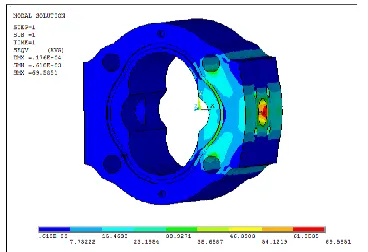
Figure 5 - The nodal plot of equivalent stress of shell of cast iron under 25 MPa
Figure 5 shows the deformation of the shell which becomes smaller and smaller from the center part of high-pressure area up and down both ends. The maximum deformation occurs in the center of high-pressure surface. The maximum deformation is 0.0108 mm, which can meet the requirement of the gear pump, as per manufacturing requirements and The American Society of Mechanical Engineers. 1996. ASME Y14.8M-1996, Castings and Forgings.
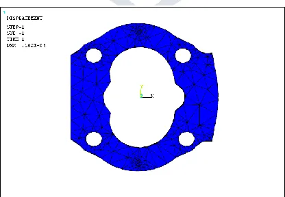
Figure 6- The nodal plot of resultant displacement of shell of cast iron under 25 MPa
The maximum equivalent stress of shell of aluminium under 25 MPa is 82MPa as shown in Fig. 5. It is close to the yield point of aluminium, which is 140MPa. So the safety factor of the shell is low. As shown in Fig. 6, the maximum deformation of shell of aluminum is 0.0244 mm, which is too large to make the gear pump work well.
Figure 7- The nodal plot of equivalent stress of shell of Aluminium under 25 MPa
JETIR1607026 Journal of Emerging Technologies and Innovative Research (JETIR) www.jetir.org 122
Therefore, the shell of aluminum cannot be used under the pressure of 25MPa. It means the maximum working pressure of shell of aluminum should be less than 25MPa. In order to know the maximum working pressure, different loads of 20MPa, 15MPa and 10MPa are applied on the shell. The equivalent stresses and the deformations under those loads are shown in the figures below.
Figure 9 - The nodal plot of equivalent stress of shell of Aluminium under 20 MPa
The maximum equivalent stress of shell of aluminium under 20 MPa is 69 MPa as shown in Fig. 7. It is close to the yield point of aluminium, which is 140MPa. So the safety factor of the shell is low, i.e. 3.69.
Figure 10 - The nodal plot of resultant displacement of shell of Aluminium under 20 MPa
Figure 10 shows the maximum deformation of shell of aluminium is 0.017mm under the load of 20MPa,which is large enough for the pump to work well.
From Fig. 11 and Fig. 12, maximum equivalent stress of aluminium under 15 MPa is 51MPa and the maximum deformation of shell of aluminum is small under the load of 15MPa. The Safety factor is 5.0. The shell can meet the manufacturing requirement.
Figure 11- The nodal plot of equivalent stress of shell of Aluminium under 15 Mpa
JETIR1607026 Journal of Emerging Technologies and Innovative Research (JETIR) www.jetir.org 123
In summary, the maximum safe working pressure of this shell of aluminum is 15MPa. Below this pressure, the shell has good performance.
V. OPTIMIZATION OF SHELLS
A series of optimizations was performed for shells by changing the size and structure, then the strength and stiffness of optimized shells were analyzed by ANSYS. According to the results provided in Ansys, we can reduce the thickness of the shell by 2.5~3mm, while increase the thickness of the plane of the exit of high-pressure oil. The optimized three-dimensional model is shown in Fig. 13
Figure 13 - Optimized model of shell of external gear pump
SolidWorks was used to measure the weight of original solid models and optimized solid models of shells. The optimized shell of cast iron is 1.189Kg lighter than the original shell of cast iron and the optimized shell of aluminum is 0.200Kg lighter than the original shell. The weight of the optimized shells of two different materials both decreased by 7.4% than the original ones.
The optimized shells of two kinds of materials were meshed by ANSYS, and then the different pressures were loaded to solve them. The nodal plot of equivalent stress and the nodal plot of resultant displacement in the case of 25MPa of the optimized shell of cast iron are shown in Fig. 6.2 and Fig. 6.3 respectively.
Figure 14 - The nodal plot of equivalent stress of optimized shell of cast iron under 25 MPa
Maximum equivalent stress of optimized shell of cast iron as shown in Fig. 14 generates in the exit of the export channel. Its value is 98.41 MPa, which is less than the value of yield point and tensile strength. The new safety factor is 5.08.
Figure 15 - The nodal plot of resultant displacement of optimized shell of cast iron under 25 MPa
JETIR1607026 Journal of Emerging Technologies and Innovative Research (JETIR) www.jetir.org 124
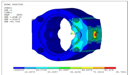
The maximum equivalent stress of shell of aluminium under 25 MPa is 90MPa as shown in Fig. 6.4. It is close to the yield point of aluminium, which is 140MPa. So the safety factor of the shell is low. As shown in Fig. 6.5, the maximum deformation of shell of aluminum is 0.022 mm, which is too large to make the gear pump work well.
Figure 16 - The nodal plot of equivalent stress of optimized shell of aluminium under 25 MPa
Figure 17 - The nodal plot of resultant displacement of optimized shell of aluminium under 25 MPa
The maximum equivalent stress and the maximum deformation of the optimized shell of aluminum when 20 MPa load is applied are shown in Fig. 18 and Fig. 19 respectively.
The maximum deformation of the optimized shell of aluminum under the pressure of 20MPa is too large, and the maximum equivalent stress is close to the yield point. So the shell cannot meet the working requirements
Figure 18 - The nodal plot of equivalent stress of optimized shell of aluminium under 20 MPa
Figure 19- The nodal plot of resultant displacement of optimized shell of aluminium under 20 MPa
JETIR1607026 Journal of Emerging Technologies and Innovative Research (JETIR) www.jetir.org 125
Figure 20- The nodal plot of equivalent stress of optimized shell of aluminium under 15 MPa
Figure 21 - The nodal plot of resultant displacement of optimized shell of aluminium under 15 MPa
Equivalent stress and resultant displacement of aluminium shell when 10 MPa load is applied is shown in Fig. 22 and Fig. 23 respectively.
Figure 22 - The nodal plot of equivalent stress of optimized shell of aluminium under 10 MPa
Figure 23 - The nodal plot of resultant displacement of optimized shell of aluminium under 10 MPa
JETIR1607026 Journal of Emerging Technologies and Innovative Research (JETIR) www.jetir.org 126
The maximum deformation under 15MPa is 0.0122mm, decreased by 0.005mm than the original shell of aluminum. The maximum deformation has a reduction of 3.9%, which makes important practical significance.
VI. CONCLUSION:
In this dissertation work, the shells of external gear pumps of different materials were analyzed by ANSYS software to find the different applications between shells of cast iron and shells of aluminum. It was found that the maximum operating pressure for aluminium shell was 15 MPa or less. The shells of cast iron and aluminium were optimized, to reduce the weight of the component and hence the manufacturing cost, which improved the overall performance of the gear pumps.
The optimized shell of cast iron is 1.189Kg lighter than the original shell of cast iron and the optimized shell of aluminum is 0.200Kg lighter than the original shell. The weight of the optimized shells of two different materials both decreased by 7.4% than the original ones. The strength of the shells changed very little, while the maximum deformation of cast iron and aluminum decreased by 9.44% and 10.16% respectively.
VII. BIBLIOGRAPHY
[1] H. Kim, Two-Dimensional CFD Analysis Of A Hydraulic Gear Pump, AC 2007-821, American Society for Engineering Education, 2007.
[2] H. Li, C. Yang, The Finite Element Analysis and Optimizations of Shells of Internal Gear Pumps Based on ANSYS, Proc. of IEEE, 2011, 978-1-4244-8452, pp 185-190.
[3] J. Magnusson, Numerical analysis of the lubricant gap in external gear pumps considering micro level surface features, Masters thesis, Chalmers University of Technology, Gothenburg, 2011.
[4] K. Huang, Kinematic flowrate characteristics of external spur gear pumps using an exact closed solution, Journal of Mechanism and Machine Theory, Elsevier (Science Direct), 2008, pp 1121-1131.
[5] S. Wang, H. Sakurai, The Optimal Desing in External Gear Pump and Motors, Journal on Transactions of Mechatronics, Vol 16, 2011, pp945-951.
[6] D. Parker, Positive Displacement Pumps-Performance and Application, Proceedings of 11th International Pump Users Symposium, Texas A & M university, 1994.