Abstract— Robotic rehabilitation has widely being used especially for upper limb impairment due to neurological disorder or accident. Research has shown that robotic training can also provide repetitive movement without therapist assistant. In this paper, we discussed about the problem in identifying the positions (x,y,z) of robot’s arm end effector when generating a circular motion that can vary depending on the vision based feedback of patient hand. The idea to generate circular path is by using point-to-point (PTP) method in Cartesian space. A parametric equation for circle was used to make robot generate circular motion in point-to-point. A camera is employed to obtain the centroid value (x,y) is used with the imposing of inverse kinematic to track the target in PTP. Robot simulation is done using VREP and the algorithm is developed using LUA. Based on the simulation evidence, it is shown that our approach can be effectively used to produce a circular motion with the uncertain speed of target based on the vision feedback with accuracy of 97%. Therefore, it shows that trajectory of vision based robot is adapted to generate circular path and tracking hand motion by varying the speed of target.
Index Term— Robotic Rehabilitation, Trajectory Generation
I. INTRODUCTION
There are many causes that lead to upper limb pain which make the patient unable to move their hand normally such as stroke diseases, sports injury and accident. Statistics has shown that 26.7% Malaysian suffer upper limb pain which causes by sports injuries, overuse of muscle arm, stroke disease and accidents [1].
In order to solve the problem, recent research have shown that robotic training is a considerably new technology that shows great potential for application in the field of neuro-rehabilitation as it has several advantages such as motivation, adaptability, data collection, and the ability to provide intensive individualized repetitive practice [2]. The research on robotic training has been gradually improved to provide rehabilitation exercise using various method such as using
game-based training [3], hand tracking [4],virtual curling task [5] and etc.
Generally, the main concern in robotic rehabilitation training is hand motion analysis. This is to show the robot is dependable to become a therapy assistant. For example, in [6] it shows the ability of robot to guide a rehabilitation patient to move their hand by drawing a figure-of-eight path. The results were analyzed based on the improvement of patient hand to perform drawing task that guide by robot from the beginning until the end of training session. The improvement of motor skill to perform the drawing task is due to repetitive training by assistive robot. Repetitive training using robotic rehabilitation has increased the upper limb motor performance such as accuracy and speed when performing voluntary task [7].
However, there is problem in hand rehabilitation exercise which that the patient is not consistent in doing their exercise due to lack of guidance especially a when doing a complex motion such as circular. An assistive robot is needed in order to guide, track and follow the patient hand accurately to avoid demotivation from stop doing the exercise. In order to track the circular motion accurately, a vision sensor is added to the robot to improve the reliability to assist the patient to ensure that the robot can guide the hand even though the hand speed is varying. Therefore, to ensure the accuracy of tracking and guiding hand, trajectory planning is important. In robotic, trajectory planning can be point-to-point (PTP) or predefined path [8].
In this paper, we discussed the problem of generating a point-to-point circular motion in Cartesian space (x,y,z) which involved the trajectory of robot to move from initial position to final position and in multidimensional space. The idea to generate circular path is by using point-to-point (PTP) method in Cartesian space create computational burden where if the number of point-to-point increases, the calculation will be more and time taken is longer. However, by increasing the number of point, it will improve the smoothness of circular path. To get the circular motion, a parametric equation of circle is used. Fig. 1 below shows the scenario of rehabilitation exercise using vision based robot for hand muscle therapy.
The Investigation of Circular Path Generation
and Hand Motion Tracking Problem Using
Vision Based Robot
1
Farah Amirah Rasid,
2Muhammad Fahmi Miskon,
3Muhammad Herman Jamaluddin,
4Mohd Bazli
Bahar,
5Quah Jit Shen
Center of Excellence in Robotic and Industrial Automation, Fakulti Kejuruteraan Elektrik, Universiti
Teknikal Malaysia Melaka, Hang Tuah Jaya,76100 Durian Tunggal, Melaka, Malaysia.
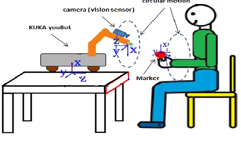
Fig. 1. Scenario of robotic hand rehabilitation
The present of vision sensor make the robot to move according to the vision feedback. The accuracy of tracking will decreases when the speed of target increases. In this project, by combining the equation of straight line and applying some image processing technique such as blob detection, centroid detection and using inverse kinematic it can tracking the image accurately.
In this paper, we present a robot that will be the assistant to do circular motion by getting the feedback from patient movement via camera to provide motivation to patient. The input data from vision sensor will make the algorithm to generate tracking and guiding trajectory in circular path.
II. LITERARTUREREVIEW
A. Visual based robot for rehabilitation applications The use of vision system coupled with the robotic arm can considerable improves the efficiency of robot manipulator to perform a complex task. In [9] an optimal based control is developed to perform manipulative actions with the use of vision sensor as guidance by identifying the forward and inverse kinematic to study the dynamic performance. Instead of using it for performing industrial task, the used of robotic arm with vision system is also applied in the robotic rehabilitation field.
There are some studies that have been conducted to improve the robotic rehabilitation technology based on vision to provide repetitive motion in order to improve upper limb motion exercise for people with upper limb problem due to stroke or any injury [10]. The overall architecture for this project is shown in Fig. 3 below. The patient hand motion will be traced by the vision sensor and match it motion with robot movement.
Fig. 3. Architecture of vision-based robot system for visual part
There are several related works that was done aiming to generate a robot motion based on visual feedback. Won-Kyung Song et. al [11], discussed about a robot with visual servoing will give autonomous capability to a rehabilitation robot to interact with human where the use of vision sensor allow the robot to get non-contact measurement of the environment. The proposed method using space variant is to achieve efficiency such as the high-speed and accurate visual processing in spite of influence of the environment as well as reduce the burden of a user of rehabilitations robot. There are also previous works related to an adaptive controller which are able to compensate with uncertain position of object using prediction method such as [12].
Ravipathi et. al [13], use image processing to design a vision based interface to instruct a humanoid robot doing some gestures. The project is interfacing the USB-UIRT (Universal Infrared Reciever and Transmitter) with humanoid toy robot (Robosapien) to obtain the output result which the robot will doing what it sees based on pattern matching. A pattern matching algorithm is developed to ensure the robot move according to the given gesture. There is other related work that use similar hand gesture recognition method to make robot generated trajectory and motion based on what they learned from the visual feedback such as shown in[14].
Benjamin Busam et al. [15], introduced a robust real-time marker based on tracking algorithm that provides the necessary information to reproduce the movement of the healthy arm with the weak arm. This system also allows controlling the robot with natural gesture. Non-contact human-computer and human-robot interaction is a vast field of research, however the main challenges lie in providing a robust and real-time recognition of the human desired motion [16].
All the related work focuses on generation of robot manipulator based on motion learning or recognition from visual feedback which the output is the robot will follow human desired motion. Therefore, in this project, it is not only generating a tracking and following motion based on the visual feedback but also to make robot generate its own trajectory based on the visual data to act as guidance in the rehabilitation purpose in order to prevent demotivation of patient.
B. Tracking and Generating Trajectory in Circular Path
As a rule, trajectory generation deals with problem trajectory generation deals with the problems specifying a trajectory with simple description and how to represent and generate trajectory in real time [17].
For tracking trajectory generation, the accuracy is important in order to provide a high performance of robotic arm system. The error for actual and planned trajectory can be minimized by a controller. In motion planning, control system should able to rectify the motion error while the environment variation is taken into account is crucially needed [18].
The use of robust controller will produce a high performance of tracking and following trajectory. In [19] a PD Computer
controller is used to produce high speed response and precision motion of robot dual link robotic arm system. The other method to obtain high accuracy is using PID controller such as in [20]. The control system is then improved to NCTF controller to produced high motion control performance and high robustness [21].
Even though these control method is designed due to the demand in industrial which require a precise motion of robot in performing task, in rehabilitation is also important for the robot manipulator to perform high accuracy in motion tracking so that in can give a good training exercise such as done by physiotherapist.
Nevertheless, this project is focused on the trajectory to track and follow hand as well as guiding the motion in circular path. Artificial intelligence is needed in order to produce a robust system. A continuous result for trajectory generation in circular motion is required in order to produce robust system.
Hence, there are several ways to generate a continuous trajectory of robot in circular motion. An accurate motion trajectory control is very important to avoid obstacles. Byoung-Ju Lee et.al [22], use a simple line and arc formula to generate trajectory of robot soccer in a circular motion. However, this method only gives accurate position control if the speed of robot is slow. This is due to the time delay limits its accuracy and it can be improved by further research on the precise control of the robot.
Ken-ichiYamada et al [23], generate a circular motion for mobile robot by using control law to make the robot determine the angle at the between two closest robot by itself. The researcher used a numerical simulation to generate the circular motion. The design parameters are based on the number of mobile robots, the radius and the required speed on the circle and gain value. The position and orientation are measured by a web camera and the controlled law for each mobile robot is computed by a central controller or PC. This method produced a smooth circular motion but have a high calculation burden.
In this project, it involves the movement of the end effector from the initial and final point in Cartesian space. There are more than two points needed to generate a circular path. Since this project is about rehabilitation of hand, the motion of path is free circular shape and no need a precise controlled path compare to [23]&[22]. Therefore point-to-point (PTP) is suitable to describe the robot motion. In PTP there is acceleration at the starting point and deceleration at the end point. To reduce the acceleration and deceleration profile, the number of PTP is increases and the time taken from one point to other will become short thus make the trajectory smooth. In control system point of view, by using PTP method, it is easy to observed the controller performance [24].
III. METHODOLOGY
A. Theoretical Concept
To move the robot manipulator in circular motion, different task must be solved. It must have good trajectory, considering some limitations and achieve high efficiency. Generally, there are some types of constraint for motion planning such as obstacle constraints, path constraints and mechanical constraints. Overall, in this paper, we discussed that 1. There
are no obstacles along the circle path, 2. 5DOF robot (Kuka youbot) with a camera attached on it will be used to do the circular motion using parametric equation of circle.
Imagine the scenario of this project as shown in Fig. 1. The visual feedback from the camera will became the input for the robot. Patient will hold a marker for the tracking purpose. The robot will do circular motion according to patient ability in following and guiding mode.
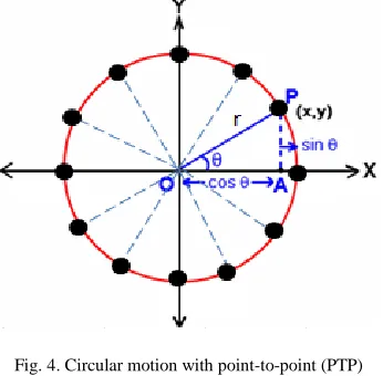
In order to generate trajectory in circular motion, a parametric equation of a circle is used. A parametric equation of circle is used to generate the point-to-point, P around the circular position in terms of coordinate (x, y). For the tracking part, the camera traced the centroid of the blob.
In this circular motion generation, there are several hand muscles that involved in the rehabilitation exercise. For the robot, there are several joints that involve and the value of theta for every joint is solved from the inverse kinematic.
Fig. 4. Circular motion with point-to-point (PTP)
Fig. 5. Centroid detection for tracking and following target in circular motion
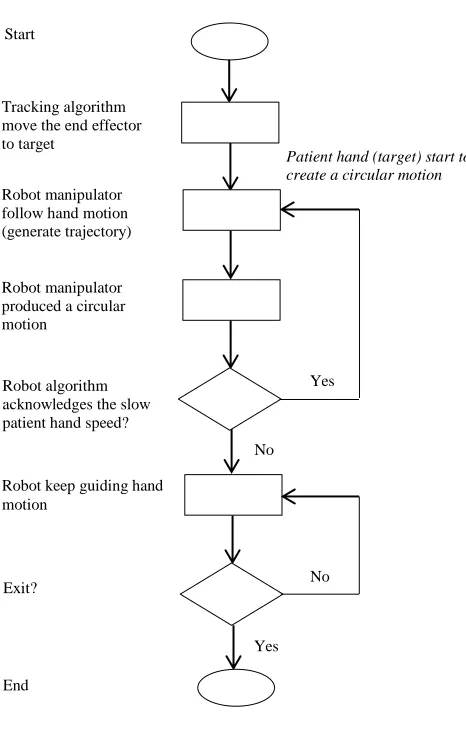
B. Flowchart for Circular Path Generation and Tracking Hand Motion
situation, the robot lead the therapy session and the patient need to train their hand according to the circular motion produced by robot manipulator.
Next, if the patient is unable to follow the robot arm motion, the robot will acknowledge it and it will try to track again the patient hand and follow the hand motion with slower speed to synchronise the motion. This tracking part is to prevent demotivation of patient from stop doing the exercise when they unable to catch up the robot guidance. The tracking and following mode is according to the speed of the hand motion. It means that if the patient motion speed changes the Kuka youBot arm position and speed will also change. The flowchart in Fig. 5 below shows the process for the overall project concept to enhance the understanding.
Fig. 5. Flowchart of project concept
C. Generating circular shape motion
In real case, the generation of circular motion produced by robot manipulator is not perfectly smooth. The smoothness improved when the number of point-to-point (PTP) increased. The algorithm is developed based on the equation of circular motion. The position, velocity and acceleration profile of end effector are determine to know the
performance of vision based robot in solving hand tracking problem for rehabilitation purpose.
D. Object Tracking Method
Since this project is hand tracking using visual based robot, the method used is simple blob detection where it is a method that aimed for a region an image that have different properties such as brightness or colour. These properties will be compared to the areas surrounding the selected region. In real case, patient grip a marker with bright colour for camera tracking purpose. The purpose of developing the algorithm is to extract the desired blob region (marker) and remove the unwanted layer. In the simulation using VREP, the comparison of actual and desired value of centroid using vision sensor is analysed to determine the accuracy of robot in tracking and following hand motion.
E. Image ratio
Image ratio is described as proportional relationship between width and height of an image. The initial step to obtain the image ratio is by determining the vision frame size. In this project, 256x256 resolution of vision sensor was used. The measurement and calculation of image ratio is done in terms of pixel size. To calibrate the size of image, we need to know the width and height of the target. By setting the image processing filter in VREP, it gives value for the width and height of the plane. The calculation of image size in pixel and image ratio is as below:
Image pixel = Width of object x resolution (1)
Frame size = 256 pixel x size of 1 pixel (cm) (2)
Note that for image processing, image calibration is not necessary because it is already calibrated and the camera does not have a fish eye effect plus the image is already flattened.
F. Angle of View from the Camera
Angle of view is angle to make the end effector move in specific position so that the target image will appear in the centre of vision sensor frame which is (0.5, 0.5) coordinate. To calculate the angle of view, we can use trigonometric ratio.
G. Positioning the End-Effector to Make the Target in the Centre of Vision Frame
In order to make the image at the centre of vision sensor when moving the end effector, some calculation is needed. The position of end effector of robot could also be adjusted according to world coordinate based on rotation and translation technique in 3D space in order to make the target appear at the centre of vision sensor frame. After the transformation matric, the target is referred to the world frame and it is moving in y-z axis. For example, consider that the original point is(x,y,z) and the desired position is (x + dx, y + dy, z + dz). The equation of straight line was used to make the end effector track and follow the target position.
Robot manipulator produced a circular motion
Tracking algorithm move the end effector to target
Start
Robot manipulator follow hand motion (generate trajectory)
Robot algorithm acknowledges the slow patient hand speed?
Yes
Robot keep guiding hand motion
Exit?
End
Patient hand (target) start to create a circular motion
y = mx + c (3)
m = 𝑦2−𝑦1
𝑥2−𝑥1
=
∆𝑦
∆𝑥
(4)
H. Method of Analysis
In order to validate parametric equation for circle to create a circular motion and to access the accuracy of robot in Cartesian space, the method to validate the result is by applying the percentage error and percentage accuracy formula for checking the deviation and the accuracy. Mean formula is used to calculate the values of image centroid to determine the accuracy of image detection as well as to prove the reliability of robot to track and follow human motion accurately. In circular motion simulation, the accuracy is calculated by determining the difference value of radius between the actual and desired circle.
I. Simulation Setup
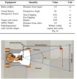
In order to proof that circular motion can be generated using PTP method, a simulation using VREP was done. The simulation is done to show the trajectory of robot end effector move from initial to final position in generating a circular motion and to access the accuracy of tracking and following target. By referring to the flowchart in Fig. 5, the simulation process is implemented using LUA & VREP robotic simulator. The overall simulation setup consist of these three main components which are Kuka youBot, visual sensor and target (blob). The workspace for the simulation was as shown in Figure 6.
Equipment Quantity Value Unit
Kuka youBot Distance from target 1.0 m Visual Sensor
(Perspective View)
Perspective Angle 30 ⁰
Near Clipping 0.01 m Far Clipping 1.0 m Target (red colour
sphere shape)
Radius 0.05 m Distance from robot 1.0 m Path(Segmented
with circular shape)
Radius Within visible region area (refer
Fig. 6)
m
Fig. 6. Simulation setup
Fig. 7. Simulation workspace
IV. RESULTS
A. Generation of Point-to-point circle
In this case, the position of robot and hand motion is in (y,z) plane because the trajectory is not planned on floor surface (x,y). Fig. 8 below shows the trajectory generation of robot when moving in point-to-point (PTP) in a part of circular motion. In trajectory generation, acceleration occurred when the robot start to move from the initial point and decelerate when reaching the final point. The acceleration and deceleration of Kuka youBot end effector motion in Fig.8 is high due to the number of PTP is less. This is the reason why the motion produced not really smooth. Meanwhile, the trajectory generation in Fig. 9 is smooth when the number of point is increased. The acceleration and deceleration profile is reduce due to the distance between point-to-point is reduced. Based on the results, increases in number of points have improved the smoothness of robot manipulator motion to generate a circular motion as well as increasing the computation time.
Fig. 8. Generation of PTP 0.00
0.05 0.10 0.15 0.20 0.25 0.30 0.35 0.40
0.10 0.30 0.37
z(
m)
y(m)
Fig. 9. Generation of PTP by increasing number of points
B. Image centre tracking based on Vision Algorithm
Blob detection method is used to make the robot follow the path by tracking the marker hold by patient (refer Fig. 1). Based on simulation results, vision sensor detects the blob image centre (x, y) to ensure that the robot constantly track the blob in circular path. The simulation is done for circular motion with different target speed.
The Fig. 10 below shows the values of image centre when the target is moving in a smooth circular motion. The desired centre value is (0.5, 0.5). The simulation is valid because the mean value shows that the image is always at range of centre value. The mean (y, z) is (0.511682291, 0.483396275) for smooth circular motion.
Based on the results, the image centre value is (0.3793, 0.3986) ≤ (y, z) ≤ (0.5906, 0.5795) for circular motion tracking which produce 96.67% accuracy. The error occurred in the maximum and minimum value is due to the variation of speed. It shows that the end effector is always trying to adjust its position so that the target always appears in centre of image frame.
Fig. 10. Tracking image centre read by vision sensor with varying target speed
C. Tracking and Following
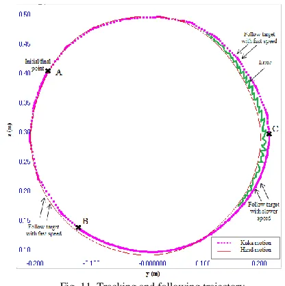
In this simulation, Kuka youBot is set to track and follow the motion of target which has uncertain speed. The position graph in Fig.10 shows the trajectory described by Kuka youBot and the actual trajectory that described by hand motion (target). The ‘x’ mark in Fig.10 indicates the initial and final point, and also the pit stop point that shows where the target speed change.
At point A to B and point C to A, the trajectory of Kuka youBot shows an apparent acceleration and deceleration at the point-to-point. This is due to the robot manipulator motion is limited by the inverse kinematic speed plus the motion of target is fast which is 0.07ms-1 from A to B and 0.05ms-1 from C to A.
The trajectory line becomes smooth when the speed of target is getting slower at 0.03ms-1 starting from point B until C. Based on the results, it shows that the trajectory generation of robot manipulator in via point is not necessarily passing through the exact point but the end effector only pass close the point.
Fig. 11. Tracking and following trajectory
Next, the positioning of robot motion has a little error especially when cornering as shown in shade region in circle in Fig. 11. This is due to jerk and acceleration of end effector when it tries to reach the position of target.
Nevertheless, the result shows that the tracking algorithm able to generate trajectory of Kuka youBot to track and follow target motion.
D. Guiding Circular Path Generation
In this simulation, Kuka youBot is able to generate its own circular motion. This is to show that the robot is not only track and follow a circular motion blindly but it has the ability to guide the circular motion. The result shows that by employing the parametric equation of circle, Kuka youBot able to
0.31 0.32 0.33 0.34 0.35 0.36 0.37 0.38
z(
m)
y (m)
KUKA motion
0.59064877
0.398548663 0.378255218
0.579518914
0 0.1 0.2 0.3 0.4 0.5 0.6 0.7
1 7 13 19 25 31 37 43 49 55 61 67 73 79 85 91 97
1
0
3
1
0
9
1
1
5
1
2
1
1
2
7
F
ra
me
V
al
u
e
Point-to-Point (PTP)
produce its own circular motion in PTP and hand motion is trying to follow the robot motion in circular path.
Fig. 12. Circular path generation
Therefore, the simulation shows that the parametric equation of circle allows Kuka youBot to generate its own circle to guide the patient hand. The speed of motion can be various depend on the ability of patient to do the motion.
E. Adaptive Trajectory Generation
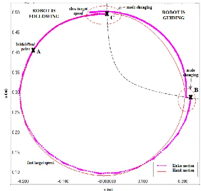
In this part, the simulation is done to proof that Kuka youBot can change mode of motion adaptively when uncertainty happen on the target speed. This simulation combined the tracking and guiding algorithm of Kuka youBot in circular motion generation for rehabilitation purpose.
Fig. 13 shows that Kuka youBot able to change its mode from following to guiding. By referring flow chart in Fig. 5, during start up at point A, target generated a circular motion with speed 0.05ms-1 and robot follow the motion. This tracking and following mode is shown in the Fig. 13 start at initial point A, until point B. At point B until point C, the speed of target is slow with speed 0.02ms-1 and at that point the robot manipulator change its mode from following to guiding by generating its own circular path and increasing its own speed. The radius of circular motion is generated based on the slow point of target which gained from the vision sensor data. Then at point C, when the target speed unable catch up the robot motion, robot manipulator autonomously change back to tracking and following mode to follow the target.
Fig. 13. Kuka motion versus hand motion
A small error occurred when the robot try to follow the position of target at point A to B. The fast target speed cause the limitation in joint motion due to tracking algorithm which concern to keep the target always in the centre of vision frame. The accuracy is high when target speed is slow. Based on the result, it shows that by employing the parametric equation of circle with tracking and following algorithm has enable Kuka youBot to generate an adaptive trajectory in circular path.
V. PERFORMANCEEVALUATION
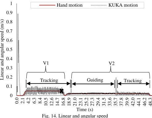
Fig. 14 below shows the speed of Kuka youBot arm versus speed of hand motion in the simulation runtime. Marker “V1” and “V2” in the graph show two different speed of target which are 0.05ms-1 and 0.02ms-1.
Initially, when the target starts to move, the speed is constant at 0.05ms-1 (V1). The target leads the robot motion until point ‘x’. Point ‘x’ indicates that at that point target unable to continuously produce the same speed in generating the circular motion. After point ‘x’, the target speed is reduced to 0.02ms-1 and switching mode takes place. When switching mode occurs, the speed of robot increased abruptly before becomes stable. The reason why it happens is because the speed of robot is set to be much faster than hand motion in order to lead and guide the hand after point ‘x’. This situation is also known as the transient response where the robot changes its motion from equilibrium state to a steady state.
Fig. 14. Linear and angular speed
Fig. 15 below shows the tracking and guiding performance of adaptive trajectory generation algorithm in terms of distance position. The maximum tracking error happens at point X until Y. Based on simulation, the error in positioning occurred due to the limitation of tracking algorithm and the imposing of inverse kinematic. This is because even we change the value of jerk and acceleration of joint, the error is still same and it is obviously occurred when cornering the circular motion. The maximum error is 0.03m or 3% respectively which produced accuracy of 97%. The error is reduced when the speed of target is slow as shown at starting point Z until final simulation. Therefore, the hypothesis of this simulation is the faster the speed of target the higher the error of position.
Besides that, oscillations of joints occurred at tracking motion from X to Y and from Z until final point. The oscillation is due to the tracking algorithm which concern on tracking the centre of target to ensure its position is at the centre of vision frame. The oscillation is more obvious from point X until Y. The behaviour of end effector rushing to capture the centroid of fast target speed causes it joints to oscillate. The oscillation reduced when speed of target is slow from point Z until final. In addition, the trajectory generation is based on tracking PTP in Cartesian space. Thereby the PTP also caused oscillation in the joint motion. In the guiding mode, the motion is smooth from point Y until is reach point Z
Fig. 15. Distance of Kuka youBot and hand motion
Based on the result, it is possible to make the errors close to zero, but it was at the cost of reducing the accuracy of tracking performance. It means that, if we adjust the image tracking part, the position of tracking and following is more accurate but the target image will not display in the centre of vision frame.
Therefore, we summarized that our results shows the dependability of vision based robot to perform therapy exercise. The reason is the simulation results shows that the robot is not just blindly follow the target, but it also able to act as guidance without attached with the patient hand. In contrast, the result of others work [3-5] only enable robot to perform guiding or following motion in separate manner. In relation with [7], our simulation result shows the accuracy to track and the ability guide hand motion may help speeding up upper limb recovery.
VI. CONCLUSION
In this paper, we have presented a point-to-point (PTP) circular motion method by using a parametric circle equation to prove that a vision based robot able to follow and guide hand motion in rehabilitation application. The smoothness of circular shape can be improved by increasing the number of via points but the computation time also increases. By using the blob detection and imposing the inverse kinematic, the robot achieved high accuracy when doing hand tracking. The motion tracking based on blob detection achieved 96.67% precision and it shows an acceptable reliability under the variation of hand motion speed. In terms of position, the accuracy is also 97% with error 3%. Therefore, the adaptive trajectory generation of a vision based robot is valid for circular hand tracking problem in terms of variation of speed.
For future work, this approach can be extended by develop other types of motions that required for rehabilitation training. Not only that, this work can be extended by developing a new algorithm to produce a better adaptive motion which can produced negotiation of motion between robot and patient requirements in terms of position and also add an algorithm of saving the result of rehabilitation of hand motion so that the
0 0.1 0.2 0.3 0.4 0.5 0.6 0.7 0.8 0.9 1 0
.0 2.1 4.2 6.3 8.4
1 0 .5 1 2 .6 1 4 .7 1 6 .8 1 8 .9 2 1 .0 2 3 .1 2 5 .2 2 7 .3 2 9 .4 3 1 .5 3 3 .6 3 5 .7 3 7 .8 3 9 .9 4 2 .0 4 4 .1 4 6 .2 4 8 .3 L in ea r an d a n g u la r sp ee d ( m/ s) Time (s)
Hand motion KUKA motion
Tracking V1 V2 Tracking Guiding 0 0.1 0.2 0.3 0.4 0.5 0.6 0
.0 2.0 4.0 6.0 8.0
1 0 .0 1 2 .0 1 4 .0 1 6 .0 1 8 .0 2 0 .0 2 2 .0 2 4 .0 2 6 .0 2 8 .0 3 0 .0 3 2 .0 3 4 .0 3 6 .0 3 8 .0 4 0 .0 4 2 .0 4 4 .0 4 6 .0 4 8 .0 z (m) Time (s)
Hand Motion KUKA Motion
oscillation
oscillation X
Y
robot can reproduced the circle motion based on the tracking data from patient hand motion.
ACKNOWLEDGMENT
The authors would like to thank for the support given to this research by Universiti Teknikal Malaysia Melaka (UTeM) (PJP/2018/FKE(1D)/S01600) and UTeM Zamalah scheme. This project was conducted in Centre of Excellence, Robotics and Industrial Automation (CERIA), in Faculty of Electrical Engineering, Universiti Teknikal Malaysia Melaka.
REFERENCES
[1] K. Veerapen, R. D. Wigley, and H. Valkenburg, “Musculoskeletal pain in Malaysia: A COPCORD survey,” J. Rheumatol., vol. 34, no. 1, pp. 207–213, 2007.
[2] P. S. Lum, C. G. Burgar, P. C. Shor, M. Majmundar, and M. Van der Loos, “Robot-assisted movement training compared with conventional therapy techniques for the rehabilitation of upper-limb motor function after stroke,” Arch. Phys. Med. Rehabil., vol. 83, no. 7, pp. 952–959, 2002.
[3] O. Unluhisarcikli, B. Weinberg, M. Sivak, A. Mirelman, P. Bonato, and C. Mavroidis, “A robotic hand rehabilitation system with interactive gaming using novel electro-rheological fluid based actuators,” Proc. - IEEE Int. Conf. Robot. Autom., pp. 1846–1851, 2010.
[4] G. Boato, N. Conci, M. Daldoss, F. G. B. De Natale, and N. Piotto, “Hand tracking and trajectory analysis for physical rehabilitation,”
2009 IEEE Int. Work. Multimed. Signal Process., pp. 1–6, 2009. [5] Y. Tanaka, “Robot-Aided Rehabilitation Methodology for
Enhancing Movement Smoothness by Using a Human Trajectory Generation Model With Task-Related Constraints,” J. Human-Robot Interact., vol. 4, no. 3, p. 101, 2015.
[6] E. Vergaro, M. Casadio, V. Squeri, P. Giannoni, P. Morasso, and V. Sanguineti, “Self-adaptive robot training of stroke survivors for continuous tracking movements.,” J. Neuroeng. Rehabil., vol. 7, p. 13, 2010.
[7] R. Colombo et al., “Robotic techniques for upper limb evaluation and rehabilitation of stroke patients,” IEEE Trans. Neural Syst. Rehabil. Eng., vol. 13, no. 3, pp. 311–324, 2005.
[8] S. A. Ali, K. A. M. Annuar, and M. F. Miskon, “Trajectory planning for exoskeleton robot by using cubic and quintic polynomial equation,” Int. J. Appl. Eng. Res., vol. 11, no. 13, pp. 7943–7946, 2016.
[9] M. H. Jamaluddin, M. A. Said, M. Sulaiman, and C. S. Horng, “Vision guided manipulator for optimal dynamic performance,”
SCOReD 2006 - Proc. 2006 4th Student Conf. Res. Dev. "Towards Enhancing Res. Excell. Reg., no. SCOReD, pp. 147–151, 2006. [10] N. Casteñeda and P. Saucedo, “GESTURE THERAPY A Low-Cost
Vision-Based System for Rehabilitation after Stroke,” no. Asa 2004, pp. 107–111, 2006.
[11] W.-K. Song, J.-S. Kim, and Z. Bien, “Visual servoing based on space variant vision for human-robot interaction in rehabilitation robots,” Eng. Med. Biol. Soc. 2000. Proc. 22nd Annu. Int. Conf. IEEE, vol. 4, pp. 2997–3000 vol.4, 2000.
[12] A. E. Hunt and A. C. Sanderson, “Vision-Based Predictive Robotic Tracking of a Moving Target,” no. January, 1982.
[13] D. Ravipati, P. Karreddi, and A. Patlola, “Real-time gesture recognition and robot control through blob tracking,” 2014 IEEE Students’ Conf. Electr. Electron. Comput. Sci. SCEECS 2014, pp. 0– 4, 2014.
[14] J. L. Raheja, R. Shyam, U. Kumar, and P. B. Prasad, “Real-time robotic hand control using hand gestures,” ICMLC 2010 - 2nd Int. Conf. Mach. Learn. Comput., pp. 12–16, 2010.
[15] B. Busam, M. Esposito, S. Che’Rose, N. Navab, and B. Frisch, “A Stereo Vision Approach for Cooperative Robotic Movement Therapy,” Proc. IEEE Int. Conf. Comput. Vis., vol. 2015–Febru, pp. 519–527, 2015.
[16] S. S. Rautaray and A. Agrawal, “Vision based hand gesture recognition for human computer interaction: a survey,” Artif. Intell. Rev., vol. 43, no. 1, pp. 1–2, 2012.
[17] M. F. Bin Miskon and M. B. A. J. Yusof, “Review of trajectory
generation of exoskeleton robots,” 2014 IEEE Int. Symp. Robot. Manuf. Autom. IEEE-ROMA2014, pp. 12–17, 2015.
[18] M. B. Bahar, M. F. Miskon, N. A. Bakar, F. Ali, and A. Z. Shukor, “STS motion control using humanoid robot,” Res. J. Appl. Sci. Eng. Technol., vol. 8, no. 1, pp. 95–108, 2014.
[19] S. P. Tee et al., “Tracking Control Performances a Dual - Limb Robotic Arm System,” no. 5, 2016.
[20] M. Tan, S. Chong, and T. Tang, “PID control of vertical pneumatic artificial muscle system,” Proc. Mech. Eng. Res. Day 2016, no. March, pp. 206–207, 2016.
[21] R. M. Nor and S. H. Chong, “Positioning control of a one mass rotary system using NCTF controller,” Proc. - 2013 IEEE Int. Conf. Control Syst. Comput. Eng. ICCSCE 2013, pp. 381–386, 2013. [22] B. Lee, S. Lee, and G. Park, “Trajectory generation and motion
tracking control for the robot soccer game,” Proc. 1999 IEEE/RSJ Int. Conf. Intell. Robot. Syst. Hum. Environ. Friendly Robot. with High Intell. Emot. Quotients (Cat. No.99CH36289), vol. 2, pp. 1149–1154, 1999.
[23] K. Yamada, N. Hara, and K. Konishi, “Circular motion generation for mobile robots using limit cycle systems — Application to a circular formation control,” SICE Annu. Conf. 2011, no. 2, pp. 342– 345, 2011.
[24] W.-K. Hee, S.-H. Chong, J.-E. Foo, and A. C. Amran, “Practical controller for positioning control of X-Y ballscrew mechanism,”