Analysis of Various RCC Lateral Force
Resisting Systems and their Comparison using
ETABS
Piyush Gupta
M.TechSchool of civil and chemical engineering VIT UNIVERSITY
Dr. Neeraja
ProfessorSchool of civil and chemical engineering VIT UNIVERSITY
Abstract- The tumor of population with a quicker frequency has imposed an unadorned effect on land which is resulting in its shortage and thereby swelling the land cost making it unaffordable for an average person. Due to this, the FAR (Floor Area Ratio) in big cities is increasing. This has enforced mankind to go for high rise structures. But, as the height of a structure increases, the effect of lateral forces increases with it. Lateral force resisting system plays an important role in the multistoried buildings which are situated in high seismic zones. Lateral force resisting system reduces the lateral forces acting during the earthquake and increases the stiffness of the structure. To make the structure earthquake resistant, the provision of lateral force resisting system is essential. There are various types of lateral force resisting systems like shear wall, braced core, shear core, outrigger with belt system, coupled shear wall, bracings etc. The scope of this paper is confined to RCC structures only. In this paper, the emphasis is given on the structures having lateral force resisting system. This study pointed to compare these systems and ranking all in terms of their efficiency. Static and dynamic analysis has been carried out and results have been compared. Cost evaluation has also been carried out. Several books and IS codes has been referred to obtain the results up to maximum accuracy.
Keywords: Braced core, Coupled shear wall, Outrigger with belt, Shear core, Shear wall, Etabs.
I. INTRODUCTION
forces used in this paper are braced core, coupled shear wall, outrigger with belt, shear core, shear wall, bracings at periphery. Proper study is carried out to find the effective size of components like, column, bracings etc. The most optimum position and parameters are found comparing the results given by Etabs. For example, outrigger is placed at three different positions, i.e., at top and one-fourth height of structure, at top and middle height of the structure and at top and three-fourth height of the structure. The most effective was evaluated based on analytical results. Then this result is compared with rest of the systems. After comparing all the results, these systems have been ranked according to terms of their effectiveness.
II. LITERATURE REVIEW
A number of researched have been introduced for different types of Lateral force resisting systems. The researches explain behavior of lateral systems. Alex Coull and Otto Lau.W.H (2011) studied the effect of outrigger system with belt at various positions of the building. Linear and nonlinear analysis are done. The paper concluded that the displacement is lowest when outrigger is provided at middle. Harries, et al (2004) presented the parametric study of coupled shear wall behavior. Positions of coupled shear wall are varied and span to depth ratio of coupling beam is also varied. The paper concluded that span to depth ratio of coupling beam should generally be 2.0 – 4.0. Murali Krishna and E Arunakanthi (2010) varied the position of shear wall and analysed the results in Etabs. Shear walls are usually provided along both length and width of buildings, Shear walls are like vertically-oriented wide beams that carry earthquake loads downwards to the foundation. Properly designed and detailed buildings with shear walls have shown very good performance in past earthquakes. Shear walls in high seismic regions require special detailing. However, in past earthquakes, even buildings with sufficient amount of walls that were not specially detailed for seismic performance. The paper concluded that shear wall is most effective at corners of the building. Esmaili et al. presented the effect of RC shear wall system on a 56 storey building. The paper showed the seismic behavior of shear wall.
III. OBJECTIVE
The main objectives of the present study are as follows:
1. Study on Linear static analysis of various lateral force resisting systems and comparing the results (displacement, storey drift and stiffness) with the conventional structure.
2. Study on Linear dynamic analysis (Response spectrum) of various lateral force resisting systems and comparing the results (displacement, storey drift and stiffness) with static results.
3. Evaluation of all systems used and their comparison. 4. Ranking all the systems in terms of effectiveness.
IV. METHODOLOGY
E-TABS software is used to develop 3D model and to carry out the analysis. The lateral loads to be applied on the buildings are based on the Indian standards. The methodology includes:
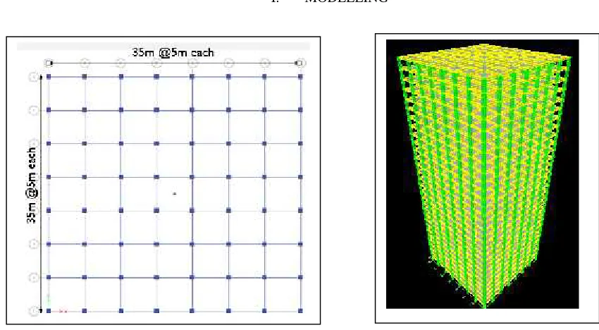
1. A 30 storey building is modelled in Etabs. The plan view is shown in Fig. 1 and 3-D view in Fig. 2. The details of the structure are shown in Table 1.
2. Six types of resisting systems were used i.e., braced core, shear core, shear wall, coupled shear wall, outrigger system with belt and bracing at periphery system.
3. The size of the bracings, columns and beams were calculated from SP-16, knowing the forces acting on them given by Etabs.
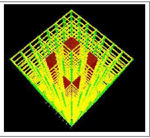
4. Coupled shear wall is positioned at 3 different positions and it came out to be most effective at position shown in Fig. 3
7. In bracing system, 4 different types of bracings are used at periphery i.e., eccentrically forward, eccentrically backward, V-type, inverted V-type. Inverted V-type came out to be most effective one (Fig. 6).
8. Static earthquake load and wind load by Force coefficient method is applied and results are obtained for load combination which produced the maximum effect i.e., 1.5 (DL + EQ). These results are compared.
9. Dynamic analysis is done to see the variation is results obtained by Static analysis. 10. Cost evaluation is done.
11. At last, systems are ranked according to their effectiveness.
Table 1
Contents Description
No of stories 30 (3m each)
Grade of concrete M 35
Size of beam 300mmx450mm
Size of column 700mmx700mm
Thickness of slab 150mm
Live load 4kN/m2(Commercial)
Floor finish 1.5kN/m2
Location Delhi
Terrain category 4
Structure class C
Zone factor (Z) 0.24
Importance factor (I) 1 Response reduction factor (R) 5
I. MODELLING
Fig. 3 Coupled shear wall at most effective position Fig. 4 Outrigger system with belt
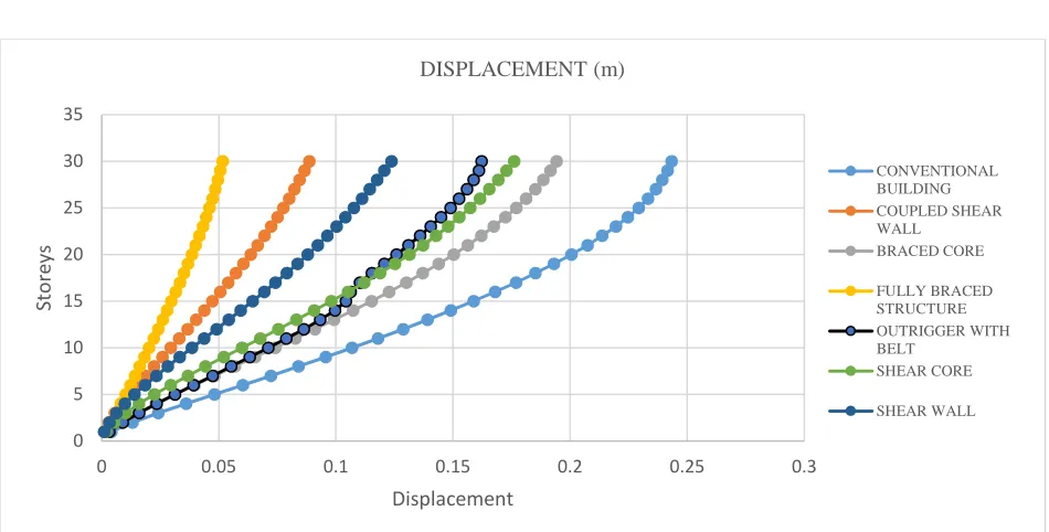
Displacement due to static analysis is shown in Fig. 7 and due to dynamic analysis is shown in Fig. 8. The results have been taken for the load combination which produced the maximum effect, i.e. 1.5 (DL + EQ). In the dynamic analysis, SRSS method has been used. The base shear obtained by dynamic analysis is scaled to base shear obtained by static analysis according to IS: 1893 (2002). In dynamic analysis, displacement from same load combination have been extracted. Displacement of the Inverted v-type bracing at periphery structure came out to be least among all and braced core to be the maximum. Coupled shear wall showed less displacement then shear wall.
0
5
10
15
20
25
30
35
0
0.1
0.2
0.3
0.4
S
to
re
y
s
Displacement
DISPLACEMENT (m)
CONVENTIONAL BUILDING COUPLED SHEAR WALL
BRACED CORE
FULLY BRACED STRUCTURE OUTRIGGER WITH BELT
SHEAR CORE
SHEAR WALL
0 5 10 15 20 25 30 35
0 0.05 0.1 0.15 0.2 0.25 0.3
St
ore
ys
Displacement
DISPLACEMENT (m)
CONVENTIONAL BUILDING COUPLED SHEAR WALL
BRACED CORE
FULLY BRACED STRUCTURE OUTRIGGER WITH BELT
SHEAR CORE
SHEAR WALL
Fig. 7 Static results
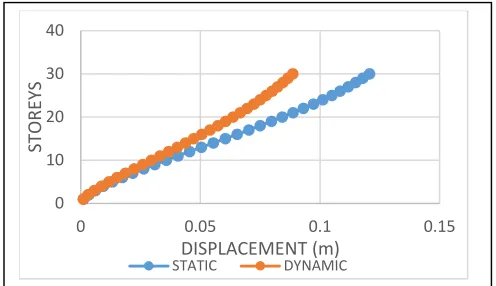
The results obtained from static analysis are compared with those obtained by dynamic analysis and a considerable fall in displacement is noticed in displacement in case of dynamic analysis. Fig. 9 shows results for coupled shear wall where the displacement dropped by 32mm at topmost storey. Fig. 10 shows results for braced core where displacement dropped by 58mm. Fig. 11 for bracing at periphery and drop noticed is 16mm. Similarly, Fig. 12, Fig. 13 and Fig. 14 shows results for outrigger, shear core and shear wall respectively and drop is 54mm, 60.5mm and 68.3mm. Highest drop in displacement have been observed for shear wall.
Fig. 10 Displacement for braced core
Fig. 13 Displacement for Shear core 0
10 20 30 40
0 0.05 0.1 0.15
ST
ORE
YS
DISPLACEMENT (m) STATIC DYNAMIC
Fig. 9 Displacement for Coupled shear wall
0 10 20 30 40
0 0.1 0.2 0.3
ST ORE YS DISPLCAMENT (m) STATIC DYNAMIC 0 10 20 30 40
0 0.02 0.04 0.06 0.08
ST
ORE
YS
DISPLACEMENT (m) STATIC DYNAMIC
Fig. 11 Displacement for Inverted V-type bracing
0 10 20 30 40
0 0.05 0.1 0.15 0.2 0.25
ST
ORE
YS
DISPLACEMENT (m) STATIC DYNAMIC
Fig. 12 Displacement for Outrigger system
0 10 20 30 40
0 0.05 0.1 0.15 0.2 0.25
ST ORE YS DISPLACEMENT (m) STATIC DYNAMIC 0 10 20 30 40
0 0.05 0.1 0.15 0.2 0.25
ST
ORE
YS
DISPLACEMENT (m) STATIC DYNAMIC
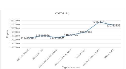
Percentage decrease in placement for all the systems is shown in TABLE 2. The ranking of all the structures have been done on this basis only. Cost evaluation is shown in Fig. 15. Volume of each component of structure is calculated and multiplied by the rate of M35 concrete. Percentage of steel is assumed in each building element like for column its 3%, which gives the quantity of steel used and cost is calculated. Cost of bricks and bracings is also calculated. Percentage increase in cost is shown in TABLE 3.
Table 2.
Building with coupled shear wall
Building with Braced core
Building with inverted V-type bracing
Building with outrigger and belt
Building with shear core
Building with shear wall
% decrease in Displacement
63.73% 19.37% 78.46% 28.3% 27.3% 43.3%
Table 3.
Building with coupled shear wall
Building with Braced core
Building with inverted V-type bracing
Building with outrigger and belt
Building with shear core
Building with shear wall
%increase in cost
3.48% 0.58% 0.1% 0.70% 1.304% 2.76%
117425589.2
118113966
117542009
118258776
118977965
121666516
120753855
115000000 116000000 117000000 118000000 119000000 120000000 121000000 122000000
R
upees
Type of structure COST (in Rs)
III. CONCLUSION
1. Outrigger is most effective when belt is provided at top and at middle position.
2. Shear wall is most effective when provided at the middle periphery. As shown in Fig. 5 3. Coupled shear wall is most effective at position shown in Fig. 3
4. When bracing is to be used at periphery, Inverted V-type is the most effective one.
5. Building with bracings at periphery came out to be the most effective one in terms of both effectiveness and cost.
6. Structures with shear wall are costlier then rest of the systems
7. Ranking of all systems in terms of their effectiveness in decreasing order: i. Building with Inverted V-type bracing at periphery
ii. Building with coupled shear wall iii. Building with shear wall
iv. Building with outrigger system with belt v. Building with shear core
vi. Building with braced core.
IV. REFERENCES
[1] Alex Coull and Otto Lau.W.H “Multi Outrigger Braced Structures”, Journal of Structural Engineering, ASCE, Vol. 115, No. 7, 2011. [2] Y. Chen, D. M. Mc Farland, Z. Wang, B. F. Spencer, J. R. L. A. Bergman “Analysis of tall buildings with outriggers”, Journal of structural
engineering, ASCE, 136(11), 2009.
[3] Harries, K.A., Moulton, J. D., and Clemson, R.L. (2004), “Parametric Study of Coupled Wall Behavior-Implications for the Design of Coupling Beams”, Journal of Structural Engineering, ASCE, 130(3), 480-488
[4] M Ashraf, Z.A. Siddiqui, M.A. Javed, “Configuration of Multi-storeyed building subjected to lateral forces”, Asian Journal of civil Engineering, vol. 9, no.5, pp. 525-535, 2008.
[5] A Murali Krishna, Dr. E Arunakanthi (2010) “Optimum Location of Different Shapes of Shear walls in Unsymmetrical High Rise Buildings”, American Journal of Engineering Research (AJER) vol 3.
[6] IS: 1893: 2002 “Indian Standard Code for Criteria for Earthquake Resistant Design of Structures”,Bureau of Indian Standards, New Delhi
[7] IS 875 (Part 2): 1987 “Indian Standard Code of Practice for design loads (other than earthquake) for buildings and structures–Live Loads”, Bureau of Indian Standards, New Delhi
[8] O. Esmaili et al. “Study of Structural RC Shear Wall System in a 56-Story RC Tall Building”, The 14th World Conference on Earthquake Engineering October 12-17, 2008, Beijing, China
[9] IS 875(Part 3): 1987 “Indian Standard Code of Practice for design loads (other than earthquake) for buildings and structures–Wind Loads”, Bureau of Indian Standards, New Delhi
[10] SP-16 “Design Aids for Reinforced Concrete”, Bureau of Indian Standards, New Delhi