ISSN: 2278-7461, ISBN: 2319-6491, www.ijeijournal.com
Volume 1, Issue 10 (November2012) PP: 19-28
Improvement of Dynamic Performance of Multi Area System
under Load Following Employing FACTS Devices
A. Suresh Babu
1, Ch.Saibabu
2, S.Sivanagaraju
21 Department of EEE, SSN Engineering College, Andhra Pradesh, India, 2
Department of EEE, J.N.T University, Kakinada, Andhra Pradesh, India
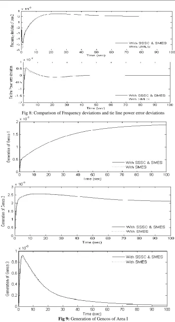
Abstract:––The enhancement of dynamic performance of load following based hydrothermal system under open market employing Static synchronous series compensator (SSSC) and Superconducting Magnetic Energy Storage (SMES) is presented in this paper. The SSSC and SMES have been modeled and an attempt has been made to incorporate these devices in the two area system thus improving the dynamic response of the system. The effect of these devices on the system is demonstrated with the help of computer simulations. A systematic method has also been demonstrated for the modeling of these components in the system. Computer simulations reveal that due to the presence of SSSC and SMES, the dynamic performance of the system in terms of settling time, overshoot and peak time is greatly improved than that of the system with SMES only.
Keywords:––Hydrothermal system, Open market system, Load Following, SMES, SSSC.
I.
INTRODUCTION
Large scale power systems are normally composed of control areas or regions representing coherent groups of generators. In a practically interconnected power system, the generation normally comprises of a mix of thermal, hydro, nuclear and gas power generation. However, owing to their high efficiency, nuclear plants are usually kept at base load close to their maximum output with no participation in the system AGC. Gas power generation is ideal for meeting the varying load demand. Gas plants are used to meet peak demands only. Thus the natural choice for AGC falls on either thermal or hydro units. Literature survey shows that most of earlier works in the area of AGC pertain to interconnected thermal systems and relatively lesser attention has been devoted to the AGC of interconnected hydro-thermal system involving thermal and hydro subsystem of widely different characteristics. Concordia and Kirchmayer [1] have studied the AGC of a hydro-thermal system considering non-reheat type thermal system neglecting generation rate constraints. Kothari, Kaul, Nanda [2] have investigated the AGC problem of a hydro-thermal system provided with integral type supplementary controllers. The model uses continuous mode strategy, where both system and controllers are assumed to work in the continuous mode.
On the other hand, the concept of utilizing power electronic devices for power system control has been widely accepted in the form of Flexible AC Transmission Systems (FACTS) which provide more flexibility in power system operation and control [3].An attempt was made to use battery energy storage system(BES) to improve the LFC[4]. The problems like low discharge rate, increased time required for power flow reversal and maintenance requirements have led to the evaluation of superconducting magnetic energy storage (SMES) for their applications as load frequency stabilizers[5-7]. Static synchronous series compensator (SSSC) in one of the important member of FACTS family which can be installed in series with the transmission lines [8]. With capability to change its reactance characteristic from capacitive to inductive, the SSSC is very effective in controlling power flow and application of SSSC for frequency regulation by placing it series with tie-line between interconnected two area power system with thermal units is proposed [9-10].
The reported works [11-13] further shows that, with the use of SMES in both the areas, frequency deviations in each area are effectively suppressed. In view of this the main objectives of the present work are:
1. To develop the two area simulink model of hydrothermal system under load following 2. To develop the model of SSSC and SMES
3. To compare the improvement of dynamic performance of the system with SMES only and SSSC with SMES. The rest of the paper is organized as follows: Section (2) focuses on dynamic mathematical model considered in this work. Section (3) emphasizes on the development of mathematical model of SMES. Section (4) describes the mathematical model of SSSC to be incorporated into the system. Section (5) demonstrates the results and discussions and some conclusions are presented in Section (6).
I. DYNAMICMATHEMATICALMODEL
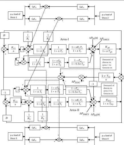
Fig. 1. Two Area load following Hydrothermal system with SSSC and SMES
II.
DESIGN
OF
SMES
Either frequency deviation or Area Control Error (ACE) can be used as the control signal to the SMES unit. In this work the frequency deviation of area 1 is employed as input to the SMES device. It can be seen from Figure 3 that the structure of SMES consists of gain block
K
SMES, time constantT
SMES and two stage phase compensation blocks having time constantsT
1,T
2,T
3,T
4 respectively. A performance index considered in this work to compare the performance ofproposed method is given by
t tie P f f J 0 2 12 2 2 2 1
Fig. 3. Schematic diagram of SMES applied to system
g T s 1 1 t T s 1 1 r r r T s T sK 1 1 1 1
R PD1(s)
+ - + -- 1 1 1 p p T s K s K11 B + + s T12 2 - + 3 1 R -1 2 2 1 P P T s K ) ( 2s PD + - + B s K12 -1 + + -
-p.u load of Disco 1
Cpf11
p.u load of Disco 2
+ + Cpf12
Cpf21 Cpf22
+ + 2 1 R -- a p f 1 a p f 1 +
- 1 1
1 T s
1 2
1 T s sTR w w T s T 5 . 0 1 1 s -a p f 1 a p f 1 +
p.u load of Disco 3
Cpf13
p.u load of Disco 4
+ + Cpf14
+
Cpf23 Cpf24
+ + 4 1 R Demand of discos in area 1 to Gencos in area 2
Demand of discos in area 2 to Gencos in area 1 + + - + + + + + Area-I Area-II 1 1 1 T s
III.
DESIGN
OF
SSSC
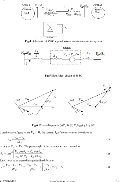
A SSSC employs self-commutated voltage-source switching converters to synthesize a three-phase voltage in quadrature with the line current, emulates an inductive or a capacitive reactance so as to influence the power flow in the transmission lines. The schematic of an SSSC, located in series with the tie-line between the interconnected areas, can be applied to stabilize the area frequency oscillations by high speed control of the tie-line power through interconnection as shown in Fig. 4. The equivalent circuit of the system can also be represented by a series connected voltage source
V
s along with a transformer leakage reactanceX
sas shown in Fig 5. The SSSC controllable parameter isV
s, which in fact represents the magnitude of injected voltage. Fig 6 represents the phasor diagram of the system taking into account the operating conditions of SSSC.
Fig 4: Schematic of SSSC applied to two- area interconnected system
Fig 5: Equivalent circuit of SSSC
Fig 6: Phasor diagram at (a)Vs=0; (b) Vs lagging I by 90 o
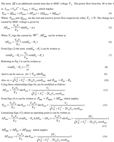
Based on the above figure when
V
s
0
, the currentI
oof the system can be written as
T n m o
jX
V
V
I
(1) WhereX
T
X
L
X
S. The phase angle of the current can be expressed as
n n m m
m m n n c
V V
V V
sin sin
cos cos
tan 1 (2) But Eqn (1) can be expressed in a generalized form as
I I
jX V jX
V V jX
V V V
I o
T s
T n m
T n s
m
The term
I
is an additional current term due to SSSC voltageV
s. The power flow from busm
to busn
can be written as Smn VmISmnoSmn which implies)
(
)
(
mno mn mno mnmn
mn
jQ
P
P
j
Q
Q
P
(4)Where
P
mnoandQ
mno are the real and reactive power flow respectively whenV
s
0
. The change in real power flow caused by SSSC voltage is given by
sin(
m
)
T s m mn
X
V
V
P
(5)When
V
slags the current by90
o,
P
mn can be written as
cos(
m c)
T s m mn
X
V
V
P
(6) From Eqn (2) the termcos(
m
c)
can be written as
cos(
)
cos(
n c)
m n c m
V
V
(7) Referring to Fig 3 it can be written as
xy
yw
c n
)
cos(
(8) And it can be seen asyw
V
msin
mn (9)Also
xy
V
m2
V
n2
2
V
mV
ncos
mn and
mn
m
n (10) Using these relationships Eqn (6) can be modified as followsmn n m n m s mn T n m mn V V V V V X V V P
cos 2 sin 22
(11)
From Eqn (4) it can be written as
P
mn
P
mno
P
mn which implies) cos 2 sin ( sin 2 2 mn n m n m s mn T n m mn T n m mn V V V V V X V V X V V P
(12)
Linearizing Eqn (12) about an operating point it can be written as
) cos 2 sin ( ) )( cos( 2 2 mn n m n m s mn T n m n m n m T n m mn V V V V V X V V X V V P
(13) SSSC tiemn
P
P
P
which implies) cos 2 sin ( 2 2 mn n m n m s mn T n m SSSC V V V V V X V V P
(14)
Based on Eqn (14) it can be observed that by varying the SSSC voltage
V
s, the power output of SSSC can be controlled which will in turn control the frequency and tie line deviations. The structure of SSSC to be incorporated in the two area system in order to reduce the frequency deviations is provided in Figure 5 shown below. The frequency deviation of area 1 can be seen as input to the SSSC device.. It can be seen from Fig 5 that the structure of SSSC consists of gain block
K
SSSC, time constantT
SSSC and two stage phase compensation blocks having time constantsT
1,T
2,T
3,T
4 respectively.Fig 7: Structure of SSSC 1 1 1 2 sT sT 1 3 1 4 sT sT SSSC
K
11sTSSSC
IV.
RESULTS
AND
DICUSSIONS
Simulation studies are performed to investigate the performance of the two-area hydrothermal system under deregulated Environment. Here in the two-area hydrothermal system three Gencos and two Discos are considered in each area. It is assumed in this work that one Genco in each area is under AGC only and the remaining Gencos participate in the bilateral contracts. It is assumed that there is 0.2% step load disturbance of each Disco, as a result of which the total step load disturbance in each area and accounts to 0.4% and each Genco participates in AGC as defined by following area participation factors (apfs):
apf
1=0.25,apf
2=0.25,apf
3=0.5,apf
4=0.25,apf
5=0.25,apf
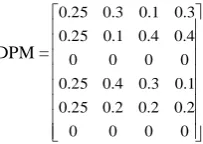
6=0.5 and the Discos contract with the Gencos as per the following Disco Participation MatrixDPM =
0 0 0 0
2 . 0 2 . 0 2 . 0 25 . 0
1 . 0 3 . 0 4 . 0 25 . 0
0 0 0 0
4 . 0 4 . 0 1 . 0 25 . 0
3 . 0 1 . 0 3 . 0 25 . 0
A nominal value of 0.5 is considered for the gain setting of integral controller in both the areas. Table 1 shows the comparison between the dynamic performance of the system with and without SMES. It can be observed that the system with SMES has better dynamic performance than the system without SMES. Contract violation case has also been considered in this work. In this case it is considered that Disco1 demands additional load of 0.3% after 30 sec and Disco4 in
area 2 demands additional load of 0.3% after 60 sec. It can be seen that the uncontracted power is supplied by the Gencos in the same area as that of the Disco which has demanded for additional power.
TABLE 1 COMPARISON OF SYSTEM PERFORMANCE WITH AND WITHOUT SMES
With SSSC & SMES
Area-I Area-II
Peak time
(sec) Overshoot
Settling Time (sec)
Peak time
(sec) Overshoot
Settling Time (sec)
1.77 0.003483 4.68 0.785 0.005696 3.9
With SMES 0.75 0.003856 4.345 0.825 0.004707 4.0
TABLE 2 COMPARISON OF PERFORMANCE INDEX VALUES
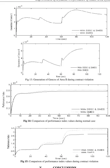
Performance Index Value (Base case) Performance Index Value (contract violation) With SSSC& SMES 7.801106 2.747105
With SMES 8.199106 3.332105
Fig 8: Comparison of Frequency deviations and tie line power error deviations
Fig 11: Comparison of Frequency deviations and tie line power error deviations during contract violation
Fig 13: Generation of Gencos of Area II during contract violation
Fig 14: Comparison of performance index values during normal case
Fig 15: Comparison of performance index values during contract violation
V.
CONCLUSIONS
A systematic method has been suggested for the design of a Superconducting Magnetic Energy Storage and SSSC for a multi area system under deregulated scenario. This paper has also investigated the performance of the system with SSSC and SMES, and with SMES only with respect to reduction of frequency deviations and tie line power deviations during a load change on a multi area system. The simulation results indeed show that the proposed method indeed successfully mitigates the frequency and tie line power deviations during a load change and also it can be seen that the performance index of the system with SSSC and SMES is less than the system only with SMES which indicates the superiority of the proposed method.
Appendix
2 1, p
p T
T = 20s; Kp1,Kp2= 120 Hz/p.u.Mw;
P
r1,
P
r2= 1200 Mw;T
t = 0.3s;T
g = 0.08s,T
w= 1s;s
T
r
5
,T
1
41
.
6
s
, 2T
=0.513s;R
1,
R
2= 2.4Hz/pu Mw; 12T
= 0.0866s;B
1,
B
2
0.4249p.u Mw/Hz; (b) CES data:T
1
0
.
279
;
T
2
0
.
026
;
T
3
0
.
411
;
T
4
0
.
1
;
K
CES
0
.
3
;
T
CES
0
.
0352
(c) SSSC data:
T
1
0
.
188
;
T
2
0
.
039
;
T
3
0
.
542
;
T
4
0
.
14
;
K
SSSC
0
.
292
;
T
SSSC
0
.
030
REFERENCES
1. C. Concordia and L.K.Kirchmayer, “Tie-Line Power and Frequency Control of Electric Power System - Part II”, AIEE Transaction, April 1954, Vol. 73, Part- 111-A, pp. 133-146.
2. M.L.Kothari, B.L.Kaul and J.Nanda, “Automatic Generation Control of Hydro-Thermal system” , journal of Institute of Engineers(India), Oct 1980, Vo1.61, pt EL2, , pp. 85-91.
3. Chun-Feng Lu, Chun-Chang Liu and Chi-Jui Wu. “Effect of battery energy storage system on load frequency control considering governor dead band and generation rate constraints” IEEE transactions on energy conversions Vol. 10 September1995, pp. 555- 561.
4. Kushik HJ, Kramer KG, Domnik H “ Battery energy storage – another option for load frequency control and instantaneous reserve” IEEE Trans Energy Conv 1986, 1(1), pp.46-51.
5. Ise T, Mitani Y, Tsuji K, “ Simultaneous active and reactive power control of superconducting magnetic energy storage to improve power system dynamic performance” IEEE Trans Energy Deliv 1986, 1, pp.143-150.
6. Tripathy SC, Balasubramanian R, Chandramohan Nair PS “ Effect of superconducting magnetic energy storage on automatic generation control considering governing deadband and boiler dynamics” IEEE Power Syst 1992, 7(3), pp. 1266-1273
7. Tripathy SC, Juengst KP “ Sampled data automatic generation control with superconducting magnetic energy storage in power systems” IEEE Trans Energy Conv 1997, 12(2), pp.187-191.
8. Hingorani NG, Gyugyi L, “ Understanding FACTS: concepts and technology of flexible AC transmission systems” New York, IEEE Press: 2000.
9. Gyugyi L, Schauder CD, Sen KK “Static synchronous series compensator: a solid-state approach to the series compensation of transmission lines” IEEE Trans Energy Deliv 1997, 12(1), pp.406-417.
10. Ngamroo I, Tippayachai J, Dechanupaprittha S “Robust decentralised frequency stabilisers design of Static synchronous series compensator by taking system uncertainties into consideration” Electrical power energy systems 2006, 28, pp. 513-524.
11. Banerjee S, Chatterjee JK, Tripathy SC. “Application of magnetic energy storage unit as continuous var controller” IEEE Trans Energy Conver 1990, 5 (1), pp.39–45.
12. Tripaty SC, , Kalantar M, Balasubramanian R “Dynamics and stability of wind and diesel turbine generators with superconducting magnetic energy storage unit on an isolated power system” IEEE Trans Energy Conver 1991;6 (4):579–85.
13. Banerjee S, Chatterjee JK, Tripathy SC “Application of magnetic energy storage unit as load frequency stabiliser. IEEE Trans Energy Conver 1990, 5 (1),pp. 46–51.
14. Jayath Kumar, Kah-Hoeng and Gerald Sheble, “AGC simulator for price based operation part- 1”, IEEE Transactions on Power Systems, vol.12,no.2, May 1997,pp. 527-532.
15. Jayant Kumar, Kah-Hoeng and Gerald Sheble, “AGC simulator for price based operation part- 2”, IEEE Transactions on Power Systems, Vol.12, no. 2, May1997, pp 533-538
16. Bjorn H. Bukken and Oves Grande “Automatic generation control in a deregulated environment” IEEE Transactions on Power Systems, vol. 13. No. 4 Nov 1998, pp. 1401-1406.
17. V. Donde, M. A. Pai and I. A. Hiskens, “Simulation and optimization in an AGC system after deregulation”, IEEE Trans. on Power systems, Vol. 16, No 3, Aug 2001, pp 481-489.
18. “Dynamic Models for steam and Hydro Turbines in Power system studies,” IEEE committee report. Transactions in Power Apparatus &Systems Vol.92,No.6,Nov./Dec.1973,pp.1904-915.
19. J. Nanda, Lalit Chandra Saikia, “Comparison of Performances of Several Types of Classical Controller in Automatic Generation Control for an Interconnected Multi-Area Thermal System”, Proceedings of 2008 Australasian Universities Power Engineering Conference, Paper No 22.