Abstract— Cascaded Thermal Energy Storage (CTES), a term that refers to a thermal energy storage system with multiple Phase Chance Materials (PCMs), has been enhanced by using metal foam. The present paper includes an experimental and numerical investigation for discharging process at different Heat Transfer Fluid (HTF) velocities, for three systems: single PCM; CTES, and CTES with metal foam at different porosities. The PCMs used are paraffin waxes with different melting temperatures. The main findings are: metal foam make the temperature distribution of PCM and the solidification process more regular and reduces the solidification time; the decreasing metal foam porosity leads to increased improvement; metal foam improves the total thermal power and average Nusselt number of HTF in CTES by rate of about (16.82% to 35.23%) and (24.25% to 42.03%) respectively, and there is a good agreement between the experimental and numerical results.
Index Term— Cascade thermal energy storage, Metal foam, Thermal performance, Discharging process.
I. INTRODUCTION
In recent years, energy consumption has expanded dramatically because of global economic development. As a result, there has also been an increase in greenhouse gases emission and environmental pollution. These factors have led to increased efforts to improve energy efficiency so as to reduce overall energy consumption. Thermal Energy Storage (TES) is an effective method of balancing energy demand and energy supply, allowing the energy system to be more stable and efficient [1].
The materials used in TES are referred to as Phase Change Materials (PCMs), and such PCMs have been studied in several different applications, including solar power plant [2, 3], energy saving buildings [4, 5], systems of waste heat recovery [6, 7], the cooling of electronic devices [8, 9], greenhouses [10, 11], and solar cookers [12, 13].
During charging, the PCMs absorb heat and their temperatures rise; thus, PCMs perform as sensible storage materials. Solid PCMs thus convert to liquid PCMs and the thermal energy is conveyed in this change. The PCMs absorb thermal energy at even small differences in temperatures and
store 5 to 14 times more energy than sensible storage materials [14]. The process reverses on release of heat during the discharge process and the PCM liquids completely revert into solids.
The high capacity of storage for small temperature differences is the major advantage of latent heat storage over storage of sensible heat; however, this does not mean that storage of latent heat cannot be beneficial at wider temperature differences. Nevertheless, it is reasonable to split a wide temperature difference into smaller divisions, each wrapped in a different PCM with an appropriate phase transition temperature [15]. A combination that uses multiple PCMs with various melting temperatures is called a Cascaded Thermal Energy Storage (CTES) system. Another objective for using CTES is that the charge and discharge time is limited in the most common functional case, and the heat must be released or stored rapidly. During the charging of storage systems with single PCMs, the heat transmits to the PCM from the heat transfer fluid (HTF) very rapidly. Thus, the temperature of the HTF decreases, and the temperature difference between the HTF and the PCM decreases, leading to reduced heat transfer at the storage end. Consequently, the PCM melts quickly at the part where the HTF enters the storage, but very slowly at the storage end where the HTF exits the storage. The problem is the same for discharging: the PCM at the storage ending might not be utilised in raising the HTF's temperature. This problem can be solved by creating a CTES [16].
Farid et al. [17, 18] experimentally and numerically constructed a model that included several cylindrical capsules filled with three PCMs with different melting points; the results showed enhancements in both charging and discharging. Gong and Mujumdar [19, 20] evolved a finite element model for a high-temperature thermal storage system of a slab [20] and a tube [19] that used five PCMs, finding a considerable improvement in heat transfer compared with the use of one PCM. Wang et al. [21] experimentally analysed the charging of a cylindrical thermal storage capsule containing multiple PCMs, discovering that the melting process was 15 to 25% faster than in systems containing one PCM. Shaikh and Lafdi [22] conducted a simulation to study the effects of utilising various arrangements of multiple PCMs slab configurations with various melting points, and they demonstrated significant enhancements in heat transfer.
Simulation and Testing of Thermal Performance
Enhancement for Cascade Thermal Energy
Storage System by Using Metal Foam
1
Hiba A. Hasan,
2Dr. Ihsan Y. Hussain
1Ph.D. Student., Mechanical Engineering Department, College of Engineering, University of Baghdad, [email protected]
2
Prof., Mechanical Engineering Department, College of Engineering, University of Baghdad,
Also, PCM have a very low thermal conductivity and for that reason, different enhancement methods are necessary to improve the thermal conductivity of PCM. Among these methods, the use of metal foam has been applied in different applications due to its numerous pores, which permits for a good fluidity of liquid PCM and wide specific contact surface area between ligament of metal foam and PCM, consequently the melting and solidification processes more uniform [23].
Vadwala [24] investigated experimentally and numerically the enhancement of the charging and discharging process of paraffin wax in TES by using Copper foam, the results showed that, thermal conductivity of wax increased by 16- 18 times and the time required to melt the wax reduced to 36%. Guo et al. [25] simulated numerically the effect of graphite foam on the charging process of PCM in shell-and-tube TES, the results indicated that graphite foam can improve heat transfer rate effectively. Tian and Zhao [26] enhanced theoretically the charging process in cascaded thermal energy storage (with three PCMs) by using metal foam. The main results were: CTES improved the heat exchange (up to 30%) compared to one PCM and further improved by the metal foam (by 2–7 times) according to metal foam properties, and the melting time was reduced in CTES by using metal foam (by 67-87%). The present paper thus aims to experimentally and numerically investigate the enhancement of discharging process of CTES by using metal foam.
II. PHYSICALPROBLEM
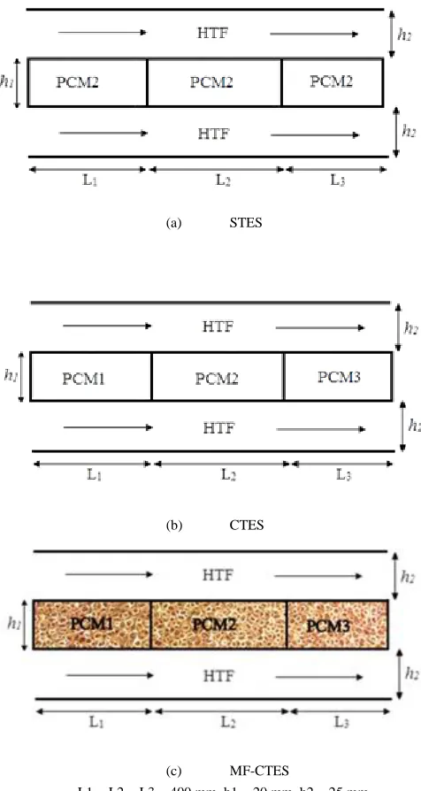
The present study compared three systems: Single stage Thermal Energy Storage (STES); CTES, and Metal Foam enhanced CTES (MF-CTES). A STES was formed with only PCM2 (Fig. 1(a)), CTES was constituted of three PCMs along the flow direction of HTF: PCM 1, 2, and 3 (Fig. 1(b)), and MF-CTES was constituted of the same PCMs in CTES with the same direction and the only difference was the presence of metal foam (Fig. 1(c)). The PCMs used were paraffin waxes and the HTF was air, and their thermo-physical properties are recorded in Table I. The melting temperature of PCM2 (in STES) has an intermediate value between PCMs 1 and 3, to give comparability between STES and CTES. The used HTF velocities were (1, 3, 5, 7 and 10 m/s). Copper foam with three different porosities (0.85, 0.90, and 0.95) and fixed pore density (30 PPI) have been used in the present work.
(a) STES
(b) CTES
(c) MF-CTES
TABLE I
THERMO-PHYSICAL PROPERTIES OF USED MATERIALS Materials
Properties
PCM1 PCM2 PCM3 Air
Melting temperature [K] 330 334 338 -
Solidus density [kg/m3] 841.32 852.14 860.77 1.225
Liquidusdensity [kg/m3] 757.25 766.11 770.53 -
Specific heat
[J/kg K] 2891 2900 2952 1006.43
Thermal conductivity
[W / m K] 0.241 0.265 0.322 0.0242
Dynamic viscosity [kg/m s] 0.0155 0.0121 0.0125 1.78*10-5
Thermal expansion coefficient [
1/K] 0.00031 0.000305 0.0003 -
Latent heat
[J / kg] 267670 270715 273760 -
Solidus temperature [K] 320 324 328 -
Liquidus temperature [K] 334 338 342 -
III. NUMERICALMODEL
A simulation of the melting and solidification processes of PCMs was applied using the enthalpy-porosity method [27]. In this method, there is no explicit tracking for the liquid-solid interface; instead, there is a mixed liquid-solid region, referred to as a mushy zone. This zone is modelled as a porous medium, with a porosity specified as equivalent to liquid fraction (β). The value of β is given by [28];
for T < Tsolidus
for Tliquidus < T< Tsolidus for T > Tliquidus (1)
where T is the local temperature. Thus, the velocity will be affected as follows:
in the liquid phase
in the mushy zone
in the solid phase (2)
where V is the superficial velocity and V1 is the actual velocity
[27]. A Boussinesq approximation is utilised to simulate the natural convection in the PCM, and thus the density of the PCM varies with temperature [29]:
(3) where ρ is the local density of the PCM, T0 and ρ0 are the
operating temperature and density, and γ is the thermal expansion coefficient. The metal foam is modelled as an isotropic homogeneous with a Darcy-Forchheimer law (modified Darcy law for high speed flow) because it behaves like a porous medium, and the flow of the liquid PCM in metal foam is assumed Newtonian, incompressible, with laminar flow. The continuity equation can therefore be illustrated as [30];
⃗ (4)
where t is the time. The pressure losses of flow produced by the existence of the solid PCM can be estimated using the source terms in the momentum equation [31]:
⃗⃗ ⃗ ⃗ ⃗ (5)
where μ is the viscosity of the PCM, p is the pressure, and the vector is a global source term given by the following form:
⃗ ⃗ √ ⃗ | ⃗ | (6)
damping factor of velocity through the solidification of the PCM, its value set to 105 kg/m3s [33]. The second term is the Boussinesq approximation, which is essential for modelling the natural convection in the liquid phase of the PCM. The vector is the gravitational acceleration, which is equal to 0 m/s2 in the x-direction and -9.81 m/s2 in the y-direction. The third term is the Darcy term and the last term is the Forchheimer (or inertia) term, metal foam resistances to the flow of PCM, where a and CF are the permeability and the inertial drag factor respectively, of the metal foam. They are calculated by the following [34];
( ) ( ) (7)
( ) (8)
where df, dp and ε are respectively the ligament diameter, the pore diameter and the porosity of the metal foam. They are linked to the other metal foam parameters by the following equations [34];
√ (
⁄ ) (9)
(10)
where ω is the pore density. The equilibrium thermal model is employed to simulate the heat transfer process of PCM in the metal foam, which treats the liquid PCM and the metal foam as they have the same temperature. The energy equation can be described as [14];
( ⃗ )
(11)
where L is the latent heat of the PCM, h is the sensible enthalpy and can be expressed as [35];
∫ (12)
where href is the enthalpy at the reference temperature Tref, and CP is the specific heat at a constant pressure. The effective thermal conductivity keff in equation (3.11) is calculated as the volume average of the conductivities of porous material and PCM, which are denoted by [25];
(13)
and are the thermal conductivities of metal foam and PCM, respectively.
The flow of HTF is assumed to be turbulent flow; to consider the turbulence effect, the ( ) model [36] was thus implemented in the numerical model. Two-dimensional numerical simulations were made with ANSYS Fluent. For the grid independence solution, three different grid densities were tested, with 21,600, 84,000, and 336,000 elements, respectively. The results showed that the 84,000 elements density was most suitable, because it represented the best compromise between solution accuracy and computational cost. A comparison with the work in [25] was undertaken for model validation: the same characteristics were used, and the two models gave similar results, demonstrating good agreement between them.
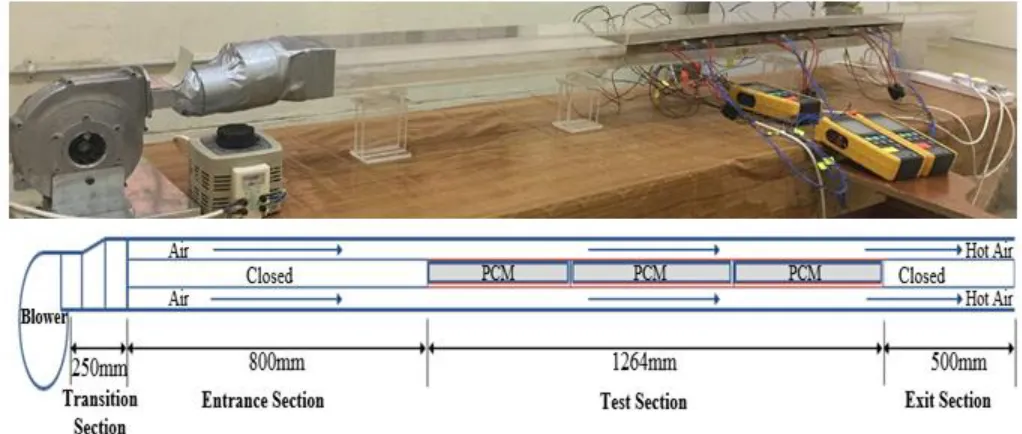
IV. EXPERIMANTALSETUP
Fig. 2. Experimental setup
V. RESULTSANDDISCUSSION
A. Experimental results
1) Behaviour of PCM temperature with time
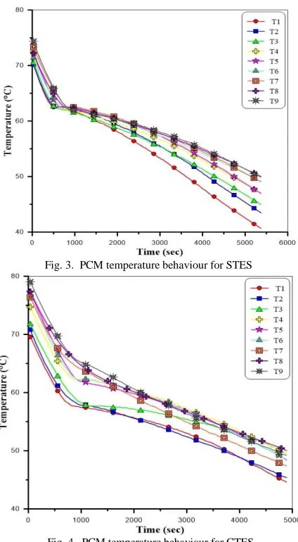
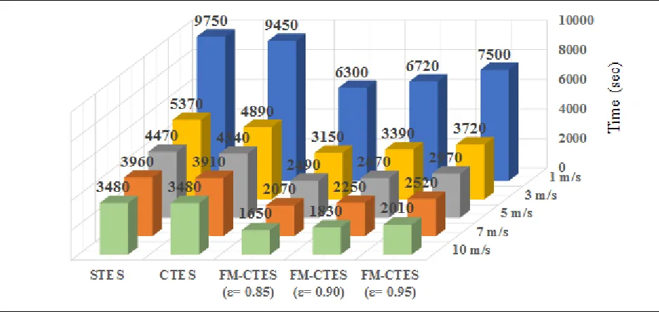
The solidification process for different HTF velocities is presented here. The temperature of PCMs was measured at nine points through PCM axial center line, three points in each box, shown in Figs. 3,4, and 5 for STES, CTES and MF-CTES (porosity 0.85) respectively, at HTF velocity of (3 m/s). It is very clear for any curve in the figures that the PCM temperature drops in turning from liquid to solid phase, at the beginning the heat is released from the PCM as a sensible heat. When the temperature of the PCM reaches the phase change temperature, the released heat is as latent heat where there is no decrease in temperature. After complete solidification, the release of heat is being as a sensible heat again. In Figure 3 for STES, the phase change of PCM occurs gradually from the first box to the last one with time difference between the boxes. While in CTES (Fig. 4), it is noticeable that the three boxes have a phase change at about the same time and reducing in solidification time. It is also noted that MF-CTES (Fig. 5) made the temperature distribution more regular and reducing in solidification time compared to CTES, that is due to the addition of copper foam which provides a large solid-to-fluid surface area and a high thermal conducting metallic phase, which allow for improvement the low thermal conductivity of PCM, thus reducing the thermal resistance of heat conduction and enhancement of heat transfer. The percentage of improvement in solidification time of MF-CTES over CTES at the five HTF velocities is shown in Fig. 6 for the three porosities used, it is obvious that decreasing porosity and increasing HTF velocity lead to increased improvement in time, where the porosity 0.85 at (10 m/s) gave the highest improvement that is (52.586%) compared with CTES at the same velocity. That is because a lower porosity indicates a lower volume fraction of PCM. At a fixed pore density, lower porosity denotes a higher
effective thermal conductivity and implies a larger fiber diameter or larger surface area of heat transfer. For Fig. 7 which is at (3m/s), it displays the influence of foam (0.85 porosity) on temperature distribution through PCM height in the box for CTES. Two points were taken on the same plane, the first is T1 located at the base of the box and the second is
T2 located at the middle of the PCM height, it can be seen
Fig. 3. PCM temperature behaviour for STES
Fig. 4. PCM temperature behaviour for CTES
Fig. 5. PCM temperature behaviour for MF-CTES
Fig. 6. The percentage of improvement in time of MF-CTES over CTES
(a) (b)
Fig. 8. Comparison between solidification time of performed experiments
2) Behavior of HTF Temperature
The data of the outlet HTF (air) temperature for one hour during heat release for the used systems are shown in Fig. 9, at (3 m/s) inlet air velocity. For all systems, at the beginning of the discharging process, the air outlet temperature increases sharply, and then followed change slower. The reason is that the initial increase is due to the sensible heat from the PCM, while later is caused by the phase change of PCM. Compare with STES system, the outlet air temperature increases in CTES system and further increase in MF-CTES system, this indicates that the stored heat is greater compared to STES. In MF-CTES, the outlet air temperature increases with reduced foam porosity where the highest temperature is at (0.85 porosity). Fig. 10 shows the distribution of air temperature along the passages on five points between the inlet and outlet for CTES system (at the beginning, middle, and end of each box) at 3m/s. It can be seen from the figure that the air temperature gradually increases from the inlet towards the outlet until it reaches its highest value at the outlet. The air temperature at the first two points after the inlet (T1 and T2, at
the middle and end of the first box respectively) is very close to the inlet temperature, because these points are close to the inlet so at this velocity the air temperature dose not rise much, while rising in the next points, as shown in Fig. 10. The influence of HTF velocity variation on outlet air temperature for CTES system is illustrated in Fig. 11 for one hour. The minimal used HTF velocity (v=1m/s) give the maximum outlet temperature and maximum difference between inlet and outlet temperatures, that is because with lower velocity, the flowing air has more time to flow over the PCM and that made it able to have more heat exchange. While the maximum used HTF velocity (v=10m/s) give the minimal outlet temperature and minimal difference between inlet and outlet temperatures, that
is due to lower time that the passing air exposed to PCMs.
Fig. 10. HTF Temperature Distribution for CTES along Air Passages
Fig. 11. The influence of HTF velocity variation on outlet temperature for CTES
3) Behavior of Thermal Power and Nusselt Number of
HTF
The relation between thermal power and Reynolds number of HTF is shown in Fig. 12 for CTES from each box. At the lowest value of Reynolds number, the power is almost identical in the first and third boxes and the highest value is in the second box, which indicate that the highest rise in HTF temperature is at the second box. While when Reynolds number is increased the thermal power from the first box is very few, because the first box is the closest to the entrance of the test section and increase the velocity of the HTF makes it pass very quickly on the first box and therefore very little time for heat exchange between HTF and PCM and so the temperature of the HTF rises very little only, this is illustrated above in Fig. 10. As for the second box, increasing Reynolds number to the second used value lead to increase the power which then be almost constant with the increase of Reynolds number. While for the third box, the increase in thermal power
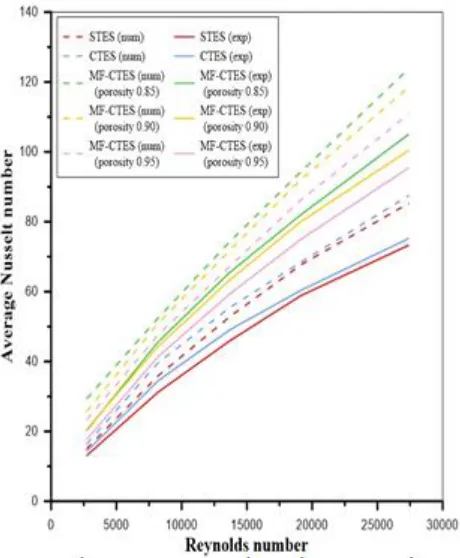
is gradual with the increase of Reynolds number, this because the highest rise in HTF temperature is at the third box when increasing Reynolds number. Fig. 13 shows the relation between local Nusselt and Reynolds numbers of HTF for CTES of each box. The behavior of Nusselt number of the three boxes is consistent with the behavior of thermal power in all boxes, because it also depends on the HTF temperature. Total thermal power which is the thermal power for overall test section is plotted as a function of Reynolds number in Fig. 14 for the used systems, increased Reynolds number leads to increased thermal power. The total thermal power for STES and CTES is almost approached and the greatest improvement of CTES over STES is at the second value of Reynolds number corresponding to the optimum HTF velocity (3 m/s). MF-CTES enhance the total thermal power in MF-CTES and as usual the decrease of metal foam porosity increases the enhancement. The rates of improvement between MF-CTES and CTES is about (16.82% to 35.23%). Fig. 15 shows the average Nusselt number for all tested cases, the Nusselt number varies linearly with Reynolds number. As in total thermal power, the highest improvement in average Nusselt number between STES and CTES is at the second used value of Reynolds number. The rates of improvement in average Nusselt number between MF-CTES and MF-CTES is about (24.25% to 42.03%).
Fig.12 Behavior of thermal power of HTF with respect to Reynolds number for CTES
Fig. 14. Behavior of total thermal power of HTF
Fig. 15. Behavior of average Nusselt number of HTF
B. Numerical Simulation Results
Fig. 16. Liquid fraction contours at HTF velocity of (3 m/s)
shows a comparison between the numerical and experimental results of average Nusselt number for STES, CTES, and MF-CTES (metal foam porosity of 0.85, 0.90, and 0.95) systems, a good agreement between them in the behavior of average Nusselt number with an increase in numerical values, and the carves become more linear compared to experimental curves.
Fig. 17. Average liquid fraction for CTES
Fig. 19. Comparison between the numerical and experimental average Nusselt number of HTF
VI. COMARISONANDVERIFICATION
To verify the results obtained for the present study, a comparison was made with the results achieved by previous studies. The present results of the temperature profile as a function of time for the solidification process of PCM in CTES systems and the effect of metal foam on temperature distribution shown in Fig. 7 agree with the results of Vadwala [24] shown in Fig. 20 for temperature results as a function of time while solidifying for both with and without metal foam. It is seen that with the use of metal foam it solidifies more uniformly than without metal foam and that uniformity is due to the effective thermal conductivity of foam-PCM system is significantly higher than that of PCM. As for the present results of the distribution of air temperature along air passages for CTES system, Fig. 10 is agree with the results of Farid et al. [17] shown in Fig. 21 during discharge process using three waxes each one in individual section.
Fig. 20. Solidification process of paraffin wax for both with and without metal foam [24]
Fig. 21. Measured and calculated air outlet temperature during heat dis-charge using three waxes [17]
VII. CONCLUSION
1.HTF velocity of (3m/s) was the optimal velocity for CTES, where it gave the largest reduction in solidification time and the greatest improvement in thermal power and Nusselt number of HTF for CTES over STES with experienced PCMs.
2.MF-CTES made the temperature distribution of PCM and the solidification process more regular and reduced the solidification time compared to CTES, and the decreasing porosity and increasing HTF velocity lead to increased improvement in time, where the porosity 0.85 at (10 m/s) gave the highest improvement that was (52.586%) compared with CTES at the same velocity.
3.The increased Reynolds number leads to increased the thermal power Nusselt number of HTF. The rates of improvement between MF-CTES and CTES was about (16.82% to 35.23%) and (24.25% to 42.03%) in total thermal power and average Nusselt number respectively.
with an increase in numerical values and the carves become more linear compared to experimental curves.
REFERENCES
[1] Mallow A, “Stable paraffin composites for latent Heat thermal storage systems”, M.Sc.Thesis (Georgia Institute of Technology) 2015.
[2] Michels Horst, and Robert Pitz-Paal, “Cascaded latent heat storage for parabolic trough solar power plants”, Solar Energy, Vol. 81, pp. 829–837(2007).
[3] Fernández I., Renedo C.J., Pérez S., Carcedo J., and Mañana M., “Advances in phase change materials for thermal solar power plants Quality”, International Conference on Renewable Energies and Power Quality, Las Palmas de Gran Canaria (Spain), (2011). [4] Tyagi V and Buddhi D, “PCM storage in building: a state of art”, J.
Renewable and Sustainable Energy Reviews (2007) vol 11 pp. 1146-1166.
[5] Lukić Predrag, Jasmina Tamburić, and Dragoslav Stojić, “ENERGY EFFICIENCY OF BUILDINGS WITH PHASE-CHANGE MATERIALS”, University of Niš, Faculty of Civil Engineering and Architecture, Serbia, Vol. 10, No 3, pp. 343 – 352, (2012).
[6] Alhamdo M, Theeb M and Golam A, “Finned double-tube PCM system as a waste heat storage”, IOP Conf. Series: Materials Science and Engineering (2015) vol 95 012033.
[7] Kiran C.Sai, and Meenakshi Reddy R., “Experimental Analysis of a Thermal Energy Storage System-Waste Heat Recovery”, International Journal of Innovative Research in Science, Engineering and Technology, Vol. 4, Issue 8, August, (2015). [8] Alshaer W, Nada S, Rady M, Barrio E and Sommier A, “thermal
management of electronic devices using carbon foam and PCM/nano-composite”, Int. J. Thermal Sciences (2015) vol 89 pp. 79-86.
[9] Kandasamy Ravi, Xiang-Qi Wang, and Arun S. Mujumdar, “Transient cooling of electronics using phase change material (PCM)-based heat sinks”, Applied Thermal Engineering, Vol. 28, pp. 1047–1057, (2008).
[10] Hassanien Reda Hassanien Emam, Ming Li, and Wei Dong Lin, “Advanced applications of solar energy in agricultural greenhouses”, Renewable and Sustainable Energy Reviews, Vol. 54 pp. 989-1001, (2016).
[11] Liu Y, Chen C, Guo H and Yue H, “An Application of Phase Change Technology in a Greenhouse” Proceedings of the 6th Int. Conf. for Enhanced Building Operations (Shenzhen: China) (2006) Vol II-2-5.
[12] kumar Naveen, Amit Budhiraja, and Sourav Rohilla, “FEASIBILITY OF A SOLAR COOKER IN OFF SUNSHINE HOURS USING PCM AS THE SOURCE OF HEAT”, Advances in Engineering: An International Journal (ADEIJ), Vol. 1, No.1, September (2016).
[13] Saxena A, Lath S and Tirth V, “Solar Cooking by Using PCM as a Thermal Heat Storage” MIT Int. J. Mechanical Eng. (2013) vol 3 pp. 91–95.
[14] Liu Z, Yao Y and Wu H, “Numerical phenomena in porous media: shell-and-tube type latent heat thermal energy storage”, J. Appl. Energy, 2013, vol. 112 pp. 1222–1232
[15] Nakhla D, “An enhanced latent heat thermal storage system using electrohydrodynamics (EHD)” M.Sc. Thesis (McMaster University Hamilton, Canada) 2013.
[16] Tian Y, “Heat transfer enhancement in phase change materials (PCMs) by metal foams and cascaded thermal energy storage”, Ph.D. Thesis (University of Warwick) 2012.
[17] Farid M and Kansawa A, “Thermal Performance of a Heat Storage Module Using PCM's With Different Melting Temperature: Experimental” J. Solar Energy Eng., (1989), vol 112 pp. 125-131. [18] Farid M and Kansawa, “A Thermal Performance of a Heat Storage
Module Using PCM's With Different Melting Temperature: Mathematical Modeling” J. Solar Energy Eng. (1990) vol 111 pp.152-157.
[19] Gong Z and Mujumdar A, “Cyclic heat transfer in a novel storage
unit of multiple phase change”, J. Appl. Thermal Eng. (1996) vol. 16 pp. 807-815.
[20] Gong Z and Mujumdar A, “Enhancement of energy charging-discharging rates in composite of different phase change materials” Int. J. Heat Mass Transfer (1996) vol. 39 pp. 725-733. [21] Wang J, Ouyang Y and Chen G, “Experimental study on charging
processes of a cylindrical heat storage capsule employing multiple-phase-change materials”, Int. J. Energy Res. (2001) vol. 25 pp. 439-447.
[22] Shaikh S and Lafdi K, “Effect of multiple phase change materials (PCMs) slab configurations on thermal energy storage”, J. Energy Conversion and Management (2006) vol. 47 pp.2103–2117. [23] Buonomo B, Ercole D, Manca O, and Nardini S, “Numerical
simulation of thermal energy storage with phase change materials in aluminum foam”, 12th REHVA World Congress 4 (2016).
[24] Vadwala H, “Thermal energy storage in copper foams filled with paraffin wax” M.SC. Thesis (University of Toronto) 2011. [25] Guo C, Zhang W and Wang D, “Numerical investigations of heat
transfer enhancement in a latent heat storage exchanger with paraffin/graphite foam” 10th Int. Conf. on Heat Transfer, Fluid Mechanics and Thermodynamics (Orlando: Florida) pp. 415-420 (2014).
[26] Tian Y and Zhao Y, “A review of solar collectors and thermal energy storage in solar thermal applications” Applied Energy (2013) vol. 104 pp. 538–55.
[27] Voller V and Prakash C, “A fixed grid numerical modeling methodology for convection-diffusion mushy region phase-change problems” Int. J. Heat Mass Transfer (1987) vol. 30 pp. 1709-1719. [28] Hesaraki A, “CFD Modeling of heat charging process in a
direct-contact container for mobilized thermal energy storage” Thesis (Malardalen University, Sweden) 2011.
[29] Buonomo B, Ercole D, Manca O and Nardini S, “Thermal Behaviors of Latent Thermal Energy Storage System with PCM and Aluminum Foam” Int. J. heat and technology, 2016, vol. 34, pp. S359-S364.
[30] Zhang P, Menga Z, Zhua H, Wangb Y, and Pengb S, “Experimental and numerical study of heat transfer characteristics of a paraffin/metal foam composite PCM” Appl. Energy, 2015, vol.75, pp. 3091 – 3097.
[31] Buonomo B, Ercole D, Manca O and Nardini S, “Numerical simulation of thermal energy storage phase change materials in aluminum foam” CLIMA - proceedings of the 12th REHVA World Congress (University of Naples II, Via Rome No. 29, 81031, Aversa (CE), Italy) vol 4, 2016.
[32] Nithyanandam K and Pitchumani R, “Computational Studies on Metal Foam and Heat Pipe Enhanced Latent Thermal Energy Storage”, J. Heat Transfer, 2014, vol. 136, pp. 051503-1
[33] Soibam J, “Numerical Investigation of a Phase Change Materials (PCM) heat exchanger”, M.SC. Thesis (Norwegian University of Science and Technology) 2017.
[34] Calmidi V, Mahajan L, “Forced Convection in High Porosity Metal Foams Journal of Heat Transfer, pp. 122 557,2000.
[35] Korawan D, Sudjito S, Widya W, and Denny W, “3D Numerical and Experimental Study on Paraffin Wax Melting in Thermal Storage for the Nozzle-and-Shell, Tube-and-Shell, and Reducer-and-Shell”, Models Modelling and Simulation in Engineering Volume Article ID 9590214, 9 pages, 2017.
[36] ANSYS FLUENT Theory Guide, 2013.
[37] Hiba A. Hasan and Ihsan Y. Hussain “Theoretical formulation and numerical simulation of thermal performance enhancements for cascade thermal energy storage systems”, 2nd
Int. Conf. on Eng. Sciences University of Kerbala, Col. of Eng. 26-27 March 2018.