JETIRCQ06058 Journal of Emerging Technologies and Innovative Research (JETIR) www.jetir.org 316
DYNAMIC ANALYSIS OF CABLE STAYED
BRIDGE UNDER MOVING LOAD FOR
DIFFERENT PYLON CONFIGURATION
1
Bhargav Chaudhari,
2Nihil Sorathia
1Student (M.Tech),2Assistant Professor, 1Structural Engineering,
1Parul Institute of Engineering and Technology, Vadodara,India
Abstract: Structural engineering has achieved a lot in the field of Bridge designing as it is most obvious in the world’s largest bridge spans, tallest structure etc. There are several types of bridges like Beam bridge, Arch bridge, Cantilever bridge and suspension bridge but In the recent years cable stayed bridges have received more attention than any other bridge mainly in the united-States, Japan and Europe as well as in East Asia countries due to their ability to cover large span Cable-stayed bridges have almost crossed 1100m (Russky Bridge, Russia). In India few of the cable Stayed bridges are constructed in which Bridges like Bandra-Worli sea link, Vidhyasagar Setu Bridge, Bharuch Cable Stayed Bridge and recently in surat one cable stayed bridge is constructed (2018) are the finest example of application of cable stayed bridge in India. In this study A cable stayed bridge will be modeled with proper technique from the guidance of different tutorial survey of Bridge design that is provided by software. A static moving load analysis is carried out and various response quantities like Bending moment, Shear force, Displacement, Torsion and axial force are represented. Then for carrying out parametric study of different shape of pylon and the different central span of the bridge, different models have been prepared in MIDAS civil. The Shape here taken for study are H shape and A shape pylon. The span taken for study varied from 480m, 950m, 1412m. All the length of the bridges are taken as per the length of the famous bridges in Gujarat like Elise bridge (Ahmedabad 480m), Nehru bridge (Ahmedabad 950m), and golden bridge (bharuch 1412m). Live load has been taken according to different Class of vehicle loadings were undertaken. The result of study is represented in graphical form for the various response quantities.
IndexTerms – Cable stayed bridge, Moving load analysis, Dynamic analysis, different shapes of pylon, MIDAS civil software.
I INTRODUCTION
Cable-stayed bridges have been well-known since the 18th century, but they have been widely used only since the first steel cable stayed bridge which was built in stromsund, Sweden in 1955. Reasons for the delayed use of these kinds of bridges are: the difficulties in their static and dynamic analysis, the geometric nonlinearities in their behavior, the absence of computational capabilities, the lack of high strength materials, construction techniques and quality control. While steel was the dominating structural material in the first German cable stayed bridges, prestressed and composite decks have increasingly been used in more recent projects. Many cable stayed bridges have now been built using increasingly slender girders with larger and larger spans. .
Cable-stayed bridges have become more and more popular in the Past decade in the United States, Japan and Europe as well as in South East Asia countries. This can be credited to quite a few advantages over suspension bridges associated high-strength steel, development of welding technology and growth in structural analysis and latest construction method which is very much in vogue.
J. C. Wilson explained Modeling of finite element of cable stayed bridge. Importance and procedure of pre-tensioning of cable is explained by D. Janjic. Importance of geometric nonlinear effects on the structural static analysis of bridges is explained by Freire.
II PROBLEM DISCREPTIONS
In Cable-stayed bridge having cables, different shapes of pylon are newly introduce part of bridge structure so it is Difficult to modeled and analyse the structures. So MIDAS civil is used as it is a well known software to design, modeling and analysis of cable stayed bridge. In this paper MIDAS civil software used for analysis and designed of structures based on static and dynamic finite element analysis. In this present paper cable stayed bridge having different span such as 480m (Elise bridge-Ahmedabad), 950m (Nehru bridge-Ahmedabad), 1412m (Golden bridge-Bharuch) is modeled with H and A pylon shapes.
III STRUCTURAL MODELLING
Fig.1.Geometry of cable stayed bridge Model (H shape pylon) generated in MIDAS civil.
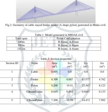
Fig.2. Geometry of cable stayed bridge model (A shape pylon) generated in Midas civil.
Table.1. Model generated in MIDAS civil Total span Pylon Configuration
480m H-frame, A-frame
950m H-frame, A-frame
1412m H-frame, A-frame
Table.2. Section properties
A.Deck
Box girder of concrete is shown in the Figure 2. It has to be exhibited such as to behave correctly in bending and torsion modeling is shown in Figure 1. A modeling approach is used in which a single central spine of linear elastic beam elements that has the definite bending and torsional stiffness of the deck.
Every spine element beams has a distance end to end connected by cables at each ends. At these nodes stiff links are used to connect with the cable in perpendicular direction to the beam element. This is done to accomplish the appropriate balance of the cables with respect to the center of inertia of the spine. Bridge deck section i.e. a box girder is modeled as a straight frame element.
Fig 3.Cross section of Girder
B.Pylon:
Hollow rectangular sections of steel are utilized for modelling the pylons.
Section ID Name Area
(m2)
Ixx (m4)
Iyy (m4)
Izz (m4)
1 Cable 0.005 0.0 0.0 0.0
2 Girder 0.309 0.007 0.1577 4.762
3 Pylon 9.200 19.51 25.567 8.123
4 CBeamGirder 0.049 0.003 0.0447 0.133
JETIRCQ06058 Journal of Emerging Technologies and Innovative Research (JETIR) www.jetir.org 318
C.Cable:
Cable is changed in to rod model, with it sectional area alone being considered. The bending rigidity of cable is ignored. Converted modulus of elasticity Eeq by the equation of H.J. Ernst is used to consider reduction of rigidity due to influence of cable sag.
Cable initial tension is provided in cables to minimize the bending- moment and deflection of the deck under dead loads. The method used to determine the initial cable tension is Simple beam method. The cable areas, pretensions and corresponding Modulus are different for different spans.
D.The boundary conditions
The boundary conditions of finite element model are always tough to model accurately the same as those of actual structures. The connection between the cables and the bridge deck has been considered to be pinned as cable shouldn’t take the rotational resistances.
E.Loading conditions
Moving load analysis in the present work is perform by IRC class AA, IRC class 70R and IRC class 40R vehicular live loads, The vehicles are generated and applied in the existing lanes following the guidelines from IRC: 6 (2000). Moving load generation in MIDAS civil. (a) Traffic lanes (b) Vehicle load in MIDAS civil (c) Moving load application the vehicles are applied to the lanes using the vehicle classes.
(1) Vehicle classes
The designer is often interested in the maximum and minimum response of the bridge to the most extreme of several types of vehicles rather than the result of the individual vehicles. The maximum and minimum force and displacement response quantities for a vehicle class will be the maximum and minimum ethics obtained for any individual vehicle in that class. Only one vehicle ever acts at a time.
All the vehicles are applied to the traffic lanes through the vehicle classes. If it is desired to apply an individual vehicle load, one has to define a vehicle class containing only that single vehicle.
(2) Moving load analysis cases
The last step in the description of the vehicle live loading is the application of the vehicle class to the traffic lanes. This is done by creating independent moving-load analysis cases. A moving load case is a type of analysis case. Unlike most other analysis cases you cannot apply load cases in a moving load case. Instead each moving load case consists of a set of assignments that specify how the classes are applied to the lanes .
IV ANALYSIS CASES AND COMBINATIONS
(1) Analysis cases
Dead- Consist of self weight + pretension
C1- Consist of class 40R applied in lane A and lane D C2- Consist of class 70R applied in lane B and lane C C3- consist of class AA applied in lane B and lane C C4- Consist of class A applied in all A to D lane
(2) Combination Dead+C1 Dead+C2 Dead+C3 Dead+C4 V RESULTS
JETIRCQ06058 Journal of Emerging Technologies and Innovative Research (JETIR) www.jetir.org 319
Chart 2: Shear force in pylon
Chart 4: Bending moment in pylon Chart 1: Shear force in girder
JETIRCQ06058 Journal of Emerging Technologies and Innovative Research (JETIR) www.jetir.org 320
VI CONCLUSION
(1) Girder forces
From the analysis result it can be seen that shear force value in girder are nearly equal in 480m span for both H shape and A shape pylon bridge girder but in 950m span shear force value of A shape pylon bridge girder is slightly decrease compare to H shape pylon bridge girder and for span 1412m Shear force value are very high compare to A shape pylon girder.
It can be seen that Shear force value are increasing for H shape pylon bridge girder as increasing span of the bridge and decreasing for A shape pylon bridge girder.
Bending moment of H shape pylon bridge girder and A shape pylon bridge girder are nearly equal in 480m span but in 950m span H shape pylon bridge girder moment is high compare to A shape pylon bridge girder moment. A shape pylon bridge girder moment is also increased but comparatively less than H shape pylon bridge girder.
H shape pylon bridge girder bending moment value of span 1412m are 22% higher compare to A shape pylon bridge girder.
Torsional moments of H shape pylon bridge girder are higher compare to A shape pylon bridge girder. Torsional Moments of 1412m span H shape pylon bridge girder are 58% higher compare to A shape pylon bridge girder.
It can be seen that axial force value of A shape pylon bridge girder is less compare to H shape pylon bridge girder for all the three span of cable stayed bridge.
(2) Pylon forces
Shear force value of A shape pylon of cable stayed bridge is less compare to H shape pylon of cable stayed bridge for all the three span of the bridge. For the 1412m span H shape pylon shear force value are very high compare to A shape pylon. Shear force value of H shape pylon and A shape pylon increased with increasing the span of the bridge but the increased value of H shape pylon of cable stayed bridge are very high compare to A shape pylon.
It can be seen that bending moment and Torsional moment of A shape pylon is very less compare to H shape pylon same as shear force.
Torsional moment of H shape pylon of 1412m span cable stayed bridge are 68% are higher compare to A shape pylon of 1412m span cable stayed bridge.
18% higher axial force value of A shape pylon compare to H shape pylon for 480m span, 16% less axial force value of H shape pylon compare to A shape for 950m span and 24% higher axial value of A shape pylon compare to H shape pylon. Hence, it can be said from the present work for the girder shear force, Bending moment, torsional moment and axial force value of both H and A shape pylon bridge girder increased with the increasing in the span of bridge. Shear force, torsional force and in axial force H shape pylon system have greater value but in bending moment for the span of 480m A shape pylon have 17% greater value Compare to H shape pylon bridge girder. Similarly in Pylon shear force, bending moment and Torsional moment H shape pylon get greater value but in Axial force 480m and 1412m A shape pylon get 18% and 24% higher value compare to A shape pylon. Thus from all the above discussion it is not easy to predict or clearly proved that which shape of pylon bridges are more advantageous.
REFERENCES
[1] Qing-Tian Su, Guo-Tao Yang, Fei Qin, Chong Wu, 2012, Investigation on the horizontal mechanical behavior of steel-concrete composite cable-pylon anchorage, Vol 72, PP 267–275.
[2] S.K. Hashemi, M.A. Bradford, H.R. Valipour 2017,, Dynamic response and performance of cable-stayed bridges under blast load: Effects of pylon geometry, Vol 137, PP 50–66.
[3] Vahid Akhoondzade-Noghabi, Khosrow Bargi , Decision-making of alternative pylon shapes of a benchmark cable-stayed bridge using seismic risk assessment 2016, 583-607.
[4] Salvador Ivorra, Dora Fotib, Francesco Paparella, F. Javier Baeza 2017, Dynamic load tests on the North-South axis cable-stayed bridge with a non-symmetric central pylon, PP 2967–2972.
[5] Lukasz Bednarski, Rafał Sieńko, Tomasz Howiacki,2015, Analysis of rheological phenomena in reinforced concrete crosssection of Rędziński Bridge pylon based on in situ measurements, PP 536 – 543.
[6] Freire A.M.S., Negra J.H.O., Lopes A.V. 2006. Geometrical nonlinearities on the static analysis of highly flexible steel cable-stayed bridges, PP 2128–2140.
[7] Wang P.H., Lin H.T., Tang T.Y , 2002, Study on nonlinear analysis of a highly redundant cable-stayed bridge, PP 165–182.
[8] Ma R., Chen X., Chen A.,2007, Effect of Cable Vibration on Aerostatic Response and Dynamics of a Long Span Cable-Stayed Bridge.
[9] Okamoto Y., Nakamura S, 2011, Static and seismic studies on steel/concrete hybrid towers for multi-span cable-stayed bridges, 203-210.