(UDC: 691.88:726.5)
Epistyles Connected with “I” Connectors Under Pure Shear
S. K. Kourkoulis*, E. D. Pasiou
National Technical University of Athens, School of Applied Mathematical and Physical
ciences, Department of Mech olytechnion Avenue, Theocaris Building,
57 73 Zografou, Athens, Hellas mail: [email protected] Corresponding author
bstract
n ambitious scientific project started in 1983 (and it is still in progress) aiming to the solution f a series of structural problems of the Parthenon Temple. One of them is the restoration of the amaged joins of the epistyles due to the corros e iron and their intense mechanical rain. In the frame of this effort, a parametric num undertaken, using the finite element method, in order to investigate the mechanical behaviour of the “I” shaped connectors and of the marble body surrounding them in case the epistyles are subjected to shear.
The models ed together
with one tita the blocks
and filled with suitable cementitious material (mortar). Synoptically the parameters studied incl
ors.
ring symbol of superiority of ancient culture and specifically of
S anics, 5 Heroes of P
1 E *
A
A o d st
ion of th
erical analysis was
simulate two identical prismatic blocks made from Dionysos marble join nium connector. The connector is embedded in a groove sculptured on
uded the boundary conditions, the existence or not of the mortar surrounding the connector and finally the existence or not of relieving space. The study indicated that the presence of both mortar and relieving space is of paramount importance. In addition in some cases the stress field developed may cause fracture of the marble blocks (either in the immediate vicinity of the interface of the two blocks or at the corners of the connector) rather than failure of the connector. Such a result is unacceptable according to the “Venice Chart” and supports existing approaches indicating the need for revision of the design of the connect
Keywords: Monuments, Dionysos marble, “I” connectors, Titanium, Shear, Finite Element Method
1. Introduction
The Parthenon Temple of the Acropolis of Athens was built in the 5th century BC by Iktinos and Kallikratis as an offer to goddess Athena. Phedias complemented it with masterly sculp-tures. It constitutes an endu
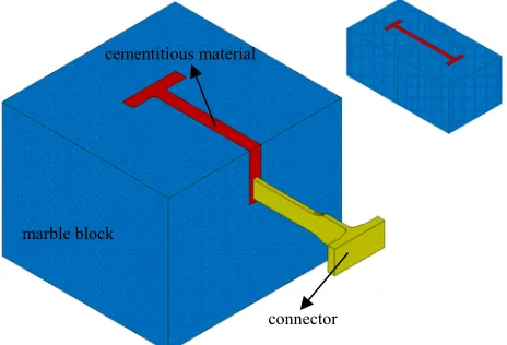
The Parthenon is a dry stone wall construction consisting of marble blocks joined by means of iron connectors (“I” shaped connectors and dowels) placed in grooves filled by ancient Greeks by molten lead. The marble blocks of each layer are joined together with “I’ shaped connectors (Fig. 1) while dowels join together marble blocks of sequential layers. The corrosion of iron and the intense mechanical strain led the connectors and/or the marble surrounding them to fracture. Therefore the restoration of the damaged joins was inevitably included in the restoration project of the Parthenon (Toumbakari, 2004, 2008, Vrouva, 2007).
ust fail. For the case of the structure studied here it is desired that under excessive loading the connectors are deformed absorbing
nd protecting thus the marble body (Zambas, 1994).
In general the connectors are subjected to shear and tension. Bending within the vertical
f yield’s or fracture’s origin. In a recent work Zambas (2004) studied the shear behaviour of dowels paying attention to the influence of the thickness of the dowel and the length of the relieving space. The specimens used consisted of three prismatic blocks of marble joined together with
cementitious material
marble bloc
Fig. 1. The connection of epistyles by means of “I” shaped connectors.
This specific problem is nowadays confronted by replacing the corroded iron connectors with new ones made from titanium (Korres & Bouras, 1983). The new connectors are embedded in groovessculptured on the marble blocks and filled with suitable cementitious material. The project is realized following the general principles of “Venice Chart” according to which the authentic marble must be protected and the new material m
strain energy a
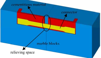
plane is not considered here since the parts of the members joined rest on the respective abacuses (Fig. 2). On the other hand bending within the horizontal plane, which could appear in case of seismic loading, is not included in the analysis, since the present work is devoted to static loading cases. The tensile behaviour of “I” shaped connectors and the shear behaviour of dowels has been already studied thoroughly (Zambas, 1994). On the contrary there is a lack of knowledge concerning the shear behaviour of the “I” connectors. However, many structural members of the monument could experience translation parallel to their neighbour ones and therefore it becomes obvious that pure shear of “I” connectors is one of the load cases that should be studied carefully.
The commonly used experimental methods for pure shear tests (shear boxes and “push-out” tests) cannot be used for the present study because they impose additional constraints to the specimens that affect the areas of interest, the failure mode and perhaps the location o
two dowels and mortar. The specimens were asymmetric due to the presence of the dowels. A transverse force was applied normally on the middle block and every effort was made to avoid torsion moments during loading. The other two marble blocks were fixed on the ground. Fracture of the marble was observed to all specimens in the form of a quarter of a cone. It was also concluded that the existence of relieving space enables the connectors to deform further absorbing additional strain energy.
of epistyles of the Parthenon temple connected
Fig. 2. A typical case with “I” connectors.
g of the reasons leading the connections of epistyles to failure.
beginning of the 20 century) and the absence of any mechanical or chemical decay effects on ontact with it. Finally, the use of titanium connectors was initially proposed also In this context the present paper is an attempt to investigate the behaviour of titanium “I” shaped connectors and of the marble surrounding them under pure shear. The study is carried out numerically using the finite element method. The results of the present numerical analysis will hopefully enrich and complete the existing data and contribute to a better understandin
2. Materials
The material used by the ancient Greeks for the erection of the Parthenon Temple of the Acropolis of Athens was Pentelic marble. It is an extremely durable white marble quarried from Mount Pentelicus in Attica. The ancient quarries are nowadays exhausted; therefore, the needs of the conservation and restoration program are covered almost exclusively with Dionysos marble due to its physical and mechanical similarity to the authentic marble. The cementitious material used by the scientists working for the restoration project on the Parthenon Temple as groove’s filling material was proposed by Skoulikidis (1971). His decision was based on the mechanical and chemical state of the oldcement (that of previous restoration attempts in the
th
the marble in c
2.1 Dionysos marble
Dionysos marble, of almost white colour, is composed by 98% of calcite, 0.5% of muscovite, 0.3% of sericite, 0.2% of quartz and 0.1% of chlorite. Its specific and apparent densities are 2730 kg/m3 and 2717 kg/m3 respectively and its absorption coefficient by weight is 0.11%. The
thermal ex t is 9x10⁶ /oC between 15 oC and 100 oC very low porosity
varies betw to 0.7% after the action of va natural weathering
and corrosiv 06).
Concer
arac-terized by t e web
and along t
ur-koulis, 1997 very
broad limit on
tests with c o of
the above a
ere-fore Diony
iso-tropy direc 77).
pansion coefficien . Its
een 0.3% in the virgin state
e agents (superficial porosity) (Tassogiannopoulos, 1986, Perdikatsis et al., 20rious ical behaviour Dionysos marble is an anisotropic material, ch
to the layers, alo he width of th ars to be orthotropi oulakis & Ko ies reported in literature vary between oroneos, 1979). A series of direct tension an iaxial compressi
icated that the mechanical propertie g the first tw ery similar to each other (Exadaktylo l., 2001a,b). Th onsidered as a transversely isotropic m l, with two an described adequately using five elastic consta hnitskii (19
Et [GPa] ν σf [MPa] σc [MPa]
ning its mechan
hree different anisotropy directions (parallel ng t he thickness of the web) and thus it appe
). The values of its mechanical propert c (Vard
s (Theocaris & K d un
ylindrical specimens ind nisotropy directions are v
s alon s et a
sos marble can be c ateria
tions (Table 1), nts Lek
Strong direction 84.5 0.26 10.8 80
Weak direction 50.0 0.11 5.3 55
Table 1. The mechanical properties of Dionysos marble under direct tension and uniaxial
the tension and in the compression regime and slightly bimodular, i.e. the elastic modulus in compression is espective one in tension. For the needs of the numerical analysis use
The
tics (Ko koulis et al., 2008). The specimens used were cylindrical (diameter over height ratio ~ ½) and the strains were measure ge rosettes. The failure mode observed was rather
brittle with significant or com n e specimen. In case of compression, the
mechanical characteristics obtained were: Modulus city E~15.5 GPa, Poisson’s ratio
ν~0.26, yield stress σy~10 MPa and compressi strength σu~35 MPa. From the series of
dia-metral compression tests only the tensile strength of the mortar σu~2 MPa was obtained. In the
present study, the mortar was considered as an isotropic material, obeying the constitutive law dictated by the above experimental study.
2.3 Titanium
Titanium has twice greater weight unit strength an steel and approximately the same Poisson’s
ratio and thermal expansion coeff characteristics protect the
struc-tural members of the monument from fracture due to differential lateral shrinkage and different-ial t
compression (Vardoulakis, Kourkoulis, 1997).
The above tests denoted also that Dionysos marble is slightly non-linear both in
about 15% higher than the r
was made of the actual stress-strain curve obtained by Vardoulakis & Kourkoulis (1997).
2.2 Cementitious material
cementitious material used today in the restoration project of the Parthenon Temple consists of 1 part white cement and 3 parts silica sand. A series of uniaxial- and diametral- (Brazilian test) compression tests were carried out in order to determine its mechanical characteris
ur
d using strain gau plete destructio of th
of elasti ve
th
icient as marble. The last two
amount of energy and bear high deformations before fracture (Zambas, 1994). The main mech-anical and physical properties of titanium are shown in Table 2. In the present study titanium was considered as an isotropic, linear elastic material due to its high strength compared to the respective one of marble and mortar.
Density (gr/cm3) 4.51
Modulus of elasticity (GPa) 105
Poisson’s ratio 0.32
Therm nsion coe -6 grad-1) 9
Thermal conductivity (cal/cm/grad/sec) 0.007
Hardness (HB) 130
Tensile strength (MPa) 420
Yield stress (MPa) 300
Ductility (%) 20÷22
al expa fficient (10
Table 2. The main physical and mechanical characteristics of titaniu ).
3. Numerical Analysis
In order to study the mechanical behaviour of both the connectors and the marble surrounding them when they are subjected to shear, a para tric numerical analysis was carried out using the finite element method and the commercially available software ANSYS 10.0.
3.1 umerical models
The geometrical c of a typical
epi-style of the Temp ea of 20x26 cm2
and length 25 cm, the groove’s depth is 7 cm and the connector’s length is 28.6 cm.
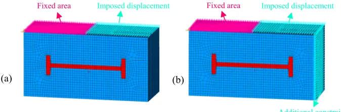
Four (4) models were constructed and synoptically the parameters studied included: (a) The boundary conditions (parameter 1), (b) the existence or not of the mortar surrounding the connector (parameter 2) and (c) the existence or not of relieving space (parameter 3), Fig. 3.
Fig. 3. The relieving space.
The first model, considered as the reference one (Model R), consists of all three materials. The groove has width 1.7 cm and it is filled with mortar (Figs. 4a, 5a). In Model AC an
ad-m (Zaad-mbas, 1994
me
The n
haracteristics of the numerical models matched exactly those le in a scale of 1:3. Each marble block has a cross section ar
cementitious material
connector
(a) (b)
ditional constraint is imposed at the block displaced in order to achieve parallel relative translation (Fig. 4b) which is indeed a realistic case as it is seen in Fig. 6. The next model (Model NM) is characterized by the absence of the mortar (Fig. 5b) in order to investigate its influence on the overall mechanical behaviour of the model. Finally, the last numerical model (Model RS1) studies the effect of the relieving space, in other words of the absence of mortar along a part (about 1 cm) of the connector from both sides of the interface between the two marble blocks (Fig. 3).
(b) (a)
Fig. 5. Change of parameter 2. (a) Model R; (b) Model NM.
Fig. 4. Change of parameter 1. (a) Model R; (b) Model AC. Fixed area Imposed displacement Fixed area Imposed displacement
Fig. 6. Parallel relative translation of two marble epistyles of the Parthenon temple. 3.2 Meshing
All numerical models were meshed in the same way. The element used is the SOLID185, com
or and the mort oduce
have hedron. Another meshing technique, t
-ar d he
or triangles respectively.
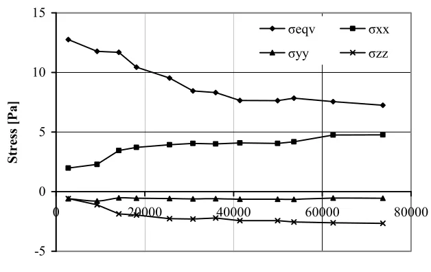
A series of preliminary “runs” were carried out in order to choose the optimum element size. The study of the stresses at characteristic points of all materials in relation to the number of elements indicated as sufficient a number of about 40 000 elements. In Fig. 7 the values of the various stress components developed at the central point of the central section of the con-nector are plotted vs. the number of elements indicating satisfactory convergence.
monly employed for 3-D modeling of solid structures. It is defined by orthotropic material pro-perties and eight nodes with three translational degrees of freedom each. It supports also plasti-city and large strain considerations, necessary for the needs of the present analysis.
A uniform meshing was chosen for the whole model. The titanium connect
were meshed using the Mapped Meshing Technique according to which the elements pr the shape of a brick, a wedge, a prism or a tetra
-5 0 5 10 15
Stress
[Pa]
0 20000 40000 60000 80000
Number of elements
σeqv σxx
σyy σzz
Fig. 7. The variation of the stress components at the central point of the central section of the connector vs. the number of elements.
3.3 M terial interfaces
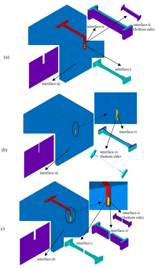
All material interfaces characterizing the sequence of materials were taken into account during the construction of the models. Analytically the interfaces considered are:
“titanium connector -mortar” (interface-i) w he shape of the connector since the cementitious material encloses the conn (a,c)
2 “mortar-marble” (interface-ii) which has the shape of the groove, Figs. 8(a,c) 3. “marble -marble” (interface-iii), Figs. 8 (a,c)
4. “titanium connector -marble” (in case the mortar is absent) (interface-iv), which has the shape of the perimetric area of the connector and the basis of its heads, Fig. 8b. a
hich has t 1.
(a)
(b)
(c)
Fig. 8. The position and the shape of the material interfaces for (a) Models R and AC; (b) Model NM; (c) Model RS1.
interface-ii interface-ii (bottom side)
interface-i interface-iii
interface-iii
interface-iv (bottom side)
interface-iv
interface-iii
interface-ii interface-i
In order to simulate the interfaces, pairs of contact elements were used, each one of them consisting of “contact” and “target” elements. The “contact” element used was CONTA173 that simulates contact and sliding between 3-D “target” surfaces and a deformable surface, defined by this element. It is applicable to 3-D structural analyses. It is located on the surfaces of 3-D solid elements without midside nodes, it is defined by four nodes (the underlying solid element nodes) and it has the same geometric characteristics as the solid element face with which it is connected. Contact occurs when the element surface penetrates one of the target segment el-ements on a specified target surface. The respective “target” element was TARGE170. There-fore, for the present analysis the following areas were defined as “target” surfaces:
the titanium connector for the interface-i (titanium connector-mortar)
the marble for the interface-ii (mortar-marble)
either of the two marble areas for the interface-iii (marble-marble)
the titanium connector for the interface-iv (titanium connector-marble). It appears only in Model NM where the mortar does not exist.The status of these interfaces was the simple contact one and the friction coefficients were 0.25 for the interface-i, 0.50 for the interfaces-ii and -iv and finally 0.70 for the interface-iii.
3.4 Loading mode and boundary conditions
The shear loading was realized by fixing one of the marble blocks while imposing parallel
dis-pl
-l R
on it restricting rotation of the lateral surface, in order to simulate better pure shear conditions, Fig. 4b. The displacement imposed was 5 mm, as dictated by preliminary tests (Pasiou, 2008). It could be anticipated here that a more realistic model should contain four marble blocks mutual-ly connected with the aid of three connectors. Such a model becomes rather inefficient for a parametric study due to the number of elements and the increased “running time” required.
4. Results and discussion
For the model where the groove is filled with mortar and the translated marble block is not sub-jected to additional restrictions (Model R) the distribution of displacements of the moveable block is non-uniform, indicating generation of additional bending and torsion moments, Figs. 9(a,b). The maximum displacement is observed either on the front (longitudinal rightmost trans-verse side of the moveable block and is equal to about 25% of the impo he deformed shape of t
The generation of moments was expected since it is known that producing pure shear is amo
ost affe
acement on the second one. The immobilization of the block was achieved by means of trans ational and rotational constraints imposed on the nodes of the upper surface (Fig. 4). In Models
, NM and RS1 the block displaced is free while in Model AC an additional constraint is imposed
) or the sed one. T he connector is shown in Fig. 9d.
ng the most difficult problems of Strength of Materials. In the specific case studied here the situation is more difficult due to the inevitable asymmetries caused by the presence of the titani-um connector. Indeed the connector is placed asymmetrically both with respect to the centroids of the marble blocks and also with respect to the axis of the imposed displacement. In an effort to eliminate the rotation tendencies of the moving marble block an additional constraint is imposed in Model AC, in the form of a fixed rigid plate in simple contact with the vertical side of the moving block. This constraint indeed forced the moveable block to be translated parallel to itself, eliminating the rotation. The general response and the areas of the structure m
(a) (b)
(c) (d)
Fig. 9. Model R. The distribution of displacements along (a) x-axis [m] and (b) y-axis [m]; (c) the maximum principal stress σ1 [Pa]; (d) the equivalent Mises stress in the connector [Pa].
Fig. 10. Model AC. The distribution of the maximum principal stress σ1 [Pa].
Concerning the influence of the layer of cementitious material interposed between the marble and the metallic connector the analysis of the results proved that its influence is paramount for the deformation and displacement of the moving block. Indeed in case this layer is not used (i.e. the connector is in direct contact with the marble, Model NM) an inverse rotation tendency of the ing block is observed, Figs. 11(a,b), compar that of the models including all three materials. This tendency could be explained if it is taken into account that in this case the connector is free to deform, in the direction of the existing empty space above it. As a result the back si
On the other hand the ana s considerable changes, with
respect to the reference model, concerning both the magnitude of the stresses and also the areas
mov ed to
of the structure most affected (most dangerous to fail): High stress concentrations are observed at the interface of the two blocks in the immediate vicinity of the connector (Fig. 11c), contrary to what happened in the reference model (where the maximum stresses were distributed in a more homogeneous manner, prohibiting in this way the marble pieces from local fractures and exfoliations).
Fig. 11. Model NM. The distribution of (a) displacements along x-axis [m]; (b) displacements along y-axis [m]; (c) the maximum principal stress σ1 [Pa].
(a (b)
(c)
)
Fig. 12. Model RS1. The distribution of (a) the maximum principal stress σ1 [Pa];
(b) displacements along x-axis [m].
The results obtained from the analysis of Model RS1, i.e. the one with the relieving space, confirm the positive action of this parameter, as mentioned previously. The first important con-clusion is that for the geometry and the size of the empty space adapted here, the connector does not come in direct contact with the marble, at least for the value of displacement imposed. Thus, it becomes clear that the areas of interest of the marble (namely these at the interface of the two blocks in the intermediate vicinity of the metallic connector) are less severely stressed and the
it is seen that the shear imposed in combination with the lack of additional restrictions (either externally imposed or locally generated by the presence of the cementitious material) permits elongation of the connector which in turn forces the two blocks to move away from each other, Figs. 14(a,b). In models AC and RS1 this tendency is eliminated due to the additional external
m
o
th
a
line BB΄ in good
accordance to the results of the previous paragraph (Fig. 15c).
stress fields are maximized exactly at the corners of the head of the connector (Fig. 12a). In addition, the moveable block is displaced again along the loading direction, Fig. 12b, although there are not additional constraints. In fact what really happens is that the axial deformation of the connector is now relieved due to the existence of the empty space around its body at the interface of the blocks and therefore no additional moments appear.
s a next step the variation of some characteristic quantities (stress and displacement com-ponents) is plotted along three strategic paths, AA΄, ΒΒ΄ and CC΄ (Fig. 13) for all four models, for comparison reasons. In general it is clear that Models R and NM and Models AC and RS1 exhibit well comparable mechanical behaviour.
Fig. 13. The paths along which the path-plots are realized.
More analytically the results for the path AA΄ are shown in Fig. 14. For models R and NM A
C
C΄
A
A΄
B
B΄
restriction imposed (ux=0) and the action of the cementitious material which does not permit
free “expansion” of the connector. It is also emphasized that for models AC and RS1 the aximum equivalent stress developed (Fig. 14c) is equal to about 5 MPa (in the body of the connector) almost two thirds of the respective value developed at the same points in models R and NM, indicating again the beneficial action of the relieving space.
In Fig. 15 the path plots related to the BB΄ line are shown. It is interesting to note here that for model NM the “bending” tendency is of opposite sign compared to the respective tendency f model R (Fig. 15a). This should be expected if it is taken into account that due to the void space existing in model NM (namely the space normally occupied by the cementitious material) e “expansion” of the connector is unrestricted. In addition it is to be noted that the displacement along axis y is higher in model AC since the additional external restriction, whic eliminates the x-displacement, “guides” the expansion of the cementitious material exclusivelyh
-2,00E-03 -1,00E-03 0,00E+00 1,00E-03 2,00E-03
-0,15 -0,1 -0,05 0 0,05 0,1 0,15
z [m]
ux
[m
]
R AC
titanium
(c)
(a) NM RS1 mortar
-2.00E-04 -1.00E-04 0.00E+00 1.00E-04 2.00E-04
-0.15 -0.1 -0.05 0
z [m]
uy
[
m]
0.05 0.1 0.15
titanium mortar
R AC
(b) NM RS1
0.00E+00 3.00E+08 6.00E+08 9.00E+08
-0.15 -0.1 -0.05 0 0.05 0.1 0.15
z [m]
σ
eq
v [Pa]
titanium
R AC
NM RS1 mortar
Fig. 14. The variation of the x- (a) and y- (b) components of displacement along the path AA΄
-6,00E-04 0,00E+00 6,00E-04 1,20E-03
-0,16 -0,12 -0,08 -0,04 0 0,04 0,08
y [m]
ux
[m
]
R AC NM RS1
titanium mortar
(a)
-8.00E-04 0.00E+00 8.00E-04 1.60E-03 2.40E-03
-0.16 -0.12 -0.08 -0.04 0 0.04 0.08
y [m]
uy
[
m]
R AC NM RS1
titanium mortar
(b)
0,00E+00 2,00E+08 4,00E+08 6,00E+08 8,00E+08
-0,16 -0,12 -0,08 -0,04 0 0,04 0,08
y [m]
σ
eq
v [
P
a]
R AC NM RS1
titanium mortar
(c)
and the variation of the von Mises equivalent stress (c) along the same path.
0.00E+00 4.50E-04 9.00E-04
ux
[
m]
-4.50E-04
x [m]
-0.3 -0.2 -0.1 0 0.1 0.2 0.3
R AC NM
RS1 titanium
mortar
(a)
-1.40E-03 -7.00E-04
x [m]
0.00E+00 7.00E-04
-0.3 -0.2 -0.1 0 0.1 0.2 0.3
uy [m] R
AC NM RS1
titanium mortar (b)
0.00E+00 2.00E+08 4.00E+08
-0.3 -0.2 -0.1 0 0.1 0.2 0.3
x [m]
σ
eq
v [Pa]
6.00E+08 R
AC
titanium mortar
NM RS1
Fig. 16. The variation of the x- (a) and y- (b) components of displacement along the path CC΄
Finally in Fig. 16 the results for the variation of displacements and stresses along the line
ode and the
ties) of the
ce-f the AA΄ (namely along the longitudinal axis of the connector) are shown. The main point of interest
the plane including the common section of the two blocks. All along line CC΄ the magnitude of the stress for models R and NM exceeds significantly the respective ones for models AC and RS1.
A pa carried out with the aid of finite element method in order
them
is the “opening” (i.e. the removal of the vertically displaced block away from the fixed one along the axis of the connector) observed for models R and NM, the models without additional restric-tions (Fig. 16a). The “opposite” bending tendencies between models R and NM, mentioned previously, is again detected clearly in Fig. 16b. The variation of the equivalent stress along line CC΄ is almost perfectly symmetric with respect to
5. Conclusions
rametric numerical analysis was
to investigate the mechanical behaviour of “I” shaped connectors and the marble surrounding under shear. The conclusions drawn can be shortly summarized below.
The realization of pure shear test of two epistyles connected with a single “I” connector is extremely difficult from an experimental point of view: Bending and torsion moments inevitably appear due to the asymmetry imposed by the position of the connector. Retraction of these phenomena can be achieved only by imposing tional constraints. However this is to be avoided (if it is possible) because any addi-tional constraint affects the areas of interest and changes both the failure mregion where failure appears.
The placing of suitable cementitious material around the body of the connector and the providence for an adequate relieving space around the connector in the vicinity of the central cross section are of paramount importance concerning both the stress and the deformation fields: They not only influence the magnitude of the equivalent stresses developed but they dictate also the regions where fracture occurs.
However the most interesting conclusion of the present study is the observation that in some cases the stress field developed could cause fracture of the marble blocks (either in the immediate vicinity of the interface of the two blocks or at the corners of the connector) rather than failure of the metallic connector. Such a conclusion is unaccept-able according to the principles of the “Venice Chart” and it emphasizes the need for a thorough revision of the design of the connectors.Before coming to an end, it is mentioned at this point that intense additional research is necessary before definite conclusions are drawn concerning the optimum combination of the
nitude of the relieving space and the composition (i.e. its m
mag echanical proper
inve rathe
orig the fragments, the existence or not o
final field
mentitious material interposed between the marble and the connector. Preliminary experimental stigation of the problem (Pasiou, 2008) indicated that the margins for improvement are
r wide compared to what is presently adopted. In any case, the intensity of the stress field developed in a restored or conserved structural member (somehow characterizing the “quality” of the intervention) depends also on many other parameters, as for example the damage of the
inal material of the monuments, the exact shape of
Acknowledgements:
The authors are indebted to Architect Mr Nikos Toganidis, Director of the Parthenon Office of Committee for the Conservation of the Acropolis Monuments, and Civil Engineer Mrs Antigoni Vrouva of the Committee for the Conservation of the Acropolis Monuments. Their experience, gathered during their long employment for the restoration of the monument, was extremely valuable for the completion of the present study.
References
Exadaktylos GE, Vardoulakis I, Kourkoulis SK (2001a). Influence of nonlinearity and double elasticity on flexure of rock beams – I. Technical theory, International Journal of Solids and Structures, 38, 4091-4117.
Exadaktylos GE, Vardoulakis I, Kourkoulis SK (2001b). Influence of nonlinearity and double elasticity on flexure of rock beams – II. Characterization of Dionysos marble, International Journal of Solids and Structures, 38, 4119-4145.
Korres M, Bouras H (1983). Study for the Restoration of the Parthenon, Ministry of Culture and Science, Committee for the Preservation of the Acropolis Monuments, Athens, Greece. Kourkoulis SK, Papanicolopulos S-A, Marinelli A, Vayas I (2008). Restaurierung antiker
Tempel: Experimentelle Untersuchungen zum Ausziehverhalten von Verankerungen im Marmor, Bautechnik, 85(2), 109-119.
Lekhnitskii SG, Theory of Elasticity of an Anisotropic Body, Mir, Moscow, 1977.
Pasiou ED (2008). Experimental and numerical study of a double “T” shaped connector under pure shear. Thesis for the Inter-Departmental Program of Post Graduate Studies: Protection of Monuments, National Technical University of Athens, Greece (In Greek).
Perdikatsis V, Kritsotakis K, Markopoulos Th, Laskaridis K (2006). Discrimination of Greek marbles by trace-, isotope-, and mineralogical analysis, Symposium on Fracture and Failure of Natural Building Stones, 16th European Conf. on Fracture, Alexandroupoli, Hellas, July
2006. Published in: “Fracture and Failure of Natural Building Stones - Applications in the Restoration of Ancient Monuments”, S.K. Kourkoulis ed., Springer, Berlin, 497-515. Skoulikidis ThN (2000). Corrosion and Conservation of Building Materials of Monuments: the
Acropolis Case, University of Crete Publications, Heraklion, Crete.
Tassogiannopoulos AG (1986). A contribution to the study of the properties of structural natural stones of Greece (in Greek), Ph.D. Dissertation, National Techn. Univ. of Athens, Greece. Theocaris PS, Coroneos E (1979). Experimental study of the stability of Parthenon,
Publica-tions of the Academy of Athens, 44, 1-80.
Toumbakari EE (2004/2006). Study for the Structural Restoration of the Orthostates of the North Wall of the Parthenon’s Main Temple, Vol. 1, Ministry of Culture, Committee for the Preservation of the Acropolis Monuments, Athens, Greece.
Toumbakari EE (2008). Structural Pathology of the Capitals & the Entablature of the Parthenon Opisthodomos and the Effect of the Connectors. Proc. 3rd Nat. Congress of Antiseismic Engineering and Technical Seismology, Athens, Greece.
Vardoulakis I, Kourkoulis SK (1997). Mechanical properties of Dionysos marble, Final report of the Environment Project EV5V-CT93-0300: Monuments Under Seismic Action, National Technical University of Athens, Greece.
Vrouva A (2007). Investigation for the Interconnections of the Epistyles of the Parthenon’s North Colonnade, Ministry of Culture, Committee for the Preservation of the Acropolis Monuments, Athens, Greece.


![Fig. 10. Model AC. The distribution of the maximum principal stress σ1 [Pa].](https://thumb-us.123doks.com/thumbv2/123dok_us/8370410.1675022/11.499.100.439.63.300/fig-model-ac-the-distribution-maximum-principal-stress.webp)
![Fig. 11. Model NM. The distribution of (a) displacements along x-axis [m]; (b) displacements along y-axis [m]; (c) the maximum principal stress σ1 [Pa]](https://thumb-us.123doks.com/thumbv2/123dok_us/8370410.1675022/12.499.52.433.468.605/fig-model-distribution-displacements-displacements-maximum-principal-stress.webp)
