R E S E A R C H
Open Access
Cloud computing for the architecture,
engineering & construction sector:
requirements, prototype & experience
Thomas H Beach
1*, Omer F Rana
2, Yacine Rezgui
1and Manish Parashar
3Abstract
The Architecture, Engineering & Construction (AEC) sector is a highly fragmented, data intensive, project based industry, involving a number of very different professions and organisations. Projects carried out within this sector involve collaboration between various people, using a variety of different systems. This, along with the industry’s strong data sharing and processing requirements, means that the management of building data is complex and challenging. This paper presents a solution to data sharing requirements of the AEC sector by utilising Cloud Computing. Our solution presents two key contributions, first a governance model for building data, based on extensive research and industry consultation. Second, a prototype implementation of this governance model, utilising the CometCloud autonomic Cloud Computing engine based on the Master/Worker paradigm. We have integrated our prototype with the 3D modelling software Google Sketchup. The approach and prototype presented has applicability in a number of other eScience related applications involving multi-disciplinary, collaborative working using Cloud Computing infrastructure.
Keywords: Cloud computing, Construction, Building information modelling, Governance
Introduction
The Architecture, Engineering & Construction (AEC) sec-tor is a highly fragmented, data intensive, project-based industry depending on a large number of very differ-ent professions and firms, with strong data sharing and processing requirements across the lifecycle of its prod-ucts (primarily buildings). The process of designing, re-purposing, constructing and operating a building involves not only the traditional disciplines (Architecture, Struc-ture, Mechanical & Electrical) but also many new profes-sions in areas such as energy, environment and waste. All of these professions have large data sharing requirements. In this context, data management within the industry can often be fragmented with a lack of an overall data management policy. Additionally, data sets relating to a particular project can often be stored in: (i) local comput-ers of designcomput-ers/architects - often with limited network
*Correspondence: [email protected]
1School of Engineering, Cardiff University, 5 The Parade, Roath, Cardiff, UK Full list of author information is available at the end of the article
connectivity, persistence and availability; (ii) indepen-dently managed, single company-owned archives – where access is dictated by a company specific policy or by a charging model; (iii) ad-hoc document archives, or (iv) Web-based document management systems in the con-text of a particular building project – based on an access policy associated with the project. Sharing data and sup-porting coordination between people involved is therefore often difficult – relying on the use of third party tools to support such capability. We believe that Cloud Com-puting platforms provide a more efficient and robust mechanism for individuals within the AEC industry to collaborate and share data. Work is already underway in the AEC sector for developing data and process models to enable greater interoperable working between project participants and, in recent years, this research has led to the development of the concept of Building Information Models (BIM). Currently, the UK AEC sector is work-ing towards widespread BIM adoption, spurred on by the UK Government’s requirement for BIM usage on certain publicly funded projects [1] by 2016.
A key objective of our work has been to explore the potential of Cloud Computing in the AEC sector (with a particular focus on data management and collaborative working). We undertook various industry consultations with the assistance of the MBEKTN (Modern Build Envi-ronment Knowledge Transfer Network in the UK) [2] within two workshops (which attracted 72 industry repre-sentatives) and 4 focus group meetings (with a total of 20 participants) incorporating qualitative methods of inquiry over a duration of 5 months. It became clear that while Cloud Computing was clearly applicable in this sector, any data storage solutions supported using BIM must have appropriate governance in-place. Our consultation then moved onto a process of requirement elicitation to deter-mine exactly what governance was necessary to allow the use of Cloud storage for BIM data and to enhance stake-holders’ experience in adopting BIM across the lifecycle of a building.
In this paper we describe our experiences of utilising Cloud Computing and outline a governance model that could be supported for the storage and management of BIM. We first describe BIM and then show the data model that has been developed to enable the management of data in a BIM. We will then describe in detail our Cloud Computing prototype that has been developed in consul-tation with a number of industry partners, in particular the Building Research Establishment (BRE) in the UK. Our prototype makes use of the CometCloud platform [3] for supporting both data sharing and process execution (such as energy simulation).
Cloud computing in AEC
Our efforts in engaging with the industry have shown that Cloud Computing is still an emergent technology within the AEC sector. Technologies such as Google Drive and DropBox are often used informally and in an ad-hoc way between individuals - but concerns over security and the protection of intellectual property often dissuade major companies from adopting such services. There has, however, been moves towards adoption of virtual organisations for tasks such as E-procurement [4] and collaboration [5].
One of the key issues within the industry is the stor-age of building data during design/construction and over the entire life of the building. Several compa-nies have developed servers for the storage of building data (represented using the Building Information Model) including the Onuma system (www.onuma. com), Revit Server (www.autodesk.com), ProjectWise and AssetWise (www.bentley.com), Graphisoft BIM Server (www.graphisoft.com) and EDMmodelServer (www.jotne.com). However, these servers often require local infrastructure and maintenance within the organisa-tion that is using them - tending to utilise either central
(accessible to all team members over the WAN) or local (accessible to team members over the LAN) connectivity. However, recently many companies including software vendors such as Bentley Systems and Autodesk, have begun offering hosted solutions for building data. Addi-tionally 4Projects (4Projects.com) offer a specific project collaboration service for the AEC sector including docu-ment and drawing managedocu-ment, contract managedocu-ment, and procurement management. Another issue with many of these products, is that they make use of their own pro-prietary file formats (especially in relation to 3D building models). While import/export functionality to standard-ised formats such as the Industry Foundation Classes (IFCs) [6] is possible, there are still issues with data interoperation surrounding this, i.e. complete mapping between different formats is not possible due to the use of proprietary extensions. There is however, currently, a drive to overcome these constraints and move towards a standardised format.
Data processing is also an important concern for the industry. During construction a large proportion of work takes place on construction sites where computing resources are limited. This is a use case of particular com-mercial importance, as ensuring the delivery and use of up to date and correct plans of construction sites is often a major challenge. Allowing users to make changes on a portable device on site - that can then be processed remotely leading to the plans on site being updated is extremely desirable.
Building information modelling
A Building Information Model(BIM) may be viewed as the complete collection of information about a build-ing, offering a “phaseless" workflow [7]. In short this means a BIM should be a complete 4D virtual reposi-tory of all the data about the building from its concep-tion through to its demoliconcep-tion. This includes not just 3D models of the building structure but also: (i) manage-ment information including work plans and schedules; (ii) product information (or links to product informa-tion data) about all items within the building - right down to the level of internal furnishings; (iii) build-ing performance data collected by sensors within an operational building (i.e. heat, CO2 emissions, lighting levels).
Current research into BIM has also theorised that BIM data should be accessed and manipulated by utilising certain “tools of enquiry”, such as “lenses” and “filters”; lenses highlight certain objects that meet a particular cri-teria whilst filters remove objects that do not meet the criteria [7].
• Level 0 - The use of hand drawn building plans. • Level 1 - The use of Computer Aided Design
Packages.
• Level 2 - The use of collaboration and document management.
• Level 3 - The use of a single data model encompassing all aspects of building data.
The UK is currently working towards compliance with Level 2 - however the are still key issues surrounding how the variety of document types, and different data for-mats can be managed - while preserving adherence to key industry requirements (many of which have a legal and contractual basis). In moving towards level three the Industry Foundation Classes (IFCs)[6] are a commonly used form for BIM which may well form the basis for level three compliance.
The IFCs are an open data model specification for defin-ing builddefin-ing components geometry. They are intended to provide an authoritative semantic definition of all building elements, their properties and inter-relationships. Data associated with IFC can include: textual data, images (such as building schematics); structured documents, numerical models and designer/project manager annotations. The IFC specification is developed and maintained by Build-ingSmart and has been included in several ISO standards.
Governance of BIM data
Following our consultation, it was felt that Cloud Com-puting capability would make most sense when utilized alongside a BIM data representation - in particular to support collaborative working between various partici-pants involved in the lifecycle of a building. However, due to the complex project based nature of the AEC indus-try, any data stored in a cloud system would need to be heavily managed. This level of management is essential to ensure that the data is able to meet the legal and con-tractual requirements for each individual project and to also ensure that the intellectual property rights (e.g. not allowing unauthorised partners to view sensitive infor-mation) and professional accountability (e.g. not allow unqualified users to edit key documents) for all partici-pants working together within the project is maintained. Additionally, the data stored would need to be structured to conform to the project management process that is being undertaken for the particular project(I.e. the RIBA Plan of work[8]). This process of ensuring all data is han-dled in compliance with the requirements of the industry and ensuring the data is structured in a way that meets the AEC sector’s project management requirements we call “BIM Governance”.
The first step in the creation of a BIM governance model to facilitate such collaboration was the identifica-tion of key characteristics of building informaidentifica-tion models,
their uses and the process used to support collaboration between users. To this end, four key areas have been iden-tified [9,10], as discussed in the following subsections. These focus on how building data is represented, relation-ships between data sets generated at different stages of a building lifecycle, who can access such data (along the building lifecycle) and how access to the data is managed using access control policies.
Conceptualisation of building data
A Building Information Model (BIM) can be seen, con-ceptually, as a collection of data artefacts that arise during the lifecycle of a particular project. Hence, as a project matures, information is progressively added by partici-pants who engage with the project [11]. Such informa-tion may consist of a 3D model of the building, or may include a schedule, spreadsheet, database, or text docu-ment [12]. The use of BIM artefacts as an abstraction for various types of content associated with a building is a key concept in this work and represents both previ-ously recorded static data and dynamic output generated through a software package (such as a CAD program). Hence, an artefact can include structured, unstructured and graphical content, simulation output, scheduling and costing information and a project brief. In our governance model an artefact is treated as a view or a “lens” onto BIM data.
This idea of an artefact as “lens” can be illustrated by comparing the information needs of different disci-plines within a building project. The architect will require detailed information about all physical aspects of the building, but not access to detailed structural analysis or scheduling information used by the project manager. Con-versely, the structural engineer will often require detailed architectural models in order to perform their role, how-ever (s)he may not require this information down to the level of internal furnishings and placement of individual electrical outlets.
However, rarely within such a model can any two arte-facts be treated as completely separate entities and many artefacts will have relationships with others. Based on our focus group consultation, we identified three types of rela-tionships: versioning, composition and derivation. Each of which have different implications about how data within the BIM as a whole is affected when new data is added. These are discussed below, with the variable B used to represent BIM:
No relationship: A new artefactDais added to the BIM so that:B=B+Da.
Derivation: Given that a artefactDbfor use by disciplinej is derived from artefactDawhich was created for disciplinei thenDb=fji(Da)+Xwherefji is function to filter data andX is the new data added.
Composition: New data is added to the BIM model forming part of an existing artefact. For example, if the top level artefact isDaand each floor within a building is represented as a artefact layerDf0..Df3
thenDa=Df0+Df1+Df2+Df3. Each artefact in
the composition may possess different access rights.
These relationships allow us to easily model three of the most common occurrences within an AEC project:
• When a user (e.g. a structural engineer) begins work on their design, they will require some of the information already present in the architects design. This is thederived from relationship and it allows a user to create an artefact that uses some or all of the information from another artefact.
• Theversion of relationship allows us to model the scenario when changes are made to an existing artefact leading to the creation of a new version. This allows the modelling of complex artefact structures that can occur within a construction project, where several parallel versions may be developed for experimentation by an architect before a final version is chosen for full development.
• Thecomposition relationship allows the
representation of an artefact as a collection i.e. when each floor of a structure is modelled separately and then aggregated into a single artefact.
The use of BIM enables better use of the above rela-tionships, primarily due to the structured (model-based) and standardised nature of the underlying data. These relationships also provide the basis for allowing collabora-tion within the system. For instance, a structural engineer can add relevant information to a new artefact based on the work of the architect using thederived from relation-ship. Similarly, multiple architects working concurrently will be able to generate (for either later merging or for one version to be selected as the final version) multi-ple parallel versions of an artefact using the version of relationship.
The building life-cycle
BIM must also allow a building to be modelled across its entire life-cycle, from concept design through con-struction, operation and finally to decommissioning. This entire process would prove impossible to manage collec-tively, so our governance model divides this into stages. However, within the construction industry there are many “standard” approaches to managing a construction project. The most widely known of these in the UK is
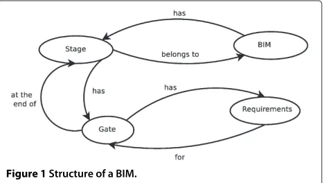
the RIBA plan of work [8], but many others exist. For this reason any model defined must be flexible enough to model all of these processes. Our approach to model this is illustrated in Figure 1.
In our approach we consider BIM to consist of a series of stages, at the end of which there is agate, identifying a set of either mandatory or optional requirements such as the presence of data within the BIM, the accuracy of data, etc. For instance, in early stages of a building lifecycle, energy efficiency figures may be rough estimates which need to be refined in later stages (for instance, when results of detailed simulations become available). This division into stages allows the tracking of the BIM model through-out the project process. In essence each stage within the model can be viewed, once it has completed, as a snap-shot of the BIM as it was at that time. This functionality will enable the use of the governance model as support for project managers, enabling the creation of reports that can be used to facilitate decision making and ensur-ing BIM compliance with standards, whether imposed by legislation, the client, or internally.
Multi user collaboration
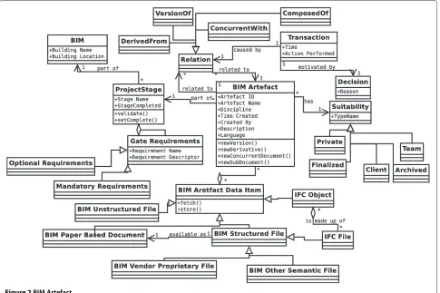
Figure 2 describes the various components that make up a BIM artefact. This diagram shows that each BIM Artefact, which itself may be made up of one or more structured or unstructured data files or IFC objects, has a set of metadata attached to it allowing it to be properly managed.
Based on British Standard 1192:2007 [13], each artefact is given a suitability that allows the modelling of its life-cycle, illustrating the different ways in which an artefact can be used. Currently we define five artefact suitabili-ties (based on who can access them): (i) Private: document only for use of owner; (ii) Team: document only for use at a team level; (iii) Finalised: document is for use by other teams; (iv) Client - document is ready for release to client; or (v) Archived - document has reached end of its lifecycle and no further alterations will be made.
Figure 2BIM Artefact.
Another important concept shown in Figure 2 is a BIM Artefact’s relationships to other BIM Artefacts. Each Arte-fact is part of a specific stage of the project - but they can also be related to other individual BIM Artefacts using the relationships previously described. An important concept that is added to this is that of a transaction. A transac-tion occurs whenever a relatransac-tionship between artefacts is created by a user [14]. The transaction entity is generated automatically, whereas the decision entity enables the user to make explicit the reasons for creating the relationship.
Figure 2 also shows all the metadata that is stored, using as a base-line, the Dublin Core metadata standard. This ensures that all elements defined in this standard are either provided explicitly within the Document object, or implicitly by its relation to data stored in other related objects within the data model.
Access rights, users, disciplines and roles
In order to enforce a fine grained access control over arte-facts, we use the concepts ofusers, disciplines, rightsand roleswithin the governance model – as shown in Figure 3:
• Users - A user is a single actor within the system. • Disciplines - An industry recognised specialisation
working on a specific aspect of a project.
• Rights - The conceptualisation of a permission to perform an operation on an artefact.
• Roles - A grouping of rights that can be applied to users or entire disciplines.
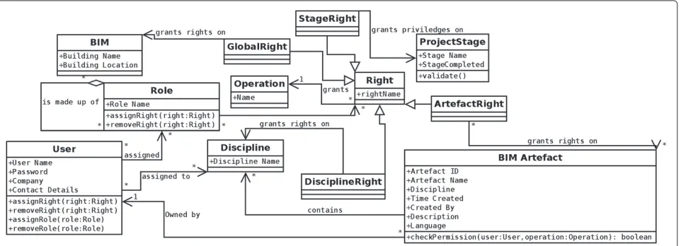
A detailed diagram of how these access rights will be implemented is shown in Figure 4. This figure illustrates the key concepts of Users, Disciplines, Roles and Rights and how they are connected. In this Figure, a right is made up of three components - i) the user/role being granted the right, ii) the operation that the right permits and iii) what artefacts the operation can be performed on.
For maximum flexibility we allow rights to be applied to an individual BIM Artefact, but also to all artefacts in the BIM, all artefacts within a stage of the project and all artefacts that belong to a particular discipline. Addition-ally, the functionality to allow role aggregation is present, allowing roles to be combined.
Figure 3Users, Disciplines and Roles.
of CometCloud [15]. This section will firstly describe CometCloud, its features and why it was selected for use in this project. We will then outline the architecture of our Cloud Computing prototype named “CloudBIM”.
CometCloud
The CometCloud system was utilised for this project due to its successful deployment in other data sharing scenarios within the computational finance area [15]. CometCloud uses a Linda-like tuple space referred to as “CometSpace" – which is implemented using a Peer-2-Peer overlay network. In this way, a virtual shared space for storing data can be implemented by aggregating the capability of a number of distributed storage and com-pute resources. CometCloud therefore provides a scalable backend deployment platform that can combine resources across a number of different providers dynamically – a key requirement for a project in the AEC sector.
The overarching goal of CometCloud is to realize a virtual computational cloud with resizable computing
capability, which integrates local computational environ-ments and public cloud services on-demand, and pro-vides abstractions and mechanisms to support a range of programming paradigms and application requirements. Specifically, CometCloud enables policy-based autonomic cloudbridgingandcloudbursting. Autonomic cloudbridg-ing enables on-the-fly integration of local computa-tional environments (datacenters, Grids) and public cloud services (such as Amazon EC2 and Eucalyptus), and autonomic cloudbursting enables dynamic application scale-out to address dynamic workloads and spikes in demand. Cloudbridging is useful when specialist capa-bility available in-house needs to be integrated with high throughput computation that can be outsourced to an external cloud provider such as Amazon. Cloud-bursting, on the other hand, enables scale-out of in-house computation and may not necessarily involve a change in capability between in-house and outsourced providers.
CometCloud is based on a decentralized coordina-tion substrate, and supports highly heterogeneous and
dynamic cloud/Grid infrastructures, integration of pub-lic/private clouds and cloudbursts. The coordination sub-strate (based on a distributed Linda-based model) is also used to support a decentralized and scalable task space that coordinates the scheduling of tasks, submitted by a dynamic set of users, onto sets of dynamically provisioned workers on available private and/or public cloud resources based on their Quality of Service (QoS) constraints such as cost or performance. These QoS constraints along with policies, performance history and the state of resources are used to determine the appropriate size and mix of the public and private clouds that should be allocated to a specific application request. Additional details about CometCloud can be found at [3].
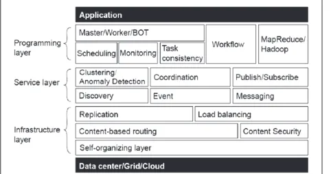
In this way, CometCloud differs from other Cloud computing environments currently available – as the focus in this system is specifically on bridging dif-ferent distributed environment through the distributed tuple space implementation. Figure 5 illustrates the architecture of the CometCloud system – which con-sists of an: (i) infrastructure layer – enabling various data access and management capability to be supported (such as replication, routing, etc); (ii) a service layer – to enable a number of common services to be supported on the infrastructure, such as pub/sub, content/resource discovery, etc; and (iii) a programming layer – which enables the other two layers to be accessed in a num-ber of ways using various programming models (such as map/reduce, master/worker, bag-of-tasks, etc). In prac-tice, an application may not use all of these capabilities, as in our scenario which makes use of the master/worker paradigm. More details about the architecture, it use and source code downloads can be found in [3,16]. Various cloud bridging solutions are now available, such as IBM’s Cast Iron Cloud Integration [17], part of the Web Sphere suite of tools for developing and deploying applications across different environments. Cast Iron enables integra-tion, through plug-ins, with a number of IBM products (such as DB2) and systems from other vendors, such as SAP and Salesforces CRM – thereby enabling integration
Figure 5Architecture of the CometCloud system.
between in-house systems and public & private Cloud environments. Many such systems remain proprietary to particular vendors however and are hard to customise to particular use scenarios.
As illustrated in Figure 5, at a lower level the Comet-Cloud system is made up of a set of computational resources each running the CometCloud overlay. When the CloudBIM system is initialised a set number of workers are initially launched on these resources, but additional workers can be started as required. The com-munication between these nodes is all done via the CometCloud communication space represented as a set of Linda-like tuples [15] which are placed into CometSpace using one of three concepts:
1. Adding a tuple - OUT; 2. Removing a tuple - IN;
3. Reading a tuple but not removing it - RD.
These nodes and their communication can be struc-tured by CometCloud to enable support for multiple development models including: Map/Reduce, Master/ Worker and the implementation of workflows (as described above).
The CloudBIM prototype
The CloudBIM prototype was constructed using Comet-Cloud’s Master/Worker programming model and consists of three main components: A client and a set masters and workers. The architecture of the CloudBIM prototype is shown in Figure 6.
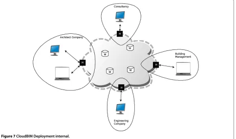
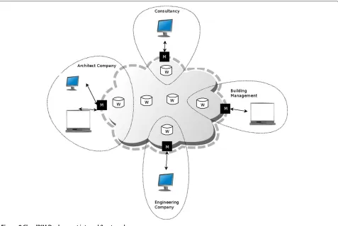
The flexibility of utilising CometCloud allows these components to be deployed in multiple configurations
such as those shown in Figures 7 and 8. Figure 7 shows a configuration where a master node is deployed within each organisation working on the project but workers nodes are deployed externally - on a third party cloud services provider such as Amazon or Azure. An alterna-tive configuration is shown in Figure 8 where masters and workers are deployed within organisations in addition to some worker nodes deployed externally.
The following sections will describe the implementa-tion of the three main components, Masters, Workers and the two clients that have been developed; a web based interface, and plug-in for Google Sketchup.
Implementation of master and worker nodes
Masters
The CloudBIM master nodes do not store any data (other than temporarily caching for performance). These master nodes act only as gateways to the CloudBIM system. They are responsible to generating XML tasks that are inserted into the CometCloud coordination space. These XML tasks essentially wrap the queries that have been provided by the user (via the client) along with data needed inter-nally by the cloud system. The format of these tasks is shown below:
<CloudBIMTask>
<TaskId> Unique ID of Query</TaskId> <AuthToken> Authorisation
Token</AuthToken>
<MasterName> Name of Master that is Origin of Query</MasterName>
<DuplicationCount> Number of data is to be duplicated</DuplicationCount> <InternalFlag> Flags whether this is
an Internal Task to be ignored by all master nodes</InternalFlag>
<Query>User Query</Query> </CloudBIMTask>
Workers
Each of the workers within the CloudBIM system hold a portion of the governance model and a subset of all the actual artefact data within the BIM. This ensures that all data is replicated allowing resilience if individual workers go off-line. The workers, in addition to storing the data, are also responsible for validating each query they receive against the governance model to determine if they should execute the query, i.e. ensure that user A has authority to update artefact B before doing so.
The interaction between masters and workers is the key to how the CloudBIM system functions. This communica-tion is done using CometCloud’s distributed coordinacommunica-tion space. Masters place XML tasks into this space and these are then read by the workers. Use of this distributed com-munication space allows for a variety of comcom-munication
Figure 8CloudBIM Deployment internal & external.
patterns to be utilised depending on the type of task being executed. These tasks can be broken down into one of four types: (i) tasks that read data; (ii) tasks that add data and (iii) tasks that remove data.
Figure 9 describes how data is retrieved from the system. Firstly a task containing an appropriate query is placed into the communication space by the master node. Each worker will read this task (using the non destructive RD function) and will determine if they have the capability to fulfil the query. If they have this ability - and the per-missions of the user identified by the token contained within the query matches those enforced by the gover-nance model, then the data will be returned to the master node. While this process is undertaken, the master node will monitor the data that is returned to it and, once it has recieved all the replies (or a timeout is exceeded) it will remove the query tasks from the communication space.
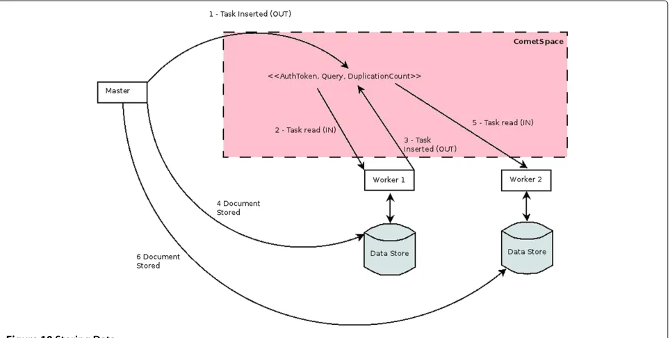
Figure 10 shows the similar process undertaken for adding new data for the system. When this type of query is executed the system must ensure that the data is duplicated across the cloud. So, when the Master receives the data from the user it will cache the data, so no delays occur for the user while duplication takes place. The query
is now inserted into the communication space. The first available worker will then remove the task, decrement the duplication count and then, as long as the dupli-cation count is above zero, re-insert the task. On task re-insertion, the worker will then request the data from the Master. This process will then repeat until the dupli-cation count reaches zero. As in the previous example, the authorization token is used to determine who can add data to the system.
The final scenario is where data is removed from the sys-tem. This process is similar to that outlined in Figure 9 - in this case a task is inserted into the communication space by the master and all worker nodes that are able to will remove the specified data (assuming the user requesting the deletion meets the requirements of the governance model). Each worker node will then send a confirmation to the master node which, once it has received all the acknowledgements (or a time-out has been exceed) will remove the task from the communication space.
Fault tolerance
Figure 9Reading Data.
availability of BIM data. As mentioned previously, the underlying CometCloud architecture consists of a pool of resources/machines running the CometCloud overlay. When the CloudBIM system is launched a set of workers, defined by IP addresses in a configuration file, are ini-tialised using nodes from this pool. If a worker fails, the procedure outlined in Figure 11 is followed. When a query
is issued, the Master node will count the number of work-ers that process the query and if a single worker repeatedly fails to respond within a certain time frame (the number of failures and the time-out value are configurable), then the worker is considered to have failed. While this is taking place user requests are still being processed because the BIM data will still be available from other workers in the
Figure 11Fault Tolerance in CloudBIM.
system (due to data duplication). Only in the case of multi-ple simultaneous failures would users be unable to retrieve data. In cases where a worker (or set of workers) loses con-nection for a long period of time (a timeout value set by an administrator) the worker will be removed from the system.
Once a worker has permanently failed, it is removed from the current list of workers and a new worker is added
from a pool of nodes that can be added to the cloud. This is done by communicating with the CometCloud overlay that will be running on the waiting node and instructing it to initialise itself as a CloudBIM worker. Once this is done, the CometCloud overlay must then be restarted to enable correct routing of messages to the new worker.
Finally, once the new worker has joined the communica-tion space, synchronisacommunica-tion may be needed to ensure that
there is sufficient duplication of BIM data. This entire pro-cess takes place transparently to the user and is done as follows:
• Each worker will send the new worker the IDs of the BIM artefacts that it holds (by placing an internal task into the communication space).
• The new worker will calculate which artefact Ids need additional duplication based on this data. • The new worker will request the artefacts needed
directly from the worker that holds them.
The same process is followed when a new worker needs to be added to the system from the pool to improve system throughput. This process is also followed when a worker that has been offline re-joins the system, this means that it can retrieve a new set of data from other workers in the CloudBIM system, removing the risk of any invalid (outdated or deleted) data from becoming available to users.
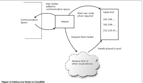
The key aspect of this fault tolerance process is that there are “spare” workers available for use in the pool.
This can be ensured in one of several ways as shown in Figure 12:
• By supplying the system with a list of IP addresses of nodes that have CometCloud installed and can be utilised.
• Utilising third party cloud providers to spawn additional virtual machines based on a defined policy. Currently this has been implemented by Rutgers using Amazon EC2 [3].
Integrating cloud computing and google sketchup
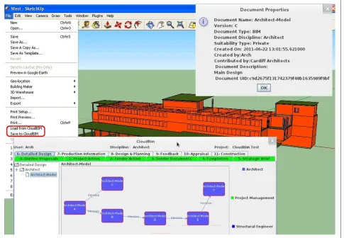
Within the CloudBIM system the client is responsible for providing the interface between users and the local mas-ter node. This is done by providing a user inmas-terface, which converts users’ actions into a query which is then com-municated to the master node in the form of a query language. We implemented two clients, a web based inter-face and a plug-in for Google Sketchup (A commonly used tool in the AEC industry). The Google Sketchup plugin is shown in Figure 13.
Figure 14CloudBIM for data processing.
The decision to utilise a query language was to enable two possible usages of the system:
1. As a capability that could be integrated into a custom user interface implemented for a specific project. 2. As a capability integrated within existing software as
a plug-in (such as existing CAD systems like Autodesk Revit [18] or Google sketchup [19]).
This allows third parties to leverage on the functional-ity provided by the CloudBIM system. An example of this would be a company that utilises their own proprietary software tools, this company could, using the CloudBIM query language, integrate their existing software tools with the CloudBIM system, possibly including develop-ment of a plug-in for their CAD software or integrating
CloudBIM into an existing project management intranet system.
The prototype CloudBIM query language is specified below in EBNF (Extended Bachus Naur Form) notation.
CLOUDBIMQUERY=DOCUMENTUPPLOAD | DOCUMENTDOWNLOAD |GOVERNANCEQUERY
GOVERNANCEQUERY = UPDATEQUERY | OTHER QUERY UPDATEQUERY = ’update’,’ ’,OBJECT,’
’,FIELDLIST,’ ’,’set’,’ ’,FIELDLIST OTHERQUERY = (’get | ’add’ | ’delete’),’
’,OBJECT,’ ’,FIELDLIST DOCUMENTDOWNLOAD=’fetchdoc’,’
’,FIELDLIST,[’ ’,’all’]
DOCUMENTUPLOAD = ’adddoc’,’ ’,FIELDLIST, [’ ’,’(’,RELATION,’,’,RELATION,’)’]
OBJECT=’ProjectStage’|’GateRequirement’ |’DocumentSuitability’|’Discipline’ |’Operation’|’Role’|’Right’|’User’ |’Notification’|’Flag’|’NotificationType’ RELATION=RELTYPE,’ ’,<ID> RELTYPE=’ver’|’der’|’comp’|’conc’ FIELDLIST=FIELD,’,’,FIELD FIELD=OBJECT,’=’,FIELDVALUE FIELDVALUE=VALUE|(’(’,VALUE,’,’,VALUE,’)’)
For the sake of brevity the terms ID (a unique ID) and VALUE (a string) are not defined, also omitted are commands used to authenticate a user. The Cloud-BIM query language defines six key commands:get, add, delete, update, adddoc and fetchdoc. These commands allow the manipulation of objects within the governance model, however it should be noted that not all objects are able to be directly manipulated by users, some are created/updated as a side effect of other queries i.e. spec-ifying the relationship of a new document will lead to the automatic creation of Relationship and Transaction objects as necessary by using data supplied in theadddoc command. Theadddocandfetchdoccommands separate the uploading and downloading of documents from the CloudBIM system from the manipulation of the objects within the governance model. Additionally, it is worth not-ing that the fetchdoc command can be used to return either all matching documents (not always desirable) or just the first match.
CloudBIM for data processing
Workers within the CloudBIM system may also be used to launch external simulations (in batch mode), the results of which are also stored as artefacts. Access to these arte-facts is then based on our governance model. This process enables the integration of third-party executable software, in addition to static artefacts that have been pre-generated and stored. The use of workers for processing operates in a similar way to that outlined previously, firstly a task is placed into the communication space that describes: (i) the program to be executed; or (ii) the artefacts that are needed as input to the program. These tasks will then only be read by workers that possess the applica-tion that the task is requesting. Once a worker has read the task it will place new internal tasks into the com-munication space to request any data it does not hold. Once the data has been received, the task will execute and a reply will be sent giving the artefact ID of the output data.
When utilising workers for data processing there are two different modes of operation that are supported:
• Utilising the processing of the existing workers that are used for data storage.
• Utilising CometCloud’s CloudBursting capability to spawn workers solely for data processing.
The second type of execution we envisage as the most common mode of operation, especially in cases where the tasks being executed require either specialised software to be installed, or have large resource requirements. In these cases additional workers are spawned on a cloud service such as Amazon EC2, but, because they are temporary workers, are only permitted to access the communication space via a RequestHandler, this is shown in Figure 14. This restriction is imposed because we do not want exter-nal workers to process any data storage tasks as they are temporary workers with a lifespan of the length of a single computation task.
This ability to spawn extra “external” workers is highly useful and has the ability to be expanded to include a large number of common industry tasks:
• Energy Simulations
• Rendering of building models. • Automatic Clash Detection.
Conclusion
The CloudBIM project was a feasibility study that aimed to explore the feasibility and potential for utilizing Cloud capability to address data storage and processing needs of stakeholders in the AEC sector. In the course of this project we have explored some of the technical and non-technical issues related to the outsourcing of BIM data into a Cloud Computing environment. Various other approaches currently exist to support collaborative work-ing in the construction sector – most of these, however, are focused on the use of a centralised server that enable upload/download of BIM data – such as BIM server [20] and ProjectWise [21] from Bentley Systems. We believe such an approach limits the kinds of interactions that can be supported within the AEC sector and more effective approach would involve integration of data storage and processing capability across different industry partners involved a particular project.
We have found through a process of consultation that, unsurprising, the majority of the barriers to the adoption of Cloud-based BIM have been related to ensuring that the
Table 1 Performance of failure tolerance and addition of new workers
Activity Time/s
Single Worker Failure 3.22
Adding 1 New Worker 3.59
Adding 2 New Workers 3.49
Table 2 Performance overhead measurements
File size/mb Download overhead/s Download speed MByte/s Upload overhead/s Upload speed MByte/s
100 0.58 10.75 1.48 8.70
200 0.67 10.97 1.45 7.92
500 0.69 10.06 1.16 8.09
1000 0.84 9.94 1.53 5.80
design of a system is in compliance with complex industry requirements.
To this end a governance model and a prototype have been constructed and we have evaluated these in three ways. Firstly, the governance model has been validated using further industry review. Secondly, the governance model and the technical implementation has been eval-uated by the utilising a number of use cases supplied by our construction project management industry partner. Finally, a technical performance analysis has been carried out of using the operations in our query language and CloudBIM’s fault tolerance capability.
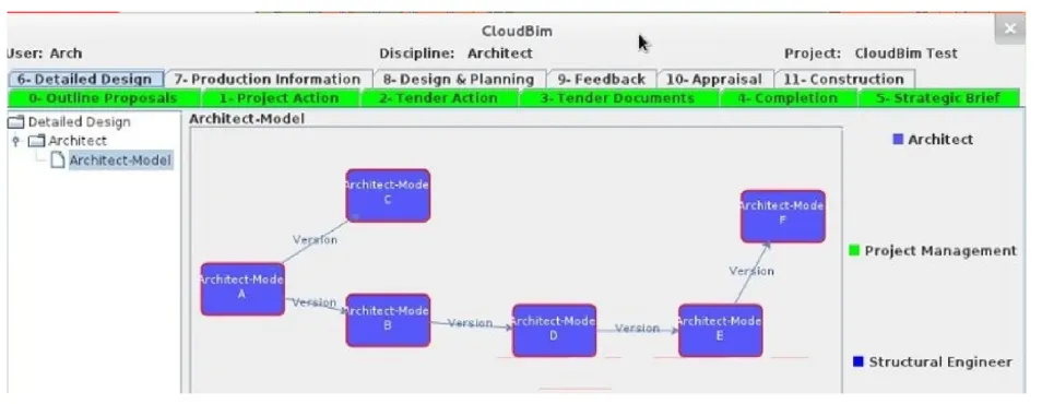
The results that we have so far are promising: The indus-try has reacted positively to the idea of the governance model and the functionality that it provides. The trials from the case study have shown the governance model is able to correctly model the scenarios presented to it. Figure 15 shows one example of this, where the CloudBIM system was able to successfully track a complex structure of versioning of the architects model.
The results of the performance analysis are also promis-ing. In conducting this experiment we firstly timed several key operations - the dynamic addition of new workers to the system and the time to recover from worker failure. The results of this experiment is shown in Table 1. Sec-ondly, we also measured the governance overhead - that is the extra time taken for upload/download of files to the CloudBIM system compared to standard file uploads to the same machine and the upload/download speeds when transferring BIM data to the CloudBIM system. These results are shown in Table 2.
In summary, both sets of results are promising and show that the CloudBIM System is able to:
• Recover from single worker failure.
• It is able to add multiple new workers in under 4 seconds.
• When transferring BIM data it can achieve an download speed of approximately 10MByte/s and an upload speed of 7.5MByte/s.
• The overhead of using the governance model to manage access to the BIM data is less than two seconds per query.
One of the interesting lessons learnt in this project, has been examining a number of other disciplines that are
attempting to solve the problem of out-sourcing their data storage. It was interesting to find that many of these dis-ciplines are facing different, but related problems and it is surprising that in many cases there were experiences from one discipline that can be carried over into another.
However, it has also become apparent that because the majority of buildings are unique, meaning each must be treated as a prototype, and that the lifetime of BIM data is far longer than the lifetime of many data-sets (the lifetime of the building), the problems faced in this industry are unique and challenging. Our future objective is to make CloudBIM more scalable and use it in a realistic end user system. This will involve integration of various backend systems that host BIM data using the Worker model used in CometCloud. These systems can range in complexity from a structured data base to a file system. Our current work is focused on developing suitable plugins to enable such integration to be supported.
Competing interests
The authors declare that they have no competing interests.
Authors’ contributions
THB from Cardiff University School of Engineering developed the BIM Governance model and the CloudBIM prototype. OFR from the Cardiff University School of Computer Science and Informatics provided Cloud Computing expertise and supervised the development and testing of the prototype. YYR from Cardiff University School of Engineering conducted the industry consultation and provided domain specific expertise in the development of the BIM Governance Model. MP from RDI2/CAC at Rutgers University provided description of CometCloud and associated use of CometCloud in other scenarios. All authors read and approved the final manuscript.
Acknowledgements
The research was funded by the EPSRC under contract EP/I034270/1.
Author details
1School of Engineering, Cardiff University, 5 The Parade, Roath, Cardiff, UK. 2School of Computer Science & Informatics, Cardiff University, 5 The Parade,
Roath, Cardiff, UK.3RDI2/CAC/Dept. of Electrical & Computer Engineering,
Rutgers University, Piscataway, NJ 08854-8058, USA.
Received: 19 October 2012 Accepted: 24 January 2013 Published: 4 April 2013
References
1. UK Cabinet Office, Government Construction Strategy (2011) https:// www.gov.uk/government/uploads/system/uploads/attachment_data/ file/61152/Government-Construction-Strategy_0.pdf Accessed November 2012
3. Kim H, Parashar M (2011) CometCloud: An autonomic cloud engine, cloud computing: principles and paradigms. chap. 10. John Wiley & Sons, Inc., pp 275–297. http://onlinelibrary.wiley.com/doi/10.1002/
9780470940105.ch10/summary
4. Grilo A, Jardim-Goncalves R (2011) Challenging electronic procurement in the AEC sector: A BIM-based integrated perspective. Automation in Construction 20: 107–114
5. Vorakulpipat C, Rezgui Y, Hopfe CJ (2010) Value creating construction virtual teams: A case study in the construction sector. Automation in Construction 19: 142–147
6. International Standard (ISO) 16739:2005 - Industry Foundation Classes 7. Succar B (2009) Automation in Construction 18: 357–375
8. Royal Institute of British Architects (RIBA) Plan of Work. Available at: http://www.ribaplanofwork.com/. [Last accessed: Jan 17, 2012] 9. Serror M (2007) Shared computer-aided structural design model for
construction industry (infrastructure). Comput Aided Des 40: 778–788 10. Singh V (2010) A theoretical framework of a BIM-based multi-disciplinary
platform. Automation in Construction 20: 131–144
11. Rezgui Y, Cooper G, Brandon P (1998) Information management in a collaborative multiactor environment: the COMMIT aApproach. J Comput Civil Eng 12: 136–145
12. Rezgui Y, Hopfe C, Vorakulpipat C (2010) Generations of knowledge management in the architecture, engineering and construction industry: an evolutionary perspective. Adv Eng Inform 24: 219–228
13. British Standards Institute (BSI): British Standard 1192:2007 – Collaborative production of architectural, engineering and construction information, Code of practice
14. Cooper G, Cerulli C, Lawson BR, Peng C, Rezgui Y (2010) Tracking decision-making during architectural design. Electron J Inf Technol Construction 10: 125–139
15. Kim H, Chaudhari S, Parashar M, Martyy C (2009) Online Risk Analytics on the Cloud International Workshop on Cloud Computing In: conjunction with the 9thIEEE International Symposium on Cluster Computing and the Grid, pp pp 484–489
16. CometCloud – available at: http://nsfcac.rutgers.edu/CometCloud/. [Last accessed: Jan 10, 2013]
17. IBM WebSphere Cast Iron Cloud Integration – available at: http://www-01.ibm.com/software/integration/cast-iron-cloud-integration/. [Last accessed: Jan 10, 2013]
18. Autodesk Revit Architecture – available at: http://www.autodesk.com/ products/autodesk-revit-family/overview. [Last accessed: Jan 15, 2012] 19. 3D Modelling Software from Google (version 8) – available at: http://
www.sketchup.com/. [Last accessed: Jan. 15, 2012] 20. bimserver.org
21. http://www.bentley.com/en-US/Products/projectwise+project+team+ collaboration/
doi:10.1186/2192-113X-2-8
Cite this article as:Beachet al.:Cloud computing for the architecture, engineering & construction sector: requirements, prototype & experience.
Journal of Cloud Computing: Advances, Systems and Applications20132:8.
Submit your manuscript to a
journal and benefi t from:
7 Convenient online submission
7 Rigorous peer review
7 Immediate publication on acceptance
7 Open access: articles freely available online
7 High visibility within the fi eld
7 Retaining the copyright to your article