The Far Field Pattern Analysis of Vertical
and Horizontal Dipole Embedded in a
Dielectric Slab
G.Anjaneyulu1 1
Associate Professor, Department of ECE, MVGR College of Engineering, Vizianagaram
Email: [email protected]
Dr.G.S.N.Raju2 2
Professor in Department of ECE, Andhra University, Visakhapatnam
Email: [email protected]
Abstract:
The radiation characteristics of dipole antenna embedded in a dielectric slab depend on dielectric material properties. In this paper, the far field radiation characteristics of vertical and horizontal dipole antennas embedded in a dielectric slab of different thickness with a ground plane is considered and patterns are derived applying reciprocity theorem. Numerical results are presented in a graphical form to show the effects of the dielectric material on antenna pattern
Key words: Horizontal Dipole, Vertical Dipole, Reciprocity Theorem 1. Introduction:
An antenna is an essential part of any electronic system which transmits or receives electromagnetic energy in a wireless fashion. Without an antenna, electromagnetic energy will be localized, and interaction at a distance between unconnected points in space does not occur. It must be an efficient radiator or collector of electromagnetic energy, and it should direct the energy to certain desired directions and suppress it in other specified directions. Thus one must be concerned not only with conversion efficiency of an antenna, but also with its radiation pattern [1],[5]. The behavior of electromagnetic waves between a transmitter and a receiver is important as the received power depends on the propagation characteristics as well as the location of transmitting and receiving antenna.
John. R. Carson [3] has presented the generalized Rayleigh theorem and the Sommerfeld-Pfrang theorem. These theorems comes under Reciprocal theorems plays a great theoretical importance in radio communications R.F. HarringTon [2] and J.D. Kraus [4] described a method for evaluating any network constructed of linear isotropic dielectric material which has a symmetrical impedance matrix. This network consists of two antennas. The idealized far field radiation pattern of an infinitesimal Hertzian dipole in and over a perfect dielectric coated conductor is derived by D.B.Brick et al. [6].
The phenomena associated with the interaction of electromagnetic fields and dielectric slabs have attracted considerable attention. The G.N.Tsandoulas [10] considered the case of the structure consisting of a horizontal electric dipole above a grounded dielectric slab is examined.
E.H.Newman [11] has done good work on strip antennas in a dielectric slab by using method of moment technique.
The general problem of solving for the fields of a dipole in a dielectric slab is straightforward but lengthy with desired numerical data. However, the solution for the far field pattern can be simplified by using the reciprocity theorem and the known field distribution setup in the dielectric slab of incident plane wave. These types of embedded dipole antennas are useful in point to point communication and radars [8].
In the present paper a dipole antenna embedded in a dielectric slab is considered. The radiation characteristics of dipole antenna depend on dielectric material characteristics as well as dielectric slab thickness [11-14]. The purpose of this work is to determine far field radiation.
2. Analysis:
Many antenna properties are the same for both transmitting and receiving. The reciprocity theorem greatly simplifies antenna parameter calculations and measurements both transmitting mode and receiving mode. Reciprocity can be understood via Maxwell’s equations.
antennas generating of harmonically oscillating electromagnetic field in an identical environment with an
isotropic medium. The field generated by the two antenna systems will be labeled as
J
ˆ
a,H
ˆ
a,E
ˆ
a andb
J
ˆ
,H
ˆ
b,E
ˆ
b. These are solution of following equationsa a
j
H
E
curl
ˆ
ˆ
(1)a b
a
J
j
E
H
curl
ˆ
ˆ
ˆ
(2)b b
j
H
E
curl
ˆ
ˆ
(3)b b
b
J
j
E
H
curl
ˆ
ˆ
ˆ
(4)The wave equation for
H
ˆ
a,E
ˆ
a,H
ˆ
b,andE
ˆ
bare given bya a
a
E
j
J
E
ˆ
2ˆ
ˆ
(5)a a
a
H
J
H
ˆ
2ˆ
ˆ
(6)b b
b
E
j
J
E
ˆ
2ˆ
ˆ
(7)b b
b
H
J
H
ˆ
2ˆ
ˆ
(8)The above field characteristic are solved with the help of reciprocity theorem is given below.
s
b a
a b
v
E
aE
bE
bE
adv
n
E
E
E
E
]
ds
ˆ
ˆ
ˆ
ˆ
[
ˆ
ˆ
ˆ
ˆ
ˆ
(9)Where
n
ˆ
denotes the outward unit vector vertical to the surface S enclosing the volume.With the help of equations 1,2,5 & 6 equation 9 becomes
s
b a a b
v
J
bE
aJ
aE
bdv
n
E
H
E
H
]
ds
ˆ
ˆ
ˆ
ˆ
[
ˆ
ˆ
ˆ
ˆ
ˆ
(10)In the case of an electrically perfect conducting body inside the volume V in an otherwise infinite domain then the surface S consists of two parts, one at infinity and other corresponding to the scattering body denoted by Sd. At infinity fields satisfy the radiation condition and on Sd,
n
ˆ
E
ˆ
a
0
andn
ˆ
E
ˆ
b
0
then equation (10)reduces to
J
E
dv
J
E
dv
ba v
a b v a b
ˆ
ˆ
ˆ
ˆ
(11)Fig.1- Coordinates of dipole a and b.
The Carson’s reciprocity theorem is applied to line sources like infinitesimal electrical dipoles as a result the volume integrals in equation (11) is reduces to line integrals. These line integrals give the following results.
l
aI
al
ˆ
a.
E
ˆ
ab
l
bI
bl
ˆ
b.
E
ˆ
ba (12)Where
E
abis the electric field of dipole ‘b’ evaluated at dipole ‘a’; andE
bais the electric field intensity ofdipole ‘a’ evaluated at dipole ‘b’,
l
ˆ
aandl
ˆ
b are unit vectors in the direction of dipole ‘a’ and dipole ‘b’,respectively ;
l
aandl
b are the effective lengths of two dipoles ;I
aand
I
b are their terminal currents whentransmitting.
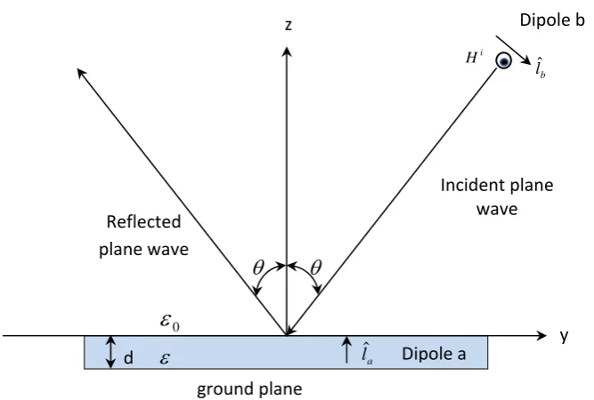
The reciprocity theorem in equation (11) is applicable to dipoles with a slab of large but finite width. Consider the problem of a short electric dipole designated as dipole ‘a’ embedded in a dielectric slab as shown in fig. 1.
Dipole ‘b’ has been chosen as the second source the r, θ and
components of the electric field of dipole ‘a’ can be found first by orienting ‘ b’ in the r, θ and
directions respectively and then applying (12) in each case. It is found thatr b a b b
a a
ra
l
E
I
l
I
l
E
ˆ
.
(13)
a b
b b
a a
a
l
E
I
l
I
l
E
ˆ
.
(14)
a b
b b
a a
a
l
E
I
l
I
l
E
ˆ
.
(15)Where
E
br,E
bandE
bare the electric field vectors of r, θ and
oriented dipole ‘b’ evaluated at dipole ‘a’(
x
,
y
,
z
)
.a a ra
E
E
E
,
,
Is the r, θ and
components respectively of Ea , the electric field of dipole ‘a’(
x
,
y
,
z
)
evaluated at dipole ‘b’ (r,θ,
).Equations (13 -15) are a general expression for the electric field Ea radiated by dipole ‘a’ as function of position (r,θ,
) where dipole ‘b’ is located. According geometry show in the figure 1, the far field ofE
a are only θand
component. Therefore the incident field generated by dipole ‘b’ can be approximated as a plane wave near
i
H
Dipole‘b’
ZY Dipole
‘a’
d r
ground plane 0
x
the origin when
oriented corresponds to a plane wave with perpendicular polarization, and that generated by dipole ‘b’ when θ oriented to a plane wave with horizontal polarization.3. Formulation:
3.1 The radiation pattern of vertical dipole embedded in a dielectric slab with a ground plane.
As shown in fig 2 θ oriented dipole ‘b’ is generated uniform plane wave at a distance ‘r’ from the origin incident on a plane dielectric slab in the YZ plane. Since the plane wave is with horizontal polarization the field in the slab is given by
z bz y by x bx
b
E
a
E
a
E
a
E
ˆ
ˆ
ˆ
(16)Fig. 2-Uniform plane wave incident on a plane dielectric slab with vertical polarization.
When a perfect conducting ground plane is presented at z= - d, the field in the slab is given by
0
bx
E
(17)
0 j Nz j Nz j ysini
by
Ae
Be
e
NH
E
(18)
sin
0 j Nz j Nz j ysini
bz
Ae
Be
e
H
E
(19)Where
H
0i is the magnetic field intensity of dipole b (r, θ,
) evaluated at the origin.r
e
i
l
j
H
r j
b b i
4
0
(20)Nd j p
p
e
A
2
1
1
(21)Nd j p
Nd j p
e
e
B
2 2
1
)
1
(
(22)p
= boundary reflection coefficient with horizontal polarization
b
lˆ
i
H
Dipole b
Incident plane
wave
Reflected
plane wave
a
lˆ Dipole a d
0
ground plane
z
N
N
r r
cos
cos
(23)
2sin
rN
(24)From above analysis the radiation pattern of a vertical dipole in a dielectric slab is given by
0
a
E
(25)
sin2
4
sin
j Nz j Nz j yr r j a a
a
Ae
Be
e
e
i
l
j
E
(26)3.2 The radiation pattern of a horizontal dipole embedded in a dielectric Slab with a ground plane
When a ground plane is present at z=-d, the field in the dielectric slab on which a plane wave with perpendicular polarization is incident at
/
2
is given by
sin
0
y j Nz j Nz
j i
bx
E
Ce
De
e
E
(27)0
by
E
(28)0
bz
E
(29)Where
E
0i= the electric field intensity of dipole ‘b’ evaluated at the origin.r
e
i
l
j
E
r j
b b i
4
0 0
(30)Nd j
e
C
2
1
1
(31)Nd j
Nd j
e
e
D
2 2
1
)
1
(
(32)
= boundary reflection coefficient with perpendicular polarization.N
N
cos
cos
Fig.3-Uniform plane wave incident on a plan dielectric slab with horizontal polarization.
For a horizontal dipole with
l
ˆ
a
cos
0a
ˆ
x
sin
0a
ˆ
y in a dielectric slab with ground plane, the radiation pattern is found to be
0 0 sin4
cos
j Nz j Nz j y rj a
a
a
Ce
De
e
r
e
i
l
j
E
(34)
0 sin2
4
sin
j Nz j Nz j y rj a
a
a
Ae
Be
e
r
e
i
Nl
j
E
(35)The general solution for a dipole at (x, y, z) and the field point at (r, θ,
) can be obtained merely by transformation of coordinates due to rotation of x-y plane around the z- axis. This is done simply by replacing
0
/
2
by
0
, or
0 by
0
/
2
and y by
x
cos
y
sin
. Again by equations (13), (14) and (15) the radiation patterns of perpendicular and horizontal dipoles are readily found.Vertical dipole in a dielectric slab with ground plane.
E
a
0
(36)
( sin cos sin sin )2
.
4
sin
j Nz j Nz j x yr j a a
a
Ae
Be
e
r
e
i
l
j
E
(37)Horizontal dipole with
l
ˆ
a
cos
0a
ˆ
x
sin
0a
ˆ
yin a dielectric slab with ground plane.
( sin cos sin sin )0
0
.
4
)
sin(
j Nz j Nz j x yr j a a
a
Ce
De
e
r
e
i
l
j
E
(38)
( sin cos sin sin )2
0
.
4
)
cos(
j Nz j Nz j x yr j a a
a
Ae
Be
e
r
e
i
Nl
j
E
(39)4. Results
By taking the magnitudes of equations (37) and (38) the simpler expressions are obtained for the computation of far field pattern and they are listed below for a dipole in a dielectric slab. In these expressions subscript ‘a’ is suppressed since there is one dipole at –d < z < 0 radiates.
θ θ
b
lˆ
i
E
Dipole b
Incident plane
wave
Reflected
plane wave
z
y
a
lˆ Dipole a d
ε0
ε
ground plane
x
4.1 Dielectric slab with a ground plane
Vertical dipole
(
E
0
)
2 2 2 2
1/2sin
)
1
(
cos
)
1
(
)
(
cos
sin
)
1
(
)
(
Nd
Nd
d
z
N
K
E
p p r p
(40)Horizontal dipole
2 2 2 2
1/20
sin
)
1
(
cos
)
1
(
)
cos(
)
(
sin
)
1
(
)
,
(
Nd
Nd
d
z
N
N
K
E
p p r p
(41)
2 2 2 2
1/20
sin
)
1
(
cos
)
1
(
)
sin(
)
(
sin
)
1
(
)
,
(
Nd
Nd
d
z
N
N
K
E
r
(42)Where
r
i
l
K
a a
2
2
0
.Based on above formulae the far field patterns of dipole in a dielectric slab for different dielectric slab thickness is considered and graphs are plotted.
0 10 20 30 40 50 60 70 80 90
0 0.1 0.2 0.3 0.4 0.5 0.6 0.7 0.8 0.9 1 |E |/ K lamda/10 lamda/4 lamda/2
0 10 20 30 40 50 60 70 80 90 0
0.1 0.2 0.3 0.4 0.5 0.6 0.7 0.8 0.9 1
|E
|/
K
lamda/10 lamda/4 lamda/2
Fig: 2Vertical dipole far field patterns of dielectric slab thickness d=/10, /4, /2 r=1
0 10 20 30 40 50 60 70 80 90
0 0.05 0.1 0.15 0.2 0.25 0.3 0.35 0.4 0.45
|E
|/
K
lamda/10 lamda/4 lamda/2
Fig: 4 Horizontal dipole far field patterns of dielectric slab thickness d=/10, /4, /2 r=1 Conclusion
It is evident from the results that horizontal dipole in a dielectric slab is more advantageous than that of vertical dipole in certain respects. The far field of a vertical dipole in a dielectric slab has only a component, hence it is linearly polarized, that of horizontal dipole having and components. The phases of and are generally not equal. As a result horizontal dipole in a dielectric slab is elliptically polarized. Due to the discontinuity of vertical component of E across the boundary the dielectric has a stronger effect on the gain of a vertical dipole than that of horizontal dipole. For different values of dielectric constants as well as different values of slab thickness, the far field patterns of vertical and horizontal dipoles in a dielectric slab are generated and the results are shown in figs.(1 to 4).
References:
[1] G.S.N.RAJU, “Antenna and wave propagation,” Pearson Education, Singapore, 2005.
[2] R.F.Harrington, “Time Harmonic Electromagnetic Fields” McGraw-Hill Book Co., New York, N.Y., p.117; 1961.
[3] J.R.Carson, “Reciprocal theorems in radio communication,” PROC.IRE, vol. 17, p. 952-956; June, 1929.
[4] J.D.Kraus, “Antennas,” McGraw-Hill Book co., New York, N. Y., p.77; 1950.
[5] G.S.N.RAJU, et.al “Radiation Patterns of arbitrarily oriented radiating elements” proc.EMI/EMC,P.458-465.
[6] D.B.BRICK, “The radiation of a Hertzian dipole over a coated conductor,” Proc. IEE, London, vol. 102, pt. C, p. 104; 1955.
[7] G.S.N.RAJU, et.al “Generation of narrow beams from an array of short collinear dipoles using a new type of aperture distribution”
AP-S VOL.2 P. 709-712.1989.
[8] Chjin Chung, “The radiation pattern of an array of dipoles in a dielectric slab” Proc. Antennas and Propagation, IEE, vol -12, Issue-4,
July 1964.
[9] G.S.N.Raju, “Electromagnetic field theory and Transmission lines” Pearson Education Singapore, 2008 2nd Edition.
[10] G.N.Tsandoulas “Excitation of a Grounded Dielectric slab by Horizontal dipole” IEEE Transactions on Antennas and Propagation,
Vol.Ap-17, No.2 March 1969.
[11] E.H.Newman, “Strip antennas in a Dielectric slab” IEEE Transactions on Antennas and Propagation, Vol.Ap-2, No.5 Sep 1978.
[12] S.R.J.Bruek, “Radiation from a dipole Embedded in a Dielectric slab” IEEE Vol.6 No.6 Nov/Dec 2000.
[13] Matthew N.O.Sadiku, “Principles of Electromagnetics”Oxford University press 16th impression New Delhi, 2012.
[14] G.S.N.Raju “Microwave Engineering” IK International Publishers New Delhi.
0 10 20 30 40 50 60 70 80 90
0 0.1 0.2 0.3 0.4 0.5 0.6 0.7
|E
|/
K