EXPERIMENTAL INVESTIGATION &
NUMERICAL ANALYSIS OF
COMPOSITE LEAF SPRING
K. K. JADHAO
Associate Prof., Mechnical Engg. Dept.
B.N.C.O.E., Pusad – 445215 Dist. Yavatmal (M.S.) India [email protected]
DR. R.S DALU
Associate Prof., Mechnical Engg. Dept. Govt.College of Engineering Amravati (M.S.) India
Abstract :
The Automobile Industry has shown keen interest for replacement of steel leaf spring with that of glass fiber composite leaf spring, since the composite material has high strength to weight ratio, good corrosion resistance and tailor-able properties. The objective of present study was to replace material for leaf spring. In present study the material selected was glass fiber reinforced plastic (GFRP) and the polyester resin (NETPOL 1011) can be used which was more economical this will reduce total cost of composite leaf spring. A spring with constant width and thickness was fabricated by hand lay-up technique which was very simple and economical. The experiments were conducted on UTM and numerical analysis was done via (FEA) using ANSYS software. Stresses and deflection results were verified for analytical and experimental results. Result shows that, the composite spring has stresses much lower than steel leaf spring and weight of composite spring was nearly reduced up to 85%.
Keywords:Composite materials, composite leaf springs, FEA .
1. Introduction
To meet the needs of natural resource conservation and energy economy, automobile manufacturers have been attempting to reduce the weight of vehicles in recent years [1] The suspension spring is one of most important system in automobile which reduce jerk, vibration and absorb shocks during riding..
Fiber-reinforced polymers have been vigorously developed for many applications, mainly because of the potential for weight savings. Other advantages of using fiber-reinforced polymers instead of steel are: (a) the possibility of reducing noise, vibrations and ride harshness due to their high damping factors; (b) the absence of corrosion problems, which means lower maintenance costs; and (c) lower tooling costs, which has favorable impact on the manufacturing costs [2]. Springs are crucial suspension elements in cars, necessary to minimize the vertical vibrations, impacts and bumps due to road regularities[3]. The functions of the suspension springs for an automobile are to maintain a good control stability and to improve riding comfort [4,] due to composite design and manufacturing, complications arise; for example, the change from relatively isotropic-homogeneous steel alloys to anisotropic in homogeneous fiber reinforcement plastic has not yet been achieved [5].
The behavior of steel leaf spring is non linear, relatively high weight, and change in solid axle angle due to weight transfer specially during cornering of vehicle, that will lead to over steer and directional instability under such situation it is very difficult for driver to control vehicle, these are some defect of metallic leaf spring so considering automobile development and importance of relative aspect such as fuel consumption, weight, riding quality, and handling, so development of new material is necessary in the automobile industry.
Many papers were devoted to find spring geometry. The recently vehicle such as Ford, and Volvo buses are using leaf spring made up of carbon fiber as it gives good advantage but costly. So in this select glass fiber and general purpose resin for spring material on the basis of cost factor and strength.
2. Problems Identification
The objective of present work is to design, fabricate and experimental testing and analysis of composite spring made up of E-glass fiber, chopped strands mat and epoxy resin (general purpose resin) with constant width and thickness throughout its length.
3. Materials & Method
The material used as coarsely woven E-glass fiber having density 400 gsm. and Glass fiber chopped stand mat (175-450 gsm) which gives maximum tensile strength, toughness and low cost. The resin selection was main factor because it influences the economy of leaf spring for reducing prize,. The resin used as Dobeckot 520 F. The hardener 758 is used with this resin.(general purpose resin) the prepared matrix it consist of 10:1 mass ratio the mass ratio of resin to hardener to fiber were calculated for each weight percentage composite based on size of mold, desired thickness of composite and density of fiber and epoxy. Each. % wt prepared in separate jar. In order to facilitate wetting of fibers and epoxy resin with pot life of 2 h is selected.
4. Design Of Steel Leaf Spring
4.1 Design Parameter of Steel Leaf Spring
Parameters of the steel leaf spring used in this work is given below:-.
Material selected –Steel= 55SiMn90, Tensile strength=1962 N/mm2, Yield strength = 1470 N/mm2, Young’s modulus E=2.1-1.05 N/mm2, Design Stress=653N/mm2, Total length= 1010mm, The arc length between the axle seat and the front eye = 120mm, Spring rate= 31.98 N/mm, Normal static loading = 2943 N, Available space for spring width = 45mm, Spring weight = 13.6 Kg.
Let,
δmax =120 mm, σmax =2000 N/mm2, Factor of safety =2.5,Weight (W) = 2943 N, Length L=505 mm,E= 11.9 GPa 3
bt
I
12
K req. =25 N/mmLets find the safe value of b, t that would satisfy three condition as σa≥σ., δmax≥δ, K ≥ K req.
1) Let, b = 45 mm , t = 20 mm
Step-1
max a
factor of safety
a
2000 2.5
= σa =800 N/mm
2 Step-2 2 6WL bt ,
2 6 2943 50545 20
= σ = 495.405 N/mm2 σa≥σ. Thus, value for b, t satisfied 1st condition.
Step- 3. I bt3 12
3 45 20 12 WL3 3EI
3 32943 505
3 11.9 10 30000
= 353.89 mm δmax≤δ
Thus, value for b, t fails it does not satisfied 2nd condition.
Finally It was found that b = 45mm, t = 30mm and L = 505 mm, were safe value for composite leaf spring that would satisfy all three condition. So, we took these dimensions for fabricating composite leaf spring.
4.2 Composite fabrication
Preparation of mould:- Material used as Plywood. The mold was fabricated as per desired dimension. Arc length = 1160mm. length of mould= 1010mm, width= 45mm, arc height at axle=120 mm. The constant cross section design which ensures the fiber pass continuously without interruption along length direction, which is advantageous to fiber reinforced structure. The glass fiber were cut to desired length, so that they can be deposited on mold layer- by layer during fabrication of composite leaf spring. Apply the wax/gel.. Prepare the solution of resin & Place the first layer of glass fiber chopped mat on mould followed by epoxy resin solution over mat. Wait for 5-10 min. Repeat the procedure till the desired thickness was obtained. The duration of the process may take up to 25- 30 min. And finally remove the leaf spring from mould.
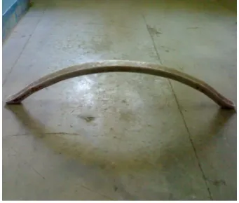
Fig. 1: Prepared specimen of composite leaf spring Fig. 2: Graph Load vs Deflection
The prepared sample was tested for their flexural strength under three point bend test in Instron testing machine with cross speed of 2 mm/min for all mechanical flexural tests the spring was loaded from zero to maximum deflection and then back to zero.
Testing of composite & steel leaf spring are takes place on UTM .Various specification of UTM are as follows:- Make:- Heico New Delhi Model No.:- HL 9C:10 Capacity:- 20 ton Least weight- 10 kg. Maximum weight- 5 ton Dial gauge least count:-0.01mm
5. Experimental Test
In the experimental analysis the comparative testing of mono composite leaf spring and the steel leaf spring are taken. The deflection or bending tests of both the spring for comparative study is taken on the universal testing machine.
5.1 Experimental Test of Steel Leaf Spring
Move the plunger up to desired height so that we can fix the fixture and leaf spring for test. Fix the position of fixture. On the fixture place the specimen. Set the universal testing machine. Apply the loads in steps of 20 kg gradually. Note down the deflection readings.
Table-1 Deflection between composite and steel leaf spring.
…
6. Analysis of Composite Material
The element SHELL 99, SOLID 46 are the best suited for modeling of composite material. SHELL 99 is an 8 – node, 3D shell element with six degree of freedom at each node. The advantage of SOLID 46 is that we can stack several elements to model more than 250 layers. Here selected element was SOLID 46.
Table 2 Stress analysis of composite and steel leaf spring
Performing a Static Analysis
The procedure for a static analysis consists of these tasks:
1. Build the Model 2. Define Parameters
The parameters for building the composite leaf spring are as follows-
Young's modulus is 11.9 GPa (EXX) value is 11900 MPa, Poison ratio is 0.217 XY(PRXY) value is 0.217 Length of cantilever beam =505mm, Width of cantilever beam.= 45mm, Height of cantilever beam. = 30mm
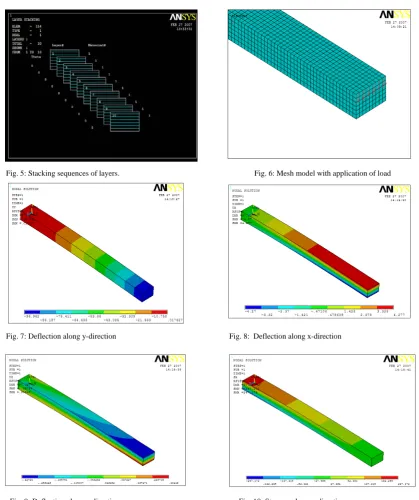
3. Stacking Sequence of Layers.
The stacking sequence of layer are shown fig having unidirectional fibre with stacking angle of zero.
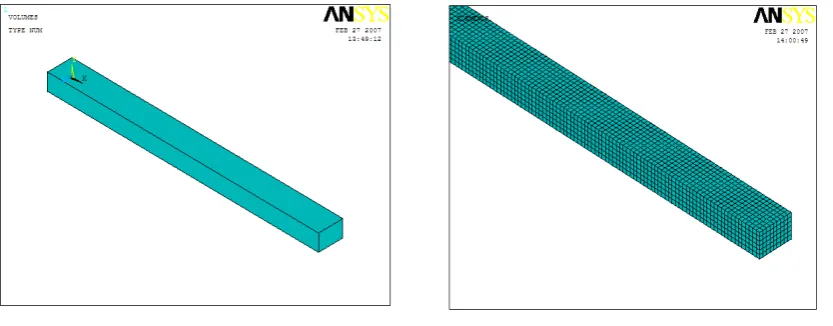
Fig. 3: Finite element model of composite leaf spring. Fig. 4: Mesh model of composite leaf spring
Leaf spring Experimental Analytical (FEA)
Steel 94 89.17 -
Composite 95 104.85 96.962
Experimental Analytical Numerical (FEA)
Steel 743.10 743.10 -
Fig. 5: Stacking sequences of layers. Fig. 6: Mesh model with application of load
Fig. 7: Deflection along y-direction Fig. 8: Deflection along x-direction
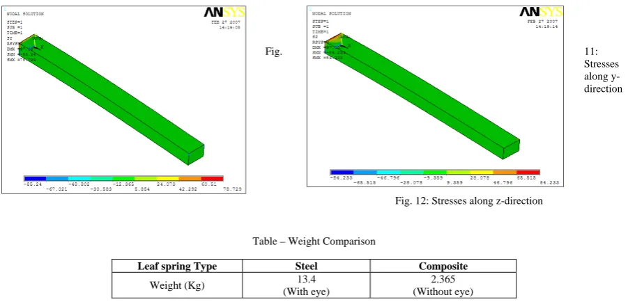
Fig. 11: Stresses
along y-direction
Fig. 12: Stresses along z-direction
Table – Weight Comparison
7. Result and Discussion
The performance of existing steel leaf spring was compared with the fabricated composite leaf spring. Testing has been done for unidirectional E-Glass/Epoxy mono composite leaf spring. Since the composite leaf spring is able to withstand the static load, it is concluded that there is no objection from strength point of view also, in the process of replacing the conventional leaf spring by composite leaf spring. Since, the composite spring is designed for same stiffness as that of steel leaf spring, both the springs are considered to be almost equal in vehicle stability. The major disadvantages of composite leaf spring are sometimes breaking of fibers. When composite leaf spring hit by stone then there is chances of breaking of fibers. This may result in a loss of capability to flexural stiffness. But this depends on the condition of the road. In normal road condition, this type of problem will not occur.
8. Conclusion
Experimental results from testing the leaf springs under static loading containing the stresses and deflection are calculated. These results are also compared with FEA. The weight of the leaf spring is reduced considerably about 85 % by replacing steel leaf spring with composite leaf spring. Thus, the objective of reducing the unsprung mass is achieved to a some extent. Also, the stresses in the composite leaf spring are much lower than that of the steel spring.
Acknowledgement
The author wish to express their sincere thanks to the Head of Mech Engg dept for their support and encouragement to do work. Also, they are very much thankful to Dr. Mohite IIT Kanpur for his valuable suggestions.
References
[1] Al-Quershi HA. Automobile leaf springs from composite materials. J Mater Process Technology 2001; 108:58–61 [2] Beardmore,P.(1986). Composite structure for automobiles. Composite Structure,5(3),163-176
[3] Rajendran,I.,&Vijayarangan,S.(2001). Optimal design of a composite leaf spring using genetic algorithms. Computer & Structure, 79
(11) , 1121-1129
[4] Mallick PK. Composite engineering handbook. New York: Marcel Dekker; 1997.
[5] Sardou A, Patricia D. Light and low cost composite compression C springs for vehicle suspension. SAE 2000:2000-01–2000-0100. [6] Shokrieh M, Rezaei D. Analysis and optimization of composite leaf spring.
Compos Struct 2003; 60:317–25.
[7] Tanabe K., Seino T., Kajio Y., Characteristics of carbon/glass fiber reinforced plastic leaf spring. Society of Automotive Engineers, Inc. 820403; 1982.
[8] Watanabe K., Tamura M., Yamaya K, Kunoh T. Development of a new-type suspension spring for rally cars. J Mater Process Technology 2001; 111:132-4.
Leaf spring Type Steel Composite
Weight (Kg) 13.4
(With eye)