Mitigation of Harmonics by Shunt Active Power
Filter using Synchronous Detection Method
A.Subramaniya Siva #1, M.Bhavani *2
#
Electrical and Electronics Engineering,
Anna University Chennai/Anna University Regional Centre Madurai/PG Scholar, Madurai, Tamilnadu, India
#
Electrical and Electronics Engineering,
Anna University Chennai/Anna University Regional Centre Madurai/Assistant Professor, Madurai, Tamilnadu, India
Abstract— In recent days the usage of non-linear loads are becoming enormous which gives an alarming signal to power system and power engineers. This paper deals with design, simulation experimentation of a shunt active power filter (SAPF)
to improve power quality. Due to a large amount of non-linear
power electronic equipments, and fluctuating loads (such as that of arc furnace, heavy merchant mill etc), problems of power quality have become more and more serious with each passing day. The usage of active filter mitigates the harmonics present in the current signal resulting in maintaining the quality of the power supply in the system. It is known from the fact that Harmonic Distortion is one of the main power quality problems frequently encountered by the utilities. As a result Shunt Active power filter (SAPF) gains much more attention due to excellent harmonic compensation. Here Synchronous Detection Method (SDM) is used to tune the Shunt active power filter. On owing SDM method gives away an outstanding performance under any voltage conditions (balanced, un-balanced, balanced non sinusoidal and balanced sinusoidal). Extensive simulations were carried out; Simulation results validate the superior performance of Synchronous Detection method (SDM). Simulation is done in Matlab/simulink software and the results shows that Total Harmonic Distortion (THD) is reduced significantly when compared with other methods.
Index Terms— Harmonic compensation, Shunt Active power filter, hysteresis controller, IGBT, SDM control strategy.
I.INTRODUCTION
Many social and economic activities depend on electrical energy quality and efficiency. Both industrial and commercial users are interested in guaranteeing the electrical waveform quality, which supplies their different systems. The nonlinear load can generate current harmonics and/or voltage harmonics, which makes worse the power quality. Therefore, these harmonics must be mitigating. In order to achieve this, series or parallel configurations or combinations of active and passive filters have been proposed depending on the application type. Traditionally, a passive LC power filter is used to eliminate current harmonics when it is connected in parallel with the load. This compensation equipment has some drawbacks mainly related to the appearance of series or
parallel resonances because of which the passive filter cannot provide a complete solution.
In recent years, single-phase electronic equipments have been widely used in domestic, educational and commercial appliances. These equipments include computers, communication equipments, electronic lighting ballasts etc. Also, a large number of computers are turned on at the same time. Each computer and its related devices have a diode rectifier to convert AC electricity to DC one. In other words, those equipments draw non-sinusoidal currents which pollute the utility line due to the current harmonics generated by the nonlinear loads. [1] [5]
Since the beginning of the 1980s, active power filters (APFs) have become one of the most habitual compensation methods. The APF can be connected either in parallel or in series with the load. The shunt connection APF is the most studied topology. However, the costs of shunt active filters are relatively high for large-scale system and are difficult to use in high-voltage grids.[7] In addition, their compensating performance is better in the harmonic current source load type than in the harmonic voltage source load type. The first of these proposed by Akagi also known as Instantaneous P-Q-theory can be effective only when the supply voltages are balanced. [9]
Two main categories of APFs exist: shunt filters, also called parallel filters, and series filters. [2][3] The former are effective for those nonlinear loads, which can be considered as current harmonic sources (e.g., phase-controlled rectifiers with large dc inductance). Shunt filters are therefore used to generate harmonic currents to compensate load harmonic currents. Series filters are effective to generate harmonic voltages to compensate load harmonic voltages. This paper deals with shunt filters. [11]
addressed by the APF controller, from which three control strategies derive:
1) Constant instantaneous source power control; 2) Sinusoidal current control;
3) Generalized Fryze current control.
This paper describes the principle of synchronous detection method (SDM). This technique is suitable only for three-phase system and its operation relies in the fact that the three-phase currents are balanced. [4] [6] It is based on the idea that the APF forces the source current to be sinusoidal and in phase with the source voltage despite the load variations. [8][10] This improved method is simulated, and the real-time and accuracy of this method is proved.
II. OVERVIEW OF ACTIVE POWER FILTER
To cancel the harmonics and compensate the reactive power APF is the suitable solution. The APF concept is to use an inverter to inject currents or voltages harmonic components to cancel the load harmonic components. The more usual configuration is a shunt APF to inject current harmonics into the point of common coupling (PCC). The APF can be installed in a low voltage power system to compensate one or more loads; thus, it avoids the propagation of current harmonics in the system. The developments of different control strategies give APF to a new location. As APF compensate the reactive power and cancel the harmonics, it is also called as active power line conditioners (APLC). The three main aspects of an active power conditioner are:
The configuration of power converter (the scheme and the topology of converter and the electronics device used)
The control strategy (the calculation of APLC control reference signals)
The control method used (how the power inverter follows the control reference).
The topology of active power filter is classified into three types.
Series active power filters
Shunt active power filters
Hybrid active power filters.
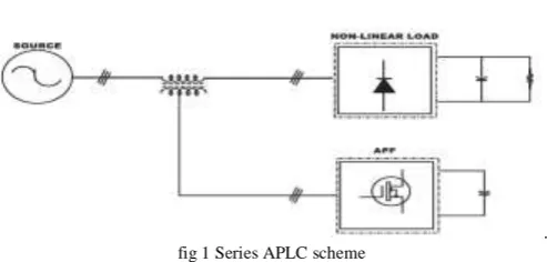
. fig 1 Series APLC scheme
The connection scheme of a series APLC is as shown in the following diagram. It is connected to the power system
through coupling transformer. The compensation voltage is used to cancel the voltage harmonics of load.
Fig.2 Shunt APLC scheme
The three-phase shunt active power filter is a three-phase current controlled “voltage source inverter” (CC-VSI) with a mid-point earthed, split capacitor in the dc bus and inductors in the ac output.
Conventionally, a shunt APF is controlled in such a way as to inject harmonic and reactive compensation currents based on calculated reference currents. The injected currents are meant to “cancel” the harmonic and reactive currents drawn by the non-linear loads. However, the reference or desired current to be injected must be determined by extensive calculations with inherent delays, errors and slow transient response.
A key component of this system is the added series inductance XL which is comparable in size to the effective grid
impedance, ZS. Without this inductance (or a series active
filter), load harmonic voltage sources would produce harmonic currents through the grid impedance, which could not be compensated by a shunt APF. Currents from the APF do not significantly change the harmonic voltage at the loads. Therefore, there are still harmonic voltages across the grid impedance, which continue to produce harmonic currents.
The grid current is sensed and directly controlled to follow symmetrical sinusoidal reference signals in phase with the grid voltage. Hence, by putting the current sensors on the grid side, the grid current is forced to behave as a sinusoidal current source and the grid appears as a high-impedance circuit for harmonics. By forcing the grid current to be sinusoidal, the APF automatically provides the harmonic, reactive, negative and zero sequence currents for the load, following the basic current summation rule:
i
GRID
i
APF
i
LOAD (1)The sinusoidal grid current reference signal is given by:
i
REF
kv
GRID
1
(2)where vgrid-1 is the fundamental component of the grid voltage, and k is obtained from an outer control loop regulating the CC-VSI dc-bus voltage.
This paper presents a new detection method called Synchronous Detection Method (SDM). It has been applied to a shunt active power filter the following assumptions are made in calculating the three phase compensating currents using equal current distribution method of synchronous detection algorithm. The basic idea is forming rotating coordinate by using virtual symmetrical three-phase system synthetic voltage vector system. This method does not need PLL, so it eliminates the adverse effects generated by PLL. Here we assume that
Voltage is not distorted.
Loss in the neutral line is negligible.
The three phase main currents are assumed to be balanced after compensation in this method and also try to determine the required amplitude of the source currents. Let the instantaneous load currents be ia(t),ib(t),ic(t) and their corresponding phase voltage be va(t),vb(t),vc(t) are shown in the fig1.the real power P(t) is calculated as below.
)]
(
)
(
)
(
[
)]
(
)
(
)
(
[
)
(
t
v
t
v
t
v
t
i
t
i
b
i
c
P
a b c
a (3)Therefore the average value Pdc can be determined by applying P(t) to a low pass filter. Thus, the real power is split into three phases, they are
]
[
am bm cmam dc
a
v
v
v
v
P
P
(4)
]
[
am bm cmbm dc
b
v
v
v
v
P
P
(5)
]
[
am bm cmcm dc
c
v
v
v
v
P
P
(6)
Where vam, vbm and vcm are the amplitudes of va(t),vb(t) and vc(t) respectively. Thus the balanced current can be determined as, 2
)
2
(
am a a sav
P
v
i
(7)2
)
2
(
bm b b sbv
P
v
i
(8)2
)
2
(
cm c c scv
P
v
i
(9)The compensation current references are thus,
a sa
ca
i
i
i
(10)b sb
cb
i
i
i
(11)The compensation currents ica*, icb*, icc* are fed to the CSI which supplies the exact replica of harmonic currents so that they are cancelled out and pure sinusoidal current are fed to the source. Since the CSI is assumed to be instantaneous to track the compensation currents, it is modeled as a current
amplifier with unity gain. This method can be extensively used for compensation of reactive power, current imbalance and mitigation of current harmonics. It is the simplest method as it requires minimum calculations.
Source Non
linear load SDM algorithm block IGBT block Hysteresis block
SDM FILTER BLOCK
Fig.3 SAPF tuned with SDM method
This method can be extensively used for compensation of reactive power, current imbalance and mitigation of current harmonics. It is the simplest method as it requires minimum calculations.
The SDM method is designed in such a way that it consists of three phase source connected to the three phase nonlinear load (universal bridge rectifier) with a RL circuit. In between these components, the average power determination block (needed for the function of SDM) and shunt active power filter is connected. This average power determination block and filter blocks are different blocks which incorporated to perform different operations and finally produce compensation current and inject it into the transmission line.
The three phase current and voltage are allowed into Average power determination block. At first the instantaneous real power P(T) (3) consumed by the load is calculated and from the product of corresponding instantaneous voltages and load currents of each phase are summing up by the values of all the three phases. Then it is passed to the zero order hold block and mean value detector block so that the average power Pdc is calculated for each phase. Then the average power obtained is fed into the filter circuitry for the generation of compensation currents. The filter circuitry consists of following blocks shown in fig 3:
SDM algorithm block.
Hysteresis control algorithm block. IGBT gating pulse circuit.
equation 7, 8, 9. Then the difference between the reference line currents for each phase (I*sa, I*sb, I*sc) and Load currents (Ia, Ib, Ic) is calculated which yields the compensation current which is going to be injected in the line. The compensation current thus obtained is fed into the hysteresis control block Thus the currents (i*fa, ifa), (i*fb, ifb),(i*fc, ifc) are compared with a comparator before which the currents i*fa, i*fb, i*fc are added with a constant value of 1 and IGBT currents of ifa, ifb, ifc are subtracted from the same constant value of 1. The compared value is allowed to process through a SR flip-flop whose initial condition that is the state of Q is assigned with a value of 1.The processed output of each SR flip-flop of each phase (Q, ) is allowed for the unit delay which produces the Pulsating signals (G1,G2,G3,G4,G5,G6) for triggering the GTO present in the IGBT gating pulse circuit.
IV.SIMULATIONRESULTS
The shunt active power filter which is connected to a voltage source type non-linear load is simulated by using MATLAB/SIMULINK environment. The scheme is first simulated without any filter to find out the THD of the supply current. Then it is simulated with the filter tuned with SDM method to observe the difference in THD of supply current. Simulation is also carried out with hysteresis controller and to find out the comparative study of the THD of the supply current.
Fig 4 Nonlinear load voltage waveform
Fig.5 Source Current Waveform before filtering
Fig.6 Source Voltage Waveform before Filtering
Fig.7 Load Current Waveform before Filtering
Fig.8 Load Voltage Waveform before Filtering
Fig.9 Source Current Waveform after Filtering
V
o
lt
a
g
e
(V
)
Time (s)
Time (s)
Cu
rre
n
t
(A
)
V
o
lt
a
g
e
(
V
)
Time (s)
Cu
rre
n
t
(A
)
Time (s)
Time (s)
V
o
lt
a
g
e
(V
)
Time (s)
Cu
rre
n
t
(A
Fig.10 Generated Compensating Current Waveform
Fig.11 THD on Source Side
V. CONCLUSION
In this work Synchronous Detection Method (SDM) control strategies is developed and verified with three phase four wire system. It is observed that SDM method gives always better results under un-balanced & non-sinusoidal voltage conditions over other methods. In this method, angle „θ‟ is calculated directly from main voltages & thus enables the method to be frequency independent. Thus large number of synchronization problems with un-balanced and non-sinusoidal voltages is also avoided. By using this method the source side THD is reduced from 29% to 0.91%.
VI.REFERENCES
1. Yi Tang, Student Member, IEEE, Poh Chiang Loh, IEEE,Peng Wang, Member,IEEE, Fook Hoong Choo, Feng Gao, Member, IEEE, & Frede Blaabjerg, Fellow, IEEE “ Generalised Design Of High Performance Shunt
Active Power Filter With Output LCL Filter”IEEE Trans on Industrial Electronics, Vol.59,NO.3,March 2012
2. Maurizio Cirrincione, Member IEEE, Marcello Pucci,Member IEEE, Gianpaolo Vitale, Member IEEE, & Abdellatif Miraoui, Member, IEEE, “Current Harmonic
Compensation by a Single-Phase Shunt Active Power Filter Controlled By Adaptive Neural Filtering” IEEE Trans on Industrial Electronics, Vol,56.NO.8, AUG 2009.
3. Md. Ashfanoor Kabir and Upal Mahbub “Synchronous
Detection and Digital control of Shunt Active Power Filter in Power Quality Improvement” Bangladesh University of Engineering IEEE Transactions 2011.
4. Patricio Salmeron & Reyes S. Herrera “Distorted & Unbalanced System Compensation Within Instantaneous Reactive Power Framework” IEEE Trans. On Power Delivery.Vol.21,NO.
5. Izzeldin Idris abdalla, K.S.Rama Rao, N.Perumal “Three Phase Four- Leg Shunt Active Power Filter to Compensate harmonics & Reactive Power” 2011 IEEE Symposium on Computer & Informatics.
6. Chennai Salim & Benchouia Mohamed Toufik IEEE Member “Intelligent Controllers for Shunt Active Filter to
Compensate Current Harmonics Based on SRF and SCR Control Strategies” International Journel on Electrical Engg & Informatics Vol 3, 2011.
7. Hirofumi Akagi, Yoshihira Kanazawa and Akira Nabae,
“Instantaneous reactive power compensator comprising switching power devices without energy storage components,” IEEE Transactions on Industry Applications, Vol. 1A-20, May/June 1984, pp.
8. M. F. Shousha*, Student Member, IEEE, S. A. Zaid*, and O. A. Mahgoub*, Member, IEEE “ Better Performance for Shunt Active Power Filters” Electrical Power and Machines Department, Cairo University, (Egypt) IEEE Transactions 2011.
9. Patricio Salmeron and Salvador P. Litran “A Control
Strategy for Hybrid Power Filter to Compensate Four-Wires Three-Phase Systems” IEEE Transactions on Power Electronics, vol. 25, no. 7, july 2010.
10. Hu Yong-jun ,Fan Li-li, Hu Ya-jing “A Reactive and Harmonic Current Detection Method of Three-phase Asymmetric System” 2010 International Conference on Computational and Information Sciences.
11. Moleykutty George and Kartik Prasad Basu “Performance Comparison of Three-Phase Shunt Active Power Filter Algorithms”American Journal of Applied Sciences 5 (11): 1424-1428, 2008 ISSN 1546-9239 © 2008 Science Publications
Cu
rre
n
t
(A
)