933
A New Droop Compensated CIC Decimation Filter
With Improved Response
Gaganjot kaur, Sanjay sharma
ABSTRACT:This paper extends the class of sharpened modified comb filter(SMCF) introduced by Missimilano Laddomada for ∑∆ A/D converters in order to obtain more improved response i.e., lesser pass band droop than SMCF and alias rejection better than basic CIC with the use of compensation techniques along with SMCFs. Sine based compensation and the maximally flat compensation are applied to SMCF by Laddomada for achieving improved results. The overall response improvement is targeted in this paper. Zero droop in pass band and better alias rejection is achieved for SMCFs which is shown with the help of computer simulations.
Index Terms—CIC filter;SMCF; Compensation
————————————————————
1.
INTRODUCTION
Hogenauer [1] proposed a CIC(cascaded integrator comb) filter, a class of FIR(finite impulse response) filter having linear phase for decimation and interpolation, which require no multiplier that is use limited storage making them a feasible alternate in the conventional implementation for certain applications. These comb filter structures are basically based on moving average filter. The filter characteristics are managed by three parameters, which are number of stages, the differential delay and the number of bits in input/output registers.The CIC filters are multiplication free filters with limited storage requirements, which make them ideal for the high speed data converters. Hogenauer [1] presented an FIR structure, which consists of cascaded integrator stages working at the higher sampling rate and the same number of comb stages working at the low sampling rate. A number of cascaded integrator comb pairs are chosen to meet the design requirements for aliasing or imaging errors. Although, the CIC filters can implement decimation and interpolation efficiently in the hardware for a wide range of rate change factors, yet CIC filter response is lacking in a flat pass-band response and better transition bandwidth. The decimation filter proposed by Hogenauer [1] is a class of linear phase finite impulse response (FIR) filter which performs sampling rate conversion with the use of only adder/subtractor. The transfer function of filter is given by
(1)
( )=[ ( )
( )] (2)
Nulls occur at 1/N andNth null is folded into passband to give folding bands from - fc to + fc where fc is edge of useful band or the normalized maximum frequency. Its characteristics suffer from high passband droop which is dependent on decimation factor N and the cascade size K and also have low attenuation in stopband.Various techniques have been proposed to deal with problems in response of CIC filters. Earlier sharpening techniques were used to improve the response [2],[3],[4]. L. Presti presented an attractive modification to improve stopband of filter for ∑∆ A/D converters [5]and it was further extended by Laddomada [6], [7]. Apart from sharpening, method to design second order compensation filter is given in [8] which is a pass band improvement technique. This technique was extended in [9],[10],[11] and was also applied with previous techniques to achieve better results[12]. Kaiser and Hamming [2] presented a method of filter sharpening for symmetric non recursive filter. Filter sharpening is to make the filter response better. Better means less pass band error and more out of band attenuation. The main approach is to process the datathrough samefilter repeatedly but while eachpass increases the stop band attenuation but also increases the pass band error.to undesirable level. The length (order) of filter of the equivalent filter also gets increased. It showed how to connect multiple instances of same filter to get better response. The method he described was based on amplitude change function or polynomial which is restricted
to.symmetric non-recursive FIR filter.with piecewise
constant.passband and stopband. The proposed
polynomial is one which passes through point (0,0) and (1,1) and has nth order tangency at zero and mth order tangency at unity. It means the curve of amplitude change was tangent horizontally at both zero and unity. Hence giving more flat area.
1.1 Sharpened modified comb filter
Laddomada [6] used the two stage.architecture and
employed modified sinc filter by Presti i.e. the one obtained by optimal.rotation of zeros at.first stage and sharpening at second stage to get class of sharpenedmodified comb filter (SMCF) which to aimed to increase the quantization.noise rejection around folding bands with the simultaneous
improvement in passband droop.compared to
conventional.comb filter. The main focus was given to
equivalent third order modified sinc filter with which
noise.suppression of 8db was achieved compared to
————————————————
Gaganjot Kaur,Assistant Professor in Electronics and
Communication Engineering Department inChandigarh University, Mohali,India. E-mail: [email protected]
934
classic third order filter. SMCF is one of technique for response improvement of ∑∆ A/D converters [6]. Different order MCFs (Modified Comb Filter) are proposed [6] which are based on technique given by L. Presti [5] which uses concept of rotation of nulls in z plane so as to guarantee the best noise suppression(∑∆ quantization noise) around folding band applied to comb filter section and then the sharpening technique is applied to it to obtain SMCF. The second order transfer function obtained by rotation of nulls [5] is
( ) ( ) ( ) (3)
( )has real coefficients and linear phase . The frequency
response corresponding to (3) is
( ) ( ) ( ) ( ) ( ) ( ) (4)
It has nulls at frequencies ± , where i is an integer and α
is chosen to cover folding band ± fc with rotated zeros and
is having value 2qπfc with q<1.
Third order MCF is obtained by multiplication of first order comb filter (1) with second order filter (3).
HMCF3(f) = HCIC(f). Hr(f)
HMCF3(f) =
( )
( )
( ) (5a)
Similarly forth order MCF by multiplication of second order comb with second order filter in (3)
HMCF4(f) = HCIC 2(f). Hr(f) (5b)
HMCF5(f) = HCIC(f). Hr1(f) ). Hr2(f) (5c)
HMCF6(f)=HCIC2(f).Hr1(f).Hr2(f) (5d)
The values of r1 and r2 are calculated in[6] for ∑∆ A/D converters so as to obtain extra noise suppression of ∑∆QN noise around folding band. Then the sharpening [2] is applied to MCF to obtain SMCF with improved response. We have a family of sharpened filter
(f)= (f)∑ ( ) ( ) (6)
Where H is a basic filter, m and l represent number of
nonzero derivatives of (f) at points where (f) = 0 and
(f) =1. The class of SMCF [6] is written as:
For m= l=1
H11 (f) = HCIC 2(f). Hr1(f).[3 ( )-HCIC 2(f)] (7a)
m=1, l=2
H12(f) = HCIC 2(f). Hr1(f).[6 ( ) 8 ( )HCIC2(f) + 3 ( ) ]
(7b)
m=2 , l=1
H21(f) = HCIC 2(f). Hr1(f) ). Hr2(f). [4 ( ) - 2HCIC 2(f)] (7c)
m=2 , l=2
H22(f) = HCIC 2(f). Hr1(f) ). Hr2(f).[10 ( ) 15 ( )HCIC 2(f) +
6 ( ) ] (7d)
Where ( ) are to equalize the group delay in various filter branches.Laddomada [7] proposed two stage architecture. The first stage consists of conventional.comb decimator
and second stage a sharpened.comb decimator. The main
advantage of using this was that sharpened section now operated at lower rate by the first stage decimation factor and also poly-phase.decomposition can be used at first section. This structure has much better aliasing rejection than conventional one and even sharpened comb. The passband droop was however similar to original sharpened but smaller than conventional one.
1.2 Compensation
Dolecek and Mitra [8] presented a simple second order sine based CIC. Depending on the number of stage K, there is only one design parameter which again depends on
whether compensation is narrow band.or wideband.
Sine based compensation [8] is given as
|G ( )| = |1+ (ωN/2)| (8) Using relation
(α) = (1-cos2α)/2
Corresponding transfer function is given as
G( )= ( ) ( ( ) ) ] (9a) or
G( ) =A ] (9b) A= ( ) and B=-( ( ) )
Where r is an integer value and can be chosen as design parameter. A simple MATLAB program is used to find value of r [8] given in Table 1.
Table 1 Values of Parameter r
K parameter r
2,3 2
4 1
5,6 0
1.3 Maximally flat compensation
Vanquez and Dolecek [9] introduced design and
implementation of maximal flat CIC.compensation filter.
Closed form equation is given for computation of filter.coefficients for second and fourth order filter for narrow
band and wide band compensation. However
compensation.filter does not adverse the attenuation in aliasing band of CIC filter Compensation technique given by A. Fernandez[9] and extended in [10] gives the transfer function R(z) as
( )= a+ (10)
935
a = ( ( )) (10a) a= - .
Where, C = ( ( ))
Romero and Laddomada [13] presented optimal sharpening of compensated comb filter. They showed that compensated filter or sharpening compensated CIC filter needs low degree.sharpening polynomial in comparison to
sharpened.CIC filter without compensation as far as
magnitude.specifications are concerned. It all resulted in
complex solution. The results showed the great
performance.improvement in passband droop and
selectivity as compared to other traditional methods. Dolecek[14] presented an multiplier less representation of comb filter. It increased the stopband without affecting the passband. It is done with cascade of modified comb in first stage and second stage includes variable length comb filters and additional zeros in folded band.
2.
PROPOSED DESIGN
To further improve the response we apply the
compensation which is used to improve pass band in cascade with SMCF so as to achieve overall lesser pass band droop while significant increase in stop band attenuation over basic CIC. So the overall improvement over basic CIC is proposed
Applying compensation (9) in cascade with SMCF H11(f) (7a)we get
HCB11(f) = H11(f) . G( )
HCB11(f) = ( )HCIC 2(f). Hr1(f).[3 ( )-HCIC 2(f)].
( ( ) ) ]
HCB11(f) = A. HCIC 2(f). Hr1(f).[3 ( )-HCIC 2(f)].
] (11a)
WhereA= ( )and B=-( ( ) ) Similarly for other SMCFs we get
HCB12(f) = HCIC 2(f). Hr1(f).[6 ( ) 8 ( )HCIC2(f) + 3 ( ) ].A ] (11b)
HCB21(f) = HCIC 2(f). Hr1(f) ). Hr2(f). [4 ( ) - 2HCIC 2(f)].A
] (11c)
HCB22(f) = HCIC 2(f). Hr1(f) ). Hr2(f).[10 ( ) 15 ( )HCIC 2(f) + 6 ( ) ] .A ] (11d)
Applying maximally flat compensation (10) in cascade with SMCF we get
HCM11(f) = H11(f) . R( )
HCM11(f) = HCIC 2(f). Hr1(f).[3 ( )-HCIC 2(f)]. ] (12a)
Where the coefficients a and b are given in equation (10b)
a = ( ( )) b = 1-2a
Similarly for other SMCFs
HCM12(f) = HCIC 2(f). Hr1(f).[6 ( ) 8 ( )HCIC2(f) + 3 ( ) ]. ] (12b)
HCB21(f) = HCIC 2(f). Hr1(f) ). Hr2(f). [4 ( ) - 2HCIC 2(f)].
] (12c)
HCB22(f) = HCIC 2(f). Hr1(f) ). Hr2(f).[10 ( ) 15 ( )HCIC 2(f) + 6 ( ) ] . ] (12d)
3.
RESULTS AND DISCUSSIONSHere are the results which we obtain by cascade of compensation with SMCF and also the comparison with SMCF.
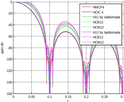
Fig. 1(a) and 2(a) shows the overall magnitude response for SMCF H11 ,H12 and SMCF H21, H22 by Laddomada and also cascade of them with two compensation techniques respectively for N=10 and their comparison.
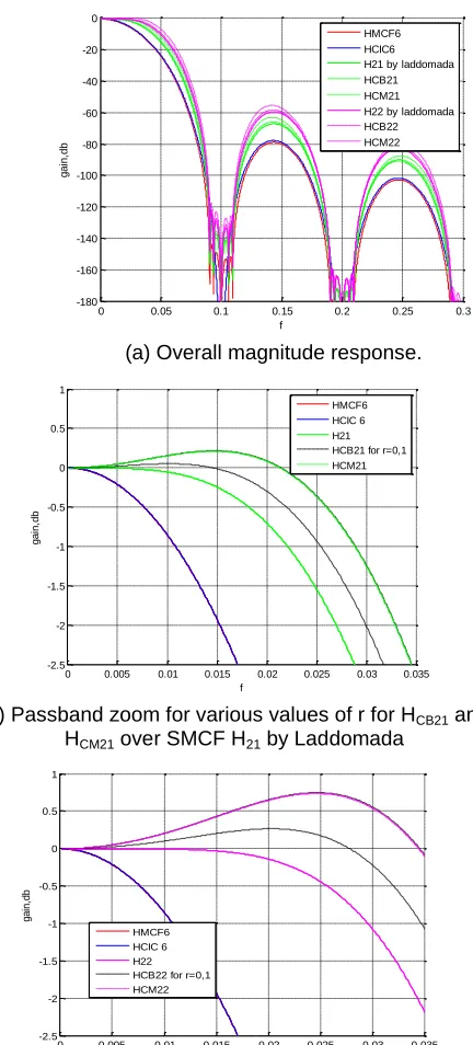
Fig. 1(b) and 2(b) shows the zoom in view for HCB11 and HCB21 respectively. We can observe for HCB11 that at cut off frequency fc = 0.01 the droop is zero for r=2 while SMCF H11 is giving that of 0.06 dB. It is much greater for classic comb filter and MCF both overlapping as shown in fig nearly 0.57db. While for r=1, there is a gain of 0.07 db. HCM11 shows gain of 0.04db. In Fig. 2(a) for HCB21 at fc=0.01, droop is zero (slight gain 0.05) for HCB12 for r= 1, while for SMCF it is 0.02 dB and there is a gain of 0.15db for r=0 and HCM12. So with use of r=2 for H11 and r= 1 for H21 we are achieving zero droop at the cut off frequency.
(a). Overall magnitude response
0 0.05 0.1 0.15 0.2 0.25 0.3
-160 -140 -120 -100 -80 -60 -40 -20 0
f
g
a
in
,d
b
936 (b). Passband zoom for r = 1 and 2(top to bottom)for
HCB11 and HCM11 over SMCF H11 by Laddomada
(c).Passband zoom view for r = 1 and 2 (top to bottom) for
HCB12 and HCM12 over SMCF H12 by Laddomada
(d). Stopband Zoom showing high attenuation around nulls
compared to basic Comb filter.
Fig. 1. Frequency response of filter H11 and H12 by Laddomada after cascade with sine based compensation and max flat compensation for N =10, K=4, r=1,2 and
q=0.85 and fc=0.01.
Fig. 1(c) and 2(c) shows the zoom in pass band response for HCB12 and HCB22 respectively. HCB12 gives slight gain of 0.05db for r=2 and 0.1for r=1 while there is a gain 0.14 dB
for HCM12. Similarly for HCB22 at fc=0.01, droop is 0.01db for H22 and there is gain of 0.1db for r=1 and 0.2db for r=0 and HCM22.
So it is clear that that the roll off response presented by CIC in passband is reduced with SMCF and now further with compensated SMCF and results are confirmed by the figures.
The alias rejection in the stop band of CIC is also improved with L. Presti technique [5]. Fig 1(d) and 2(d) shows the stop band response. Folding bands are centred around i/N and cover the range from to .As it is clear that stop band has improved significantly over the classic comb filer.So overall lesser passband droop and more alias rejection is achieved through the use of compensated SMCFs as shown.
(a) Overall magnitude response.
(b) Passband zoom for various values of r for HCB21 and HCM21 over SMCF H21 by Laddomada
(c). Passband zoom for various values of r for HCB22 and HCM22 over SMCF H22 by Laddomada
0 0.005 0.01 0.015 0.02 0.025 0.03 0.035
-2.5 -2 -1.5 -1 -0.5 0 0.5 1
f
g
a
in
,d
b
HMCF4 HCIC 4 H11 HCB11 for r=1,2 HCM11
0 0.005 0.01 0.015 0.02 0.025 0.03 0.035
-2.5 -2 -1.5 -1 -0.5 0 0.5 1
f
g
a
in
,d
b
HMCF4 HCIC 4 H12 HCB12 for r=1,2 HCM12
0.085 0.09 0.095 0.1 0.105 0.11 0.115
-160 -150 -140 -130 -120 -110 -100 -90 -80 -70 -60
f
g
a
in
,d
b
HMCF4 HCIC 4 H11 by laddomada HCB12 HCM12 H12 by laddomada HCB12 HCM12
0 0.05 0.1 0.15 0.2 0.25 0.3
-180 -160 -140 -120 -100 -80 -60 -40 -20 0
f
g
a
in
,d
b
HMCF6 HCIC6 H21 by laddomada HCB21 HCM21 H22 by laddomada HCB22 HCM22
0 0.005 0.01 0.015 0.02 0.025 0.03 0.035
-2.5 -2 -1.5 -1 -0.5 0 0.5 1
f
g
a
in
,d
b
HMCF6 HCIC 6 H21 HCB21 for r=0,1 HCM21
0 0.005 0.01 0.015 0.02 0.025 0.03 0.035
-2.5 -2 -1.5 -1 -0.5 0 0.5 1
f
g
a
in
,d
b
937
(d). Stopband zoom showing high attenuation around nulls compared to basic Comb filter.
Fig.2. Frequency response of filter H21 and H22 by Laddomada after cascade with sine based compensation and max flat compensation for N =10,K=4, r=0, 1 and
q1=0.64 and q2= 0.94.
4.
CONCLUSION
This paper is focusing on novel decimation filters, it shows better performance in terms of passband drop, quantization noise rejection compared to conventional comb decimation filter.
In Particular this paper has targeted on overall response improvement of Comb filter. The main focus is on further reduction of passband droop of SMCFs by Laddomada with the application of compensation techniques i.e. sine based compensation by G. J. Dolecek and the maximally flat compensation. Comparisons of proposed technique with already existing results are presented in this paper. With the use sine based compensation with r=2 for SMCF H11 (HCB11) and r= 1 for H21 (HCB21) we are achieving zero droop at the cut off frequency while some gain is obtained for H12 and H22.
References
[1] E. B. Hogenauer, ―An Economical Class of Digital
Filters for Decimation and Interpolation,‖ IEEE Trans. Acoust., vol. 29, no. 2, pp. 155–162, 1981.
[2] R. W. Hamming, ―Sharpening the Response of a
Symmetric Nonrecursive Filter by Multiple Use of the Same Filter,‖ IEEE Trans. Acoust., vol. 25, no. 5, pp. 415–422, 1977.
[3] A. Y. Kwentus, Z. Jiang, and A. N. Willson,
―Application of filter sharpening to cascaded integrator-comb decimation filters,‖ IEEE Trans. Signal Process., vol. 45, no. 2, pp. 457–467, 1997.
[4] G. Jovanovic-Dolecek and S. K. Mitra, ―A new
two-stage sharpened comb decimator,‖ IEEE Trans. Circuits Syst. I Regul. Pap., vol. 52, no. 7, pp. 1414–1420, 2005.
[5] L. Lo Presti, ―Efficient Modified-Sinc Filters for
Sigma – Delta A / D Converters,‖ vol. 47, no. 11, pp. 1204–1213, 2000.
[6] M. Laddomada and S. J, ―Comb-based decimation
filters for ∑Δ A/D converters: Novel schemes and comparisons,‖ IEEE Trans. Signal Process., vol. 55, no. 5 I, pp. 1769–1779, 2007.
[7] M. Laddomada, ―Generalized comb decimation
filters for ∑Δ A/D converters: Analysis and design,‖ IEEE Trans. Circuits Syst. I Regul. Pap., vol. 54, no. 5, pp. 994–1005, 2007.
[8] G. J. Dolecek & S. K. Mitra , "Simple method for compensation of CIC decimation filter", Electron. Lett. vol. 44, pp. 1162-1163, 2008.
[9] A. Fernandez-Vazquez and G. J. Dolecek, ―A
general method to design GCF compensation filter,‖ IEEE Trans. Circuits Syst. II Express Briefs, vol. 56, no. 5, pp. 409–413, 2009.
[10] A. Fernandez-Vazquez and G. J. Dolecek,
―Maximally flat CIC compensation filter: Design and multiplierless implementation,‖ IEEE Trans. Circuits Syst. II Express Briefs, vol. 59, no. 2, pp. 113–117, 2012.
[11] V. Lila Haresh and C. S. Vinitha, ―Maximally flat compensated-comb decimation filter with filter sharpening technique,‖ Proc. 2014 Int. Conf. Adv. Comput. Commun. Informatics, ICACCI 2014, no. 2, pp. 2411–2416, 2014.
[12] G. J. Dolecek and F. Hams, ―Design of CIC
compensator filter in a digital if recevier,‖ 2008 Int. Symp. Commun. Inf. Technol. Isc. 2008, vol. 2, pp. 638–643, 2008.
[13] D. E. Troncoso Romero, M. Laddomada, and G.
Jovanovic Dolecek, ―Optimal Sharpening of Compensated Comb Decimation Filters: Analysis and Design,‖ Sci. World J., vol. 2014, no. 1, pp. 1–9, 2014.
[14] G. J. Dolecek, ―Comb Aliasing Rejection
Improvement Using Modified Combs and Combs of Different Lengths,‖ Int. Conf. Digit. Signal Process. DSP, vol. 2018–Novem, no. 1, pp. 1–5, 2019.
Abbreviations
CIC – Cascaded Integrator Comb SMFC – Sharpened Modified Comb Filter FIR - Finite impulse response
A/D – Analog to Digital QN – Quantization Noise ∑∆ - Sigma Delta
0.085 0.09 0.095 0.1 0.105 0.11 0.115
-180 -160 -140 -120 -100 -80 -60
f
g
a
in
,d
b