TRINITY COLLEGE DUBLIN
COLÁISTE NA TRÍONÓIDE, BAILE ÁTHA CLIATH
MODELLING PROGRESSIVE COLLAPSE IN STEEL
STRUCTURES
V
ICTORIAM
ARIAJ
ANSSENSB.A. B.A.I., PGDip.Stat.
A Thesis submitted in fulfilment
of the requirements for the Degree of
Doctor of Philosophy
March 2012
Supervisor: Dr D O’Dwyer
The Department of Civil, Structural and Environmental Engineering
D
ECLARATIONI declare that this thesis has not been submitted as an exercise for a degree at this or any other university and it is entirely my own work.
I agree to deposit this thesis in the University’s open access institutional repository or allow the library to do so on my behalf, subject to Irish Copyright Legislation and Trinity College Library conditions of use and acknowledgement.
_______________________
S
UMMARYThe partial collapse of the Ronan Point apartment tower in 1968 was a pivotal event with regard to the way structural engineers considered progressive collapse. This event spurred a significant amount of research into the prevention of disproportionate collapse and prompted the Fifth Amendment to the UK Building Regulations. As a result, the possibility of structural collapse was considered for the first time in a regulatory document. From this point on, buildings were required to exhibit a minimum level of robustness to resist progressive collapse. Following the recent terrorist attacks on the Alfred P Murrah Federal Building, in 1995, and the World Trade Centre, in 2001, interest in this subject appears to have reached a peak. Additionally, these events have highlighted the increased threat of terrorism worldwide and the need to consider hazards (e.g. explosions and detonations) that may not have been viewed as significant in the past.
A collapse of this nature can be triggered by many causes: including design and construction errors, as well as loading conditions with a low probability of occurrence (e.g. gas explosions, vehicular collisions). However, the unforeseen nature of these events presents the designer with a significant challenge when trying to improve structural safety. As building designers cannot possibly design for every hazard that a building may be subjected to in its lifetime, a general design approach is required to account for the risks associated with low-probability high-consequence events. In view of this, a number of design methods to improve structural robustness have been developed that are independent of the loading event: namely, the notional element removal and specific local resistance methods.
The primary objective of this research is to develop an analysis program that is capable of modelling the complex structural behaviour associated with progressive collapse. This program is based on the finite element method of analysis and implements the notional element removal method using three different types of analysis, of increasing complexity: linear static, nonlinear static and nonlinear dynamic analysis. The effects of material nonlinearities are modelled using lumped plastic hinges and geometric nonlinearities are accounted for by regularly updating the structural matrices to include the displaced shape of the structure. In order to compute the time-varying response of the structure following the loss of a member, a fourth order Runge-Kutta routine is implemented. Meanwhile, viscous damping effects are incorporated in the dynamic analysis algorithm using Rayleigh damping theory. A key feature of the program is that it is capable of following the sequence of failures that occur during a progressive collapse. In order to achieve this, all members are periodically checked for failure: this may be due to the formation of an unstable mechanism, instability of a member or exceeding the capacity of a member.
performed, the results of which demonstrate the conservative nature of linear static analysis. Additionally, the importance of dynamic effects when considering progressive collapse is illustrated. Furthermore, an investigation of the influence of damping shows that the level of damping assumed has a notable influence on the response of the structure. This is contrary to the often cited assumption that the effects of damping will be negligible in progressive collapse and therefore raises some interesting research questions.
A
CKNOWLEDGEMENTSI would like to express my gratitude to my supervisor Dr Dermot O’Dwyer for his support and encouragement, as well as his valuable advice and constructive comments.
I also wish to gratefully acknowledge Prof Marios Chryssanthopolous (University of Surrey) for the substantive guidance provided with regard to the work presented in Chapter 6 of this thesis.
I would like to thank the Irish Research Council for Science, Engineering and Technology (IRCSET) for the funding received under their Postgraduate Scholarship Scheme.
T
ABLE OF CONTENTSDeclaration ... ii
Summary ... iii
Acknowledgements ... v
Table of contents ... vi
List of Figures ... x
List of Tables ... xvi
List of Notation ... xviii
List of Abbreviations...xxii
CHAPTER 1INTRODUCTION ... 1
1.1WHAT IS PROGRESSIVE COLLAPSE? ... 1
1.2BACKGROUND ... 2
1.3RESEARCH OBJECTIVES ... 3
1.4OUTLINE OF THESIS ... 4
CHAPTER 2LITERATURE REVIEW ... VII 2.1INTRODUCTION ... VII 2.2THE COLLAPSE OF RONAN POINT APARTMENT TOWER (1968) ... VII 2.3THE IMPLICATIONS OF THE RONAN POINT COLLAPSE ... IX 2.3.1 Development of provisions for robustness in codes of practice ... ix
2.3.2 Initial research on progressive collapse ...xii
2.4CASE STUDIES ... XV 2.4.1 Alfred P Murrah Federal Building, Oklahoma (1995) ... xv
2.4.2 World Trade Centre Twin Towers, New York (2001) ... xviii
2.5DESIGNING FOR ROBUSTNESS ... XXIV 2.6DESIGN METHODS TO IMPROVE ROBUSTNESS ... XXV 2.6.1 Improved interconnection or continuity ... xxvi
2.6.2 Notional Element Removal ...xxviii
2.6.3 Key Element Design ... xxx
2.7ROBUSTNESS IN DESIGN CODES AND GUIDELINES... XXXI 2.7.1 The Building Regulations ... xxxii
2.7.2 Eurocodes ... xxxv
2.7.3 Canadian design codes ...xxxviii
2.8RECENT SCIENTIFIC CONTRIBUTIONS... XLVI 2.8.1 Overview of selected publications on modelling progressive collapse ... xlviii 2.9CONCLUSIONS ... LI
CHAPTER 3DEVELOPMENT OF PROGRESSIVE COLLAPSE ANALYSIS PROGRAM... 54
3.1INTRODUCTION ... 54
3.2FINITE ELEMENT ANALYSIS ... 57
3.2.1 Positive sign convention... 57
3.2.2 Static finite element analysis ... 58
3.2.3 Dynamic finite element analysis ... 63
3.3LINEAR STATIC PROGRESSIVE COLLAPSE ANALYSIS ... 66
3.3.1 Initiating event ... 66
3.3.2 Computing the structural response ... 68
3.3.3 Identifying failure of an element ... 69
3.4NONLINEAR STATIC PROGRESSIVE COLLAPSE ANALYSIS ... 70
3.4.1 Geometric nonlinearities ... 70
3.4.2 Material nonlinearities... 72
3.4.3 Detecting a mechanism ... 77
3.5NONLINEAR DYNAMIC PROGRESSIVE COLLAPSE ANALYSIS ... 80
3.5.1 Dynamic element removal... 80
3.5.2 Initial Conditions ... 80
3.5.3 Mass Matrix ... 82
3.5.4 Damping matrix ... 82
3.5.5 Solving the equations of dynamic equilibrium ... 83
3.6INPUT DATA ... 84
3.7OUTPUT ... 86
3.8GRAPHICAL USER INTERFACE ... 87
3.9DISCUSSION ... 88
CHAPTER 4A COMPARISON OF THE PROGRESSIVE COLLAPSE ANALYSIS ROUTINES IN PCA2011 ... 90
4.1INTRODUCTION ... 90
4.2DESCRIPTION OF THE SELECTED STRUCTURE ... 91
4.2.1 Applied loads ... 91
4.2.2 Element removal locations ... 93
4.3CENTRAL COLUMN REMOVAL ... 94
4.3.1 Comparison of linear and nonlinear static analyses ... 95
4.3.2 Comparison of nonlinear static and dynamic analyses ... 101
4.4.1 Comparison of linear and nonlinear static analyses ... 109
4.4.2 Comparison of nonlinear static and dynamic analyses ... 115
4.5THE IMPORTANCE OF DAMPING IN PROGRESSIVE COLLAPSE ANALYSIS ... 122
4.5.1 Central column removal ... 123
4.5.2 Peripheral column removal ... 125
4.6DISCUSSION ... 128
CHAPTER 5PARAMETRIC STUDY ... 131
5.1INTRODUCTION ... 131
5.2DESCRIPTION OF THE SELECTED STRUCTURE ... 131
5.2.1 Applied loads ... 133
5.3DETAILS OF NONLINEAR DYNAMIC ANALYSIS PERFORMED ... 134
5.4RESULTS ... 135
5.4.1 Central column removal ... 135
5.4.2 Peripheral column removal ... 140
5.5DISCUSSION ... 145
CHAPTER 6ASSESSING THE CONSEQUENCES OF FAILURE IN BUILDINGS ... 147
6.1INTRODUCTION ... 147
6.2CONSEQUENCE ANALYSIS AS PART OF RISK ASSESSMENT ... 148
6.3DIRECT AND INDIRECT CONSEQUENCES ... 149
6.4FACTORS AFFECTING THE CONSEQUENCES OF FAILURE ... 151
6.5CLASSIFICATION OF CONSEQUENCES ... 153
6.6CLASSIFICATION OF DAMAGE SEVERITY ... 154
6.7HUMAN CONSEQUENCES ... 155
6.7.1 Fatalities ... 155
6.7.2 Injuries ... 162
6.7.3 Psychological damage ... 166
6.8ECONOMIC CONSEQUENCES ... 166
6.8.1 Replacement/repair of a building and its contents ... 167
6.8.2 Loss of functionality ... 169
6.8.3 Regional economic effects ... 169
6.8.4 Other economic consequences ... 170
6.9ENVIRONMENTAL CONSEQUENCES ... 171
6.9.1 CO2 emissions ... 171
6.10DISCUSSION ... 172
CHAPTER 7CONCLUSIONS ... 173
7.2DISCUSSION AND CONCLUSIONS ... 173 7.2.1 The development of an analysis program to model progressive collapse ... 173 7.2.2 Application of PCA2011 and key observations ... 174 7.2.3 Assessing the consequences of building failure as a result of an unidentified hazard... 176 7.3RECOMMENDATIONS FOR FURTHER RESEARCH ... 176
BIBLIOGRAPHY ... 178
APPENDIX AGLOSSARY OF TERMS ... A1
APPENDIX BEULER-BERNOULLI BEAM ELEMENT:MATRICES AND FUNCTIONS ... B1
B.1INTRODUCTION ... B1 B.2SHAPE FUNCTIONS ... B3 B.3STIFFNESS MATRICES ... B6 B.4MASS MATRICES ... B8 B.5LOAD FUNCTIONS ... B9 B.6TRANSFORMATION MATRIX ... B19 APPENDIX CSTEEL SECTION CHECKS (EN1993-1-1) ... C1
C.1INTRODUCTION ... C1 C.2STEEL PROPERTIES ... C1 C.3CLASSIFICATION OF CROSS-SECTIONS ... C2 C.4STEEL SECTION CHECKS ... C2
APPENDIX DUNIVERSAL BEAM AND COLUMN SECTION SIZES ... D1
APPENDIX ECONSEQUENCES DATA ... E1
L
IST OFF
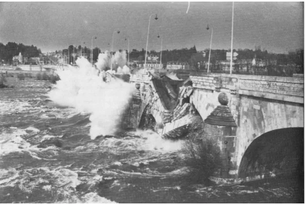
IGURESFigure 1.1 Progressive collapse of masonry arch bridge over the River Loire (Heyman, 1982) ... 2
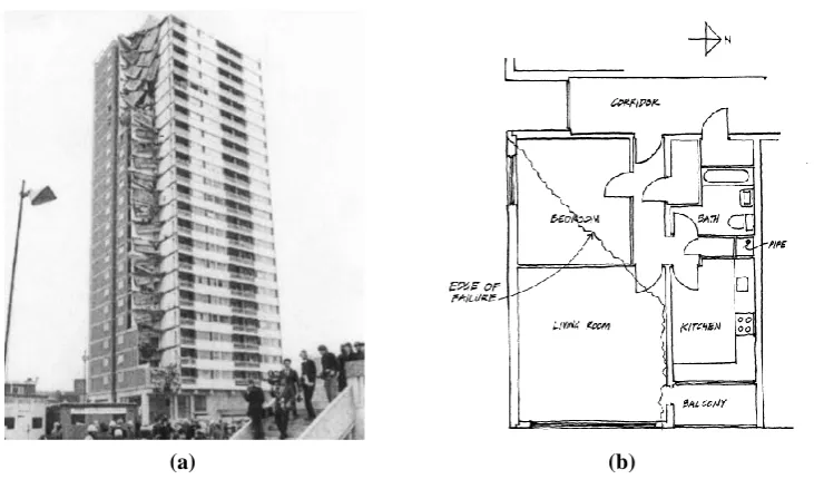
Figure 2.1 (a) Ronan Point apartment tower after collapse and (b) layout of apartment 90 (including the edge of failure) ... viii
Figure 2.2 Horizontal joint between floor slab and flank wall (Pearson and Delatte, 2005) ... ix
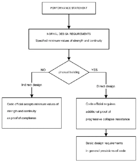
Figure 2.3 Timeline illustrating the development of provisions for robustness in UK codes of practice. ix Figure 2.4 Suggested progressive collapse design approach (McGuire, 1974)... xiii
Figure 2.5 Procedure for reducing the risk of progressive collapse (Leyendecker and Ellingwood, 1977) ... xv
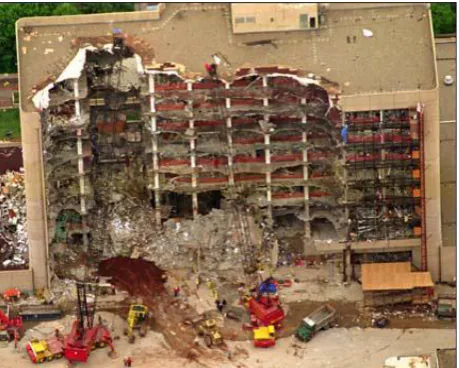
Figure 2.6 (a) Plan and (b) north elevation of the Murrah Building, showing the transfer girder, discontinuous columns and recessed edge beams (Osteraas, 2006) ... xvi
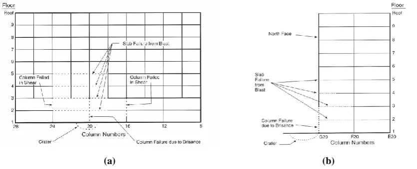
Figure 2.7 Schematic of the blast response of the Murrah Building (a) north elevation and (b) cross-section at Column Line 20 (FEMA, 1996) ... xvi
Figure 2.8 Damage to the Murrah Building, as a result of the blast and the subsequent progressive collapse ... xvii
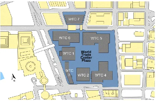
Figure 2.9 Plan of the World Trade Centre complex (FEMA, 2002) ... xviii
Figure 2.10 Structural details of World Trade Centre twin towers: (a) floor plan showing central core and floor trusses, (b) the exterior load-bearing frame of the towers and (c) plan and cross-section of the ‘hat truss’ atop each tower (FEMA, 2002) ... xix
Figure 2.11 World Trade Centre 1 (a) Aircraft impact zone and (b) damage to perimeter columns on the north face of the tower (FEMA, 2002) ... xx
Figure 2.12 Floor plan for World Trade Centre 1 indicating the extent of direct impact damage to floors 93 to 98 (NIST, 2005) ... xx
Figure 2.13 World Trade Centre 2 (a) Aircraft impact zone and (b) damage to perimeter columns on the south face (FEMA, 2002) ... xxii
Figure 2.14 Floor plan for World Trade Centre 2 indicating the extent of direct impact damage to floors 78 to 83 (NIST, 2005) ... xxii
Figure 2.15 The rubble pile which remained following the collapse of WTC 1 and 2 ... xxiv
Figure 2.16 Horizontal ties bridge across localised failure, while vertical ties redistribute the loads among the remaining floors ... xxvi
Figure 2.17 Partial collapse of Charles de Gaulle Airport Terminal 2E ... xxvii
Figure 2.18 Geometric nonlinearities in a frame following notional column removal ... xxx
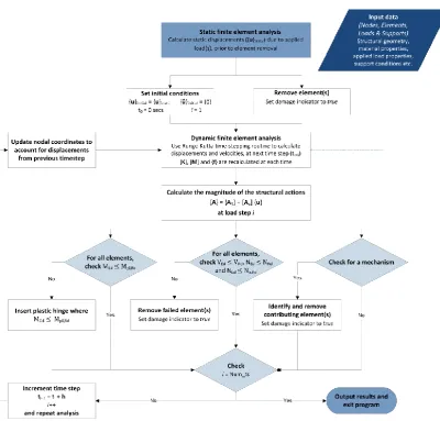
Figure 2.19 (a) External and (b) internal column removal locations (DoD, 2009) ... xliv Figure 2.20 Sudden column removal modelled using amplified static loading (Izzuddin et al., 2008)... l Figure 3.1 Overview of progressive collapse analysis algorithm ... 55
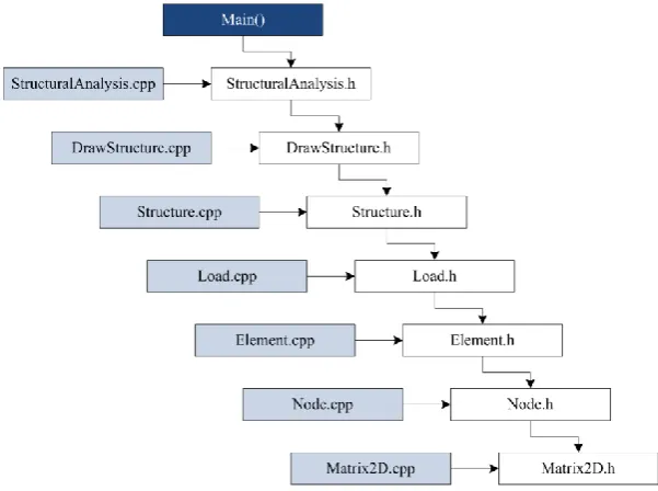
Figure 3.2 Class structure implemented in PCA2011 ... 56
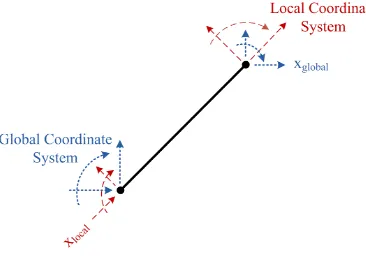
Figure 3.3 Positive sign convention for local and global axes ... 57
Figure 3.5 Axes used for section properties, following the naming convention used in EN 1993-1-1
(CEN, 2005) ... 58
Figure 3.6 Illustration of local and global coordinate systems ... 59
Figure 3.7 Flowchart describing static finite element analysis algorithm (FE_static) ... 60
Figure 3.8 Typical support types (a) fully fixed joint (encastré) (b) pinned joint (c) horizontal roller joint and (d) vertical roller joint ... 62
Figure 3.9 Basic difference between (a) static loading and (b) dynamic loading ... 63
Figure 3.10 Flowchart describing dynamic finite element analysis algorithm (FE_dynamic) ... 65
Figure 3.11 Flowchart describing PCA_linear_static ... 67
Figure 3.12 Flowchart describing PCA_nonlinear_static ... 71
Figure 3.13 (a) P-delta effect and (b) catenary action ... 72
Figure 3.14 (a) Typical stress-strain relationship for steel (not to scale) and (b) Ideal stress-strain relationship implemented in plastic analysis (elastic-perfectly plastic behaviour) ... 73
Figure 3.15 Plastification of a cross-section (a) simply-supported beam with load applied at mid-span, where the shaded area indicates the shape of the plastic zone, (b) moment-curvature relationship for simply supported beam and (c) stress distributions at the centre of the beam ... 74
Figure 3.16 Approach used when inserting plastic hinges ... 75
Figure 3.17 Algorithm implemented to check for and insert a plastic hinge ... 76
Figure 3.18 Bending of steel beams (a) with and (b) without local buckling (Wong, 2009) ... 77
Figure 3.19 Examples of plastic hinge configurations causing a local mechanism (highlighted in red) . 78 Figure 3.20 Algorithm implemented to check for and remove a mechanism ... 79
Figure 3.21 Flowchart describing PCA_nonlinear_dynamic ... 81
Figure 3.22 Relationship between damping ratio and frequency for mass proportional, stiffness proportional and Rayleigh damping ... 82
Figure 3.23 Flowchart describing the fourth order Runge-Kutta method ... 84
Figure 3.24 (a) Input data for example frame and (b) example frame... 85
Figure 3.25 Properties required to define (a) a point load, (b) an applied moment and (c) a universally distributed load ... 86
Figure 3.26 The CSV files containing the computed response can be opened in Microsoft Excel and manipulated as desired ... 86
Figure 3.27 Graphical output for PCA2011 showing the displaced shape, bending moment diagram, shear force diagram and axial force diagram for a frame following notional element removal ... 87
Figure 3.28 Graphical User Interface for PCA2011 ... 88
Figure 4.1 (a) Two storey, six bay frame selected for analysis and (b) reference numbers used when discussing the response of individual nodes and elements ... 91
Figure 4.2 Element removal locations considered ... 94
Figure 4.3 Static response when accidental load combination is applied to the undamaged frame (for section sizes selected for central column removal) ... 95
Figure 4.5 Linear static response following central column removal (members which have exceeded
their capacity are shown as red dashed lines) ... 96
Figure 4.6 Nonlinear static response following central column removal ... 97
Figure 4.7 Vertical displacement of Node 11 ... 99
Figure 4.8 Rotation of Node 8 ... 99
Figure 4.9 Rotation of Node 9 ... 99
Figure 4.10 Bending moment in Element 5 ... 100
Figure 4.11 Bending moment in Element 17 ... 100
Figure 4.12 Axial force in Element 5 ... 101
Figure 4.13 Axial force in Element 17 ... 101
Figure 4.14 Shear force in Element 6 ... 101
Figure 4.15 Shear force in Element 17 ... 101
Figure 4.16 Formation of plastic hinges following central column removal (nonlinear dynamic analysis) ... 102
Figure 4.17 Vertical displacement of Node 11 ... 104
Figure 4.18 Horizontal displacement of Node 8 ... 104
Figure 4.19 Rotation of Node 8 ... 104
Figure 4.20 Vertical Displacement of Node 8 ... 104
Figure 4.21 Bending moment in Element 17 ... 105
Figure 4.22 Bending moment in Element 23 ... 105
Figure 4.23 Bending moment in Element 6 ... 105
Figure 4.24 Bending moment in Element 5 ... 105
Figure 4.25 Axial force in Element 5 ... 106
Figure 4.26 Axial force in Element 17 ... 106
Figure 4.27 Shear force in Element 5 ... 107
Figure 4.28 Shear force in Element 6 ... 107
Figure 4.29 Shear force in Element 17 ... 107
Figure 4.30 Rotation of beam-column joint at Node 8 ... 108
Figure 4.31 Static response for accidental load case (with section sizes selected for peripheral column removal) ... 109
Figure 4.32 Peripheral column is replaced by a set of equivalent forces and moments ... 110
Figure 4.33 Linear static response following peripheral column removal (members which have exceeded their capacity are shown as red dashed lines) ... 110
Figure 4.34 Nonlinear static response following peripheral column removal ... 111
Figure 4.35 Vertical displacement of Node 2 ... 112
Figure 4.36 Horizontal displacement of Node 5 ... 112
Figure 4.37 Rotation of Node 5 ... 112
Figure 4.38 Rotation of Node 6 ... 112
Figure 4.39 Bending moment in Element 3 ... 113
Figure 4.41 Axial force in Element 4 ... 113
Figure 4.42 Axial force in Element 21 ... 113
Figure 4.43 Shear force in element 2 ... 114
Figure 4.44 Shear force in element 15 ... 114
Figure 4.45 Formation of plastic hinges following peripheral column removal (nonlinear dynamic analysis)... 116
Figure 4.46 Vertical displacement of Node 2 ... 117
Figure 4.47 Rotation of Node 2 ... 117
Figure 4.48 Horizontal displacement of Node 2 ... 117
Figure 4.49 Vertical displacement of Node 5 ... 118
Figure 4.50 Rotation of Node 5 ... 118
Figure 4.51 Bending moment in Element 15 ... 119
Figure 4.52 Bending moment in Element 21 ... 119
Figure 4.53 Bending moment in Element 2 ... 119
Figure 4.54 Bending moment in Element 4 ... 119
Figure 4.55 Bending moment in Element 3 ... 119
Figure 4.56 Axial force in Element 3 ... 120
Figure 4.57 Axial force in Element 21 ... 120
Figure 4.58 Shear force in Element 2 ... 121
Figure 4.59 Shear force in Element 3 ... 121
Figure 4.60 Shear force in Element 15 ... 121
Figure 4.61 Rotation of joint at Node 5 ... 122
Figure 4.62 Vertical displacement of Node 11 ... 123
Figure 4.63 Rotation of joint at Node 8 ... 123
Figure 4.64 Horizontal displacement of Node 8 ... 124
Figure 4.65 Vertical displacement of Node 8 ... 124
Figure 4.66 Rotation of Node 8 ... 124
Figure 4.67 Frequency response for horizontal displacement of Node 8 ... 124
Figure 4.68 Frequency response for vertical displacement of Node 8 ... 124
Figure 4.69 Frequency response for rotation of Node 8 ... 124
Figure 4.70 Bending moment in Element 17 ... 125
Figure 4.71 Axial force in Element 17 ... 125
Figure 4.72 Vertical displacement of Node 2 ... 125
Figure 4.73 Rotation of joint at Node 5 ... 125
Figure 4.74 Horizontal displacement of Node 5 ... 126
Figure 4.75 Vertical displacement of Node 5 ... 126
Figure 4.76 Rotation of Node 5 ... 126
Figure 4.77 Frequency response for horizontal displacement of Node 5 ... 126
Figure 4.78 Frequency response for vertical displacement of Node 5 ... 127
Figure 4.80 Bending moment in Element 21 ... 127
Figure 4.81 Axial force in Element 21 ... 127
Figure 5.1 (a) Frame selected for analysis and (b) element removal locations ... 132
Figure 5.2 Location of plastic hinges following the removal of the central ground floor column, numbered in order of occurrence (where the first number represents the formation of the plastic hinge and the number in brackets represents its subsequent closing) ... 137
Figure 5.3 Peak vertical displacement ... 138
Figure 5.4 Peak horizontal displacement ... 138
Figure 5.5 Peak nodal rotation ... 138
Figure 5.6 Peak rotation of beam-column joints ... 138
Figure 5.7 Peak axial force in beams ... 140
Figure 5.8 Peak axial force in columns ... 140
Figure 5.9 Peak shear force in beams ... 140
Figure 5.10 Peak shear force in columns ... 140
Figure 5.11 Location of plastic hinges following the removal of the peripheral ground floor column, numbered in order of occurrence (where the first number represents the formation of the plastic hinge and the number in brackets represents its subsequent closing) ... 141
Figure 5.12 Peak vertical displacement ... 143
Figure 5.13 Peak horizontal displacement ... 143
Figure 5.14 Peak nodal rotation ... 143
Figure 5.15 Peak rotation of beam-column joints ... 143
Figure 5.16 Peak axial force in beams ... 144
Figure 5.17 Peak axial force in columns ... 144
Figure 5.18 Peak shear force in beams ... 144
Figure 5.19 Peak shear force in columns ... 144
Figure 6.1 Definition of direct and indirect consequences for a risk-based robustness assessment ... 150
Figure 6.2 Various scales at which a system can be defined for robustness assessment ... 150
Figure 6.3 Activity patterns of working age, professional females during a normal work day (Coburn and Cohen, 2004) ... 152
Figure 6.4 Murrah Building after the bombing ... 158
Figure 6.5 Scatterplot of opportunity costs per statistical life saved, based on the amount spent on US government programmes between 1967 and 2001 (based on Morrall, 2003) ... 159
Figure 6.6 Relationship between the number of fatalities and the number of injuries for past building failures with 95% confidence interval ... 163
Figure 6.7 Distribution of injuries in the Murrah Building by patient status (Mallonee et al., 1996) ... 164
Figure 6.8 New York Skyline on September 11, 2001 ... 170
Figure A.1 Relationship between hazard, vulnerability, damage tolerance and robustness ...A2
Figure B.1 Uniform beam element with 6 degrees of freedom ... B1
Figure B.2(a) Direction of positive forces and displacements and (b) axes for section properties in
Figure B.3(a) Member under compression (b) shear forces in a member and (c) sagging of a member . B2
Figure B.4 Longitudinal motion of beam element ... B3
Figure B.5 Uniform Beam Element ... B4
Figure B.6 Fixed-pinned beam element with uniformly distributed load of length c applied a distance a
– c/2 from the start node ... B10
Figure B.7 Beam element with uniformly distributed load of length c applied a distance a – c/2 from the
start node ... B12
Figure B.8 Beam element with moment applied a distance a from the start node ... B15
Figure B.9 Beam element with point load applied a distance a from the start node ... B17
Figure B.10 Illustration of local and global coordinate systems ... B19
L
IST OFT
ABLESTable 2.1 Definition of risk categories using the risk factor for a building and the recommended design
criteria associated with each category (DTLR, 1999a; DTLR, 2001) ... xxxiv
Table 2.2 Definition of consequence classes, Approved Document A (ODPM, 2004) ... xxxiv
Table 2.3 Definition of consequence classes, Annex B to EN 1990 (CEN, 2002a) ... xxxvi
Table 2.4 Definition of consequence classes, EN 1991-1-7 (CEN, 2006) ... xxxvi
Table 2.5 Definition of occupancy categories in DoD progressive collapse design guideline (DoD, 2003; DoD, 2005b; DoD, 2009)... xlii Table 2.6 Dynamic load increase factors (ΩL) for static analysis (DoD, 2009) ... xlv Table 4.1 Non-structural permanent actions applied to the selected frame (Arup, 2008)... 92
Table 4.2 Properties for the minimum section sizes to resist the persistent load case ... 93
Table 4.3 Properties of section sizes selected for central column removal (accidental design case) ... 95
Table 4.4 Properties of section sizes selected for peripheral column removal (accidental design case) 109 Table 5.1 Parameters varied and the set of values considered ... 133
Table 5.2 Non-structural permanent actions applied to the selected frame (Arup, 2008)... 133
Table 5.3 Section sizes employed, and their properties, for the various bay widths considered (central column removal) ... 136
Table 5.4 Length of time the plastic hinges at the suddenly unsupported node undergo increasing plastic rotations ... 136
Table 5.5 Minimum capacities of peripheral and internal ties, EN 1991-1-7 (CEN, 2006) ... 139
Table 5.6 Section sizes employed, and their properties, for the various bay widths considered (peripheral column removal)... 141
Table 5.7 Length of time the plastic hinges at the suddenly unsupported node undergo increasing plastic rotations ... 142
Table 5.8 Minimum capacities of peripheral and internal ties, EN 1991-1-7 (CEN, 2006) ... 144
Table 6.1 Proposed classification of consequences ... 153
Table 6.2 EMS damage grades with proposed classification based on the percentage of the horizontal area which has collapsed (adapted from Coburn, Spence et al., 1992) ... 154
Table 6.3 Proposed values for M2 based on typical average daily occupancy levels for buildings (Coburn et al., 1992) ... 156
Table 6.4 Proposed values for M4 and M5, based on values derived for building failure following earthquake (Coburn and Spence, 2002) ... 157
Table 6.5 Estimates of the value of a statistical life (VSL) used in government decision making ... 161
Table 6.6 Estimates of the value of a statistical life (VSL) from the literature ... 162
Table 6.7 Number of fatal and nonfatal injuries in the Murrah Building (Mallonee et al., 1996) ... 163
Table 6.8 Abbreviated Injury Scale (reproduced from GRA Incorported, 2007) ... 165
Table 6.10 Structural and non-structural costs (based on HAZUS (FEMA, 2003)) for full replacement of
buildings with high consequences of failure ... 167
Table 6.11 Mean values of the overall loss (as a percentage of the full replacement cost) for various
levels of damage... 168
Table 6.12 CO2 emissions per tonne for typical building materials (Amos, 2010; Janssens et al., 2011)
... 171
Table 6.13 Average values of CO2 emissions per km for different vehicle types (AEA, 2011) ... 172
Table C.1 Nominal values for the yield strength ( ) and ultimate tensile strength ( ), for hot-rolled
structural steel, extracted from Table 3.1 of EN 1993-1-1 (CEN, 2005) ... C2
Table C.2 Local buckling limits for I-sections, extracted from Table 5.2 of EN 1993-1-1 (CEN, 2005)
... C3
Table C.3 Selection of buckling curve for a rolled I-section, for buckling about y-y axis (Table 6.2, EN
1993-1-1) ... C8
Table C.4 Imperfection factors for buckling curves (Table 6.1, EN 1993-1-1) ... C8
Table D.1 Hot-rolled Universal Beam sections (BSI, 2005) ...D4
Table D.2 Hot-rolled Universal Column sections (BSI, 2005) ...D6
Table E.1 Opportunity costs per statistical life saved based on the amount spent on US Government
programmes from 1967 to 2001 (Morrall, 2003) ... E3
Table E.2 Estimates of the value of a statistical life (VSL) from the literature ... E4
L
IST OFN
OTATIONThe following is a list of the principal notation used in this thesis. All of the following are defined in the text where they first appear and are listed here for clarity.
L
ATIN UPPERCASE LETTERSCross-sectional area
Shear area
The percentage of the occupiable area that has collapsed at the ith storey
( ) In a probabilistic expression of risk, the consequences corresponding to the
structural performance state
( ) In a probabilistic expression of risk, the direct consequences corresponding to the
initial damage state
( ) In a probabilistic expression of risk, the indirect consequences corresponding to the
structural performance state
In a probabilistic expression of risk, the initial damage state arising as a result of
the hazards
Young’s modulus of elasticity
Characteristic value of permanent action j
In a probabilistic expression of risk, the hazard (which may be an accidental
action, impact, human error etc.)
Second moment of area
The number of fatalities (as a result of a building collapse)
The number of injured individuals (as a result of a building collapse)
The maximum number of people in a building (at any time)
Length
Design moment resistance
Design value of the bending moment
Design elastic moment resistance
Design moment resistance, reduced due to the shear force
Design plastic moment resistance
Design moment resistance, reduced due to the shear force
Design moment resistance, reduced due to the shear and axial forces
The percentage of people in a building at collapse (fatalities equation)
The portion of a building’s occupants which will be trapped by the collapse, for the
failure scenario under consideration (fatalities equation)
The number of trapped individuals killed instantly by the collapse, for the failure
scenario under consideration (fatalities equation)
The number of trapped individuals who died post-collapse as a result of their
injuries, for the failure scenario under consideration (fatalities equation)
Design compression resistance
The number of potential damage states resulting from the hazards
Design value of the axial force
The number of hazards a structure is subjected to (corresponding to single or
multiple events)
The number of structural performance states arising as a result of the damages
The number of storeys in a building
Total number of time steps to be executed (dynamic analysis)
Design tension resistance
Characteristic value of the leading variable action
Characteristic value of variable action i
Risk for a structure
In a probabilistic expression of risk, the overall structural performance state
Design shear resistance
Design value of the shear force
L
ATIN LOWERCASE LETTERSIn-plane column spacing
Out-of-plane column spacing
yield stress
Size of time step (dynamic analysis)
Integers used for analysis loops (in PCA2011)
The storey in which the hazard occurs
Self-weight of the structural members
Time at the ith time step (dynamic analysis)
Initial time (time at which dynamic analysis begins)
G
REEK SYMBOLSRayleigh damping coefficients
The percentage of people able to evacuate the building before collapse, in the storeys
below that in which the hazard occurs
The percentage of people able to evacuate the building before collapse, in the storeys
above and including that in which the hazard occurs
Partial factor for permanent action j (EN 1990)
Partial factor for material property i (EN 1990)
Partial factor for the leading variable action (EN 1990)
Partial factor for variable action i (EN 1990)
Yield strain
Strain-hardening strain
Modal damping factor, for the rth mode of vibration Density
Ultimate yield stress
Factor for the combination of action effects (EN 1990)
Factor for the combination value of a variable action (EN 1990)
Factor for the frequent value of a variable action (EN 1990)
Factor for the quasi-permanent value of a variable action (EN 1990)
Magnitude of universally distributed load
Natural frequency, for the rth mode of vibration
M
ATRICESMatrix
Matrix of shape functions for element i
Damping matrix for the structure
Stiffness matrix for the structure
Stiffness matrix for element i, in global coordinates
Stiffness matrix for element i, in local coordinates
Mass matrix for the structure
Mass matrix for element i, in global coordinates
Mass matrix for element i, in global coordinates
Transformation matrix for element i
V
ECTORSVector
Magnitude of the structural action, at each internal coordinate, along element i
Vector of load functions for element i
Restraining force vector for the structure
Restraining force vector for element i, in global coordinates
{ } Restraining force vector for element i, in local coordinates
Vector of displacements, at the degrees of freedom
̇ Vector of velocities, at the degrees of freedom
̈ Vector of accelerations, at the degrees of freedom
{ } Vector of displacements for element i, in global coordinates
P
ROBABILITIES( ) In a probabilistic risk assessment, the probability of occurrence of the hazard
( ) In a probabilistic risk assessment, the conditional probability of the
damage state
given the hazard
( ) In a probabilistic risk assessment, the conditional probability of the
adverse state
L
IST OFA
BBREVIATIONSThe following is a list of the abbreviations used in the text. Each of the following are defined where they first appear in the text and are listed here for reference.
AIS Abbreviated Injury Severity
AAAM Association for the Advancement of Automotive Medicine (US)
ANSI American National Standards Institute
ASCE American Society of Civil Engineers
ASHRAE American Society of Heating Refrigeration and Air-conditioning
Engineers
BOCA Building Officials and Code Administrators (US)
BRE Building Research Establishment, UK (www.bre.co.uk)
BSI British Standards Institution (UK)
CEN European Committee for Standardization (Comité Européen de
Normalisation)
COST European Cooperation in Science and Technology (www.cost.eu)
CSV Comma Separated Value (file type)
DAF Dynamic Amplification Factor
DCLG Department for Communities and Local Government (UK)
DECC Department for Energy and Climate Change (UK)
Defra Department for Environment, Food and Rural Affairs (UK)
DfT Department for Transport (UK)
DoD Department of Defence (US)
DoEHLG Department of the Environment, Heritage and Local Government
(Ireland)
DTLR Department for Transport Local Government and the Regions (UK)
EMS European Macroseismic Scale
EPA Environmental Protection Agency (US)
FE Finite Element
FE_static Static finite element analysis routine (developed by the author)
FE_dynamic Dynamic finite element analysis routine (developed by the author)
FEM Finite Element Method
FEMA Federal Emergency Management Agency (US)
GSA General Services Administration (US)
GUI Graphical User Interface
GCP Gross City Profit
GDP Gross Domestic Profit
HSE Health and Safety Executive (UK)
IABSE International Association for Bridge and Structural Engineering
(www.iabse.org)
ICBO International Conference of Building Officials (US)
JCSS Joint Committee on Structural Safety (www.jcss.ethz.ch)
LQI Life Quality Index
MHLG Ministry of Housing and Local Government (UK)
NIST National Institute of Science and Technology (US)
NRCC National Research Council of Canada
NSAI National Standards Authority of Ireland
ODPM Office of the Deputy Prime Minister (UK)
PCA2011 Progressive collapse analysis program (developed by the author)
PCA_linear_static Linear static progressive collapse analysis routine (developed by the
author)
PCA_nonlinear_static Nonlinear static progressive collapse analysis routine (developed by
the author)
PCA_nonlinear_dynamic Nonlinear dynamic progressive collapse analysis routine (developed
by the author)
PIAB Personal Injuries Assessment Board (Ireland)
SBCCI Southern Building Code Congress International (US)
SDL Simple DirectMedia Layer (www.libsdl.org)
VSL Value of a statistical life
WHO World Health Organisation
WTP Willingness to pay
Chapter 1 I
NTRODUCTION
1.1
W
HAT IS PROGRESSIVE COLLAPSE?
Progressive collapse is characterised by the sequential spread of an initial local failure, resulting in
a cascade of failures which affects a larger portion of the structure. A collapse of this nature is mostly of concern to structural engineers if there is a pronounced disproportion between the initiating event and the resulting collapse, in other words if it is a disproportionate collapse. It is this disproportionality that results in differences between the various definitions of progressive collapse in the literature. In general, these can be considered in two categories: those that consider disproportionality to be a distinguishing feature of progressive collapse (e.g. GSA, 2003; ASCE, 2005) and those that consider progressive collapse and disproportionate collapse separately (e.g. IStructE, 2010). However, progressive collapse is generally of concern to structural engineers only if the resulting level of damage is disproportionate. Therefore, it is considered appropriate that disproportionality is a characteristic of progressive collapse (unless explicitly stated otherwise). In view of this, the following definition is adopted in this thesis.
Progressive collapse is the sequential spread of an
initial local failure, from component to component,
eventually resulting in either the collapse of an entire
structure or a disproportionately large part of it.
use, malicious action, exposure to aggressive agents and so on. As a result of the unforeseen nature of these events, it is impossible to develop a quantitative description of the magnitude, duration and location of the loading. This presents the designer with a significant challenge when trying to improve structural safety. Finally, as structural engineers cannot reasonably design for every hazard that a building may be subjected to during its lifetime, a general design approach is required to account for the risks associated with low-probability high-consequence events.
1.2
B
ACKGROUND [image:25.595.171.468.378.578.2]Progressive collapse is not a new problem for structural engineers, who have always been in some way concerned with the possibility that the loss of load-carrying capacity of a relatively small portion of a structure could lead to a disproportionate level of damage. For example, during the 18th century the piers of arch bridges became more slender and consequently the possibility of progressive collapse increased. During construction these bridges had to have all spans supported by centring that was later removed simultaneously. If a single span in such a bridge fails, this would initiate an inevitable progressive collapse (see Figure 1.1).
Figure 1.1 Progressive collapse of masonry arch bridge over the River Loire (Heyman, 1982)
has highlighted the need to consider hazards (explosions or detonations) that may not have been viewed as significant in the past.
The partial collapse of the Ronan Point apartment tower in 1968 was a pivotal event with regard to progressive collapse. This event spurred a significant amount of research into the topic and prompted the Fifth Amendment to the UK Building Regulations (ODPM, 1970). As a result, the possibility of structural collapse was considered for the first time in a regulatory document. From this point on, buildings were required to exhibit a minimum level of robustness to resist progressive collapse. Outside the UK, the Ronan Point collapse also triggered changes to codes of practice, and in countries such as the US and Canada general provisions for structural integrity and the prevention of progressive collapse were introduced into design codes (ANSI, 1972; BOCA, 1972; NRCC, 1975; SBCC, 1994; ICBO, 1997).
More recently, the bombing of the Alfred P Murrah Federal Building (1995) and the high-profile terrorist attacks on the World Trade Centre (2001) have highlighted the potential risk of malicious attacks designed to cause structural collapse. As a result, the topics of progressive collapse and robustness of structures are receiving renewed attention (GSA, 2003; DoD, 2005a; DoD, 2009; IStructE, 2010; Faber and Narasimhan, 2011; ASCE, DRAFT).
Finally, as a result of the recent introduction of the Eurocodes and the pending revision of the National Building Regulations, regulatory requirements for progressive collapse in the Republic of Ireland are currently undergoing significant changes. Consequently, structural engineers are required to consider the possibility of progressive collapse in greater detail than was previously the case. Meanwhile, for structures with high perceived consequences of failure, a systematic risk assessment must be undertaken, accounting for all undesired (foreseeable and unforeseeable) events and their perceived consequences.
1.3
R
ESEARCH OBJECTIVESFollowing a substantial review of the literature on structural robustness and progressive collapse (outlined in Chapter 2), a number of research objectives have been identified. These can be summarised as follows:
To develop a structural analysis program that is capable of modelling the complex
structural behaviour associated with progressive collapse. Specifically, this program will
To demonstrate the application of this analysis program and investigate the behaviour of
steel moment-resisting frames following localised failure. In view of this, an example structure will be selected and the response of this structure will be compared for two different initiating events: (i) the sudden removal of the central ground floor column and (ii) the sudden removal of the peripheral ground floor column. The objective of this study is to gain a better understanding of the post-damage behaviour of steel structures and of the differences in the structural behaviour observed, for the two initiating events considered.
To study the importance of dynamic effects when considering progressive collapse. This
will be achieved by computing the response of the example structure for three alternative types of analysis, of increasing complexity: linear static analysis; nonlinear static analysis; and nonlinear dynamic analysis. The results of these simulations then will be compared, focusing on the advantages and disadvantages of the different types of analysis. Specifically, any overestimations or underestimations in the peak response of the individual members will be identified. Furthermore, an investigation into the influence of damping on the nonlinear dynamic response will be undertaken, with the goal of providing further insight into the level of damping which should be modelled when analysing the response of a structure to localised failure.
To perform a parametric study to investigate the factors influencing the structural
response following localised damage. Specifically, the effect of variations in the geometric
properties of the structure on the computed response will be investigated. The peak displacements, internal forces and bending moments observed will be compared and any relationship between the varied parameters will be identified.
To develop a framework for quantifying the consequences of building failure, as a result
of an unidentified hazard. This will primarily focus on developing procedures to quantify the
various consequences which may be observed following building failure: from structural damage to injuries and fatalities, functional downtime, environmental damage and economic impacts. The aim of this chapter is to develop guidance to assist engineers in quantifying the ‘cost-of-failure’. This forms the final step in a risk-based assessment of robustness and, together with the analysis tool developed, can be used to estimate the risk for the structure under consideration.
1.4
O
UTLINE OF THESISThe objectives listed in Section 1.3 are addressed in the following six chapters. A brief outline for each of these chapters is provided below.
collapse and outlines the historical development of regulatory requirements for progressive collapse in the UK. Following this, a series of case studies of well-known building collapses is presented. The various collapse mechanisms observed are described and the implications for collapse resistant design are discussed. The general design strategies for reducing the vulnerability of a structure to progressive collapse are then outlined. Furthermore, a summary of the implementation of these design strategies in current building codes and design guidelines is presented. Finally, this chapter concludes with an overview of recent scientific contributions in this subject area and discusses the rationale behind the research objectives chosen for consideration in this thesis.
Chapter 3 describes the progressive collapse analysis program PCA2011 developed as part of this research. In order to identify whether a structure is unduly sensitive to localised damage, this program considers the notional removal of one or more primary load-bearing members from the numerical model. PCA2011 is based on the finite element method and models the complex structural behaviour associated with progressive collapse using linear static, nonlinear static and nonlinear dynamic analysis. The members of the structure are represented using Euler-Bernoulli beam elements and all of the joints are assumed to be fully fixed. The effects of material nonlinearities are modelled using lumped plastic hinges and geometric nonlinearities are accounted for by regularly updating the structural matrices to include the displaced shape of the structure. In order to compute the time-varying response of the structure following the loss of a member, a fourth order Runge-Kutta routine is implemented to numerically integrate the dynamic equilibrium equations and compute the unknown displacements and velocities. Meanwhile, viscous damping effects are incorporated in the dynamic analysis algorithm using Rayleigh damping theory. This chapter describes these features in detail, using flowcharts to illustrate the main algorithms implemented in the program.
In Chapter 4, PCA2011 is applied to study the response of a two storey, six bay steel moment-resisting frame, following the sudden removal of (i) the central ground floor column and (ii) the peripheral ground floor column. A comparison of the computed displacements and internal forces (determined using linear static, nonlinear static and nonlinear dynamic analysis) is presented, and the advantages and disadvantages of the different types of analysis are highlighted. Specifically, this chapter investigates the influence of dynamic effects on the post-damage behaviour of steel structures. Finally, the results of an investigation into the influence of damping on the nonlinear dynamic response are outlined.
post-damage behaviour of steel framed structures and describes the magnitude of the displacements and internal forces which may be anticipated during a progressive collapse. Additionally, the relationship between the observed response and the geometry of the structure is explored.
In Chapter 6 a framework is developed for assessing the consequences of building failure, due to an unidentified hazard. This chapter adopts a multi-disciplinary approach and presents a detailed overview of consequence assessment, drawing from a wide range of subject areas and focusing on their relevance to building failures as a result of an unidentified hazard. The multi-dimensional and variable aspects of the ‘cost-of-failure’ are discussed and a categorisation of failure consequences, as well as associated models for their quantification, is developed. The information outlined in this chapter is intended to assist designers when undertaking a risk analysis to assess the sensitivity of a building to progressive collapse. This chapter has been intentionally placed at the end of the main body of this thesis as consequence assessment is often the final step in a risk-based robustness evaluation. Specifically, PCA2011 could first be employed to determine the extent of damage which may occur following localised failure due to some unidentified hazard. Following this, the framework outlined in this chapter can be applied, together with the predicted damage, to quantify the risk for the structure under consideration.
Chapter 2 L
ITERATURE REVIEW
2.1
I
NTRODUCTIONThis chapter presents a comprehensive review of the current literature on progressive collapse and robustness of structures. Firstly, an overview of the Ronan Point collapse will be provided, and the subsequent development of regulatory requirements for progressive collapse in the UK will be outlined. Following this, a series of well-known building collapses will be discussed, focusing on the collapse mechanisms observed and the implications for collapse resistant design. The general design strategies for reducing the vulnerability of a structure to progressive collapse are then outlined. Furthermore, the implementation of these design strategies in current building codes and design guidelines will be summarised. Finally, this chapter concludes with an overview of recent scientific contributions in this subject area.
2.2
T
HE COLLAPSE OFR
ONANP
OINT APARTMENT TOWER(1968)
The 22-storey Ronan Point apartment tower was constructed between July 1966 and March 1968 (Pearson and Delatte, 2005). This was the second of nine identical residential towers to be completed in Newham, East London, in an attempt to tackle a housing shortage at that time. The apartments were constructed using the Larson Nielson system: an industrialised method of building which originated in Denmark in 1948. This construction technique was selected due to the high degree of prefabrication possible, which was expected to improve quality, to increase the rate of construction and to reduce the amount of skilled labour required. Each apartment tower was 64 m (210 ft) high, with overall plan dimensions of 24.4 m (80 ft) by 18.3 m (60 ft). All of the structural elements consisted of precast concrete panels, with each floor directly supported by the storey below. Once the wall and floor panels were slotted together, the joints were bolted and filled with dry-pack mortar to increase their strength.
bedroom, of the 18th floor apartment. This left the floor slab above unsupported. Floors 19 to 22 were unable to cantilever across the initial damage below, and subsequently fell onto the 18th floor. The impact loading on the 18th floor resulted in its failure, and the collapse sequence continued to the ground. 17 people were injured and 4 killed by the collapse.
A panel was quickly formed by the government to investigate the collapse and the panel’s report was issued five months later (Griffiths et al., 1968). The panel’s investigations revealed the pressure of the explosion was within the ‘normal’ range for gas explosions, with the pressure on the flank wall momentarily peaking at 34-42 kPa (5-6 lb/in2). The panel also determined that the maximum internal pressure the external wall panel could withstand was a mere 19.3kPa (2.78 lb/in2). However had only the external walls been lost in the blast, the level of damage may have been considered proportionate to the cause. It was the ensuing progressive collapse which resulted in a disproportionate level of damage. This was attributed to an inherent lack of robustness in the building design, and particularly to a lack of horizontal continuity between the floor slab and flank wall (see Figure 2.2). Due to continuing concerns over the structural integrity of the Ronan Point apartment tower, the structure was demolished in May 1986 (Bussell and Jones, 2010).
In general, the standards of workmanship observed at Ronan Point were found to be satisfactory and the panel’s report emphasised that no deficiency in workmanship was responsible for this collapse. However, when dismantling the tower, examples of poor workmanship were found throughout. In particular, the crucial horizontal joints between the floor slab and flank wall were found to be unsatisfactory (Pearson and Delatte, 2005; Schmidt, 2005). This further compromised the overall structural robustness of the building.
(a) (b)
Figure 2.1 (a) Ronan Point apartment tower after collapse and (b) layout of apartment 90
[image:31.595.138.504.58.273.2]Figure 2.2 Horizontal joint between floor slab and flank wall (Pearson and Delatte, 2005)
2.3
T
HEI
MPLICATIONS OF THER
ONANP
OINT COLLAPSEThe partial collapse of the Ronan Point apartment tower triggered a surge of interest in progressive collapse, with over 300 engineering articles and research reports published on the topic in the following decade (Longinow and Ellingwood, 1998). As a result of this event, a number of countries introduced regulatory provisions to minimise the risk of progressive collapse. This section outlines the development of these provisions, which to this day have remained relatively unchanged, and summarises the main research contributions during this period.
2.3.1
D
EVELOPMENT OF PROVISIONS FOR ROBUSTNESS IN CODES OF PRACTICEFigure 2.3 Timeline illustrating the development of provisions for robustness in UK codes of practice
Inquiry’s recommendation that all buildings over six storeys (constructed with load-bearing precast concrete panels) should be appraised by a structural engineer, who should consider:
(i) Their susceptibility to progressive collapse;
(ii) The buildings ability to resist the maximum wind loads which may occur; and (iii)Their behaviour in fire.
As an appendix, the circular provided technical advice outlining the measures to be applied in order to avoid progressive collapse. Two basic methods of preventing progressive collapse were provided: Method A and Method B.
Method A relied on the provision of ‘alternative paths of support to carry the load, assuming the removal of a critical section of the load-bearing walls’ (MHLG, 1968). A critical section was defined as the greater of the distance between substantial adjoining walls, the distance between a substantial adjoining wall and a return end, and the length of a precast wall panel. While, a ‘substantial wall’ was later defined (IStructE, 1968a) as having mass equivalent to 64 mm (2.5 in) thickness of solid concrete. With regard to this approach, minimum requirements for the provision of continuity in the horizontal plane were included, specifying that steel connections should be provided between:
Floor slabs and the supporting external load-bearing wall;
Adjacent floor slabs over internal load bearing walls; and
Adjacent external load-bearing walls.
It was also required that the structure above was capable of spanning across a removed element, by arching, beam or cantilever action. As a minimum, the floor and roof elements were required to have a tensile resistance of 44 kN/m (3000 lbf/ft). This figure is determined by calculating a static pressure of 34.5 kPa (5 lb/in2) applied over half of the storey height, taken as 2.5m (IStructE, 1968a). This is the first implementation of the tying force requirements (see Section 2.6.1) which are a common feature of progressive collapse provisions in modern guidelines and codes of practice.
Alternatively, Method B required that the structure possessed sufficient ‘stiffness and continuity so as to ensure the stability of the building against forces liable to damage the load supporting
Soon after the publication of Circular 62/68 the Institution of Structural Engineers published RP/68/01, setting out the general principles of structural stability and the prevention of progressive
collapse (1968b). This report was intended to expand upon the circular’s recommendations and was primarily concerned with large residential buildings constructed using prefabricated concrete panels, but could also be applied to other forms of construction. RP/68/01 advised that at the planning stage the building should be laid out in such a way that it is as stiff as possible. In particular, substantial cross walls should be incorporated to provide lateral restraint to the main load-bearing walls and to minimize the unsupported span following local failure. This report also suggested that there are two types of collapse which should be considered: the pack-of-cards type of collapse, triggered by instability in the structure, and the chain reaction type of collapse, in which one element falls on an element below leading to its failure. No further guidance was given in this document on methods for appraising existing buildings, or on possible revisions to the Building Regulations and Design Codes.
The following May, the Institution of Structural Engineers published RP/68/03: ‘Guidance on the Design of Domestic Accommodation in Loadbearing Brickwork and Blockwork to Avoid Collapse following an Internal Explosion’. This report elaborated on the recommendations of RP/68/01 for new buildings from 7-12 storeys and it was the Institution’s intention that this report would be of use to the drafting committees for the relevant codes and guidelines. The recommendations of RP/68/03 were based on a proposed ‘ideal situation’: where domestic buildings would be designed to resist a specified static pressure, and to bridge over structural damage from pressures exceeding this value. In this document, the specified static pressure was taken as 17 kPa (2.5 lb/in2). This value is half the static pressure of 34.5 kPa (5 lb/in2) recommended in Circular 62/68, but no explanation for the reduction was given.
Finally, in early 1970, the Fifth Amendment to the Building Regulations (ODPM, 1970) was introduced, coming into operation in England and Wales on April 1 that year. As a result, the possibility of structural collapse was considered for the first time in a regulatory document. Hereafter all buildings with five or more storeys were required to remain stable following the removal of any structural member under specified loading conditions. Any damage resulting from the removal of a structural element must be limited to the immediately-affected storey and the immediately-adjacent storeys (if any). Additionally, the damage must not exceed an area of 70 m2 (750 ft2), or 15% of the horizontal floor area, whichever is the lesser. This limit was derived from the Ronan Point collapse and is intended to limit the damage to one notional apartment (Harding and Carpenter, 2009). Alternatively if this requirement cannot be met, the member must be designed to resist a static pressure of 34 kN/m2 (5 psi) applied in any direction.
Specifically, RP/68/04 proposed that a fully framed (steel or concrete) structure, designed for continuity at the joints, would be able to ‘accommodate the unpredictable additional loads and effects’ under consideration, on condition that:
It was designed in accordance with the then current codes of practice for steel and concrete (CP 114:1957; BS 449:1959; CP 115:1959; CP 116:1965).
All structural elements (including floors) were provided with continuous horizontal ties of specified strength.
Whereas, for discontinuous structures or materials/structures not previously mentioned, this report endorsed the recommendations of Fifth Amendment. These comments were later formally published as report RP/68/05 (IStructE, 1971). This document reiterated the recommendations of RP/68/04 and expressed the Institution’s concern that the Fifth Amendment would lead to unnecessary structural strength and design costs.
Despite resistance from the engineering community, the requirements introduced in the Fifth Amendment were quickly incorporated into the then-current code of practice for precast concrete CP 116 (BSI, 1970). Additionally, requirements for peripheral, internal and vertical ties to be included throughout a structure (proposed in Circular 62/68 and in the reports by the Institution of Structural Engineers) were included. Subsequent revisions to UK codes of practice (BSI, 1972; BSI, 1978; BSI, 1985a; BSI, 1985b etc.) have continued to employ provisions for incorporating robustness and avoiding disproportionate collapse, following the same general format.
Outside the UK, the Ronan Point collapse also triggered changes to codes of practice. Specifically, general provisions for structural integrity and the prevention of progressive collapse were gradually introduced in the US and Canada. These changes are summarised in Section 2.7.
2.3.2
I
NITIAL RESEARCH ON PROGRESSIVE COLLAPSEAs well as triggering the introduction of regulatory requirements for the prevention of progressive collapse, Ronan Point spurred a significant amount of research into the topic. The papers published in the following years introduced many of the principles which form the basis of modern research in this field. This section gives an overview of a selection of the pertinent publications from this period.
Later, McGuire (1974) discussed the problem of progressive collapse and measures for its prevention. Specifically, this paper outlines the changes to UK codes of practice implemented in response to the Ronan Point collapse. In this overview, McGuire referred to the various provisions as the alternate path method, specific local resistance method and general structural integrity: corresponding to the design of a structure to remain stable following the removal of a structural member, the design of a member to resist a static pressure of 34 kN/m2 (5 psi) and the provision of ties to bind the structural elements together in a prescribed way, respectively. To the authors’ knowledge this is the first time these approaches have been referred to using these titles, which today are regularly used in US-based progressive collapse literature. This paper goes on to stress the need for codes and guidelines that specifically address progressive collapse; this is based on the authors predictions that the frequency of abnormal loading is likely to continue increasing in the future, while the margin of safety in framed structures will decrease as the reduced margin of safety in steel and concrete specifications is fully exploited. In view of this, McGuire proposed that progressive collapse codes or specifications should:
Provide adequate guidance to the ways in which the risk of progressive collapse can be reduced to as low a probability as is reasonably practicable;
Not discourage structural forms which have been shown to be resistant to progressive collapse; and
Remind engineers of ‘the possibility of abnormal loading and of their responsibility to look beyond the provision of resistance to normal loads alone’.
In conclusion the author proposed that any design approach for abnormal loads should follow the general form illustrated in Figure 2.4, which closely resembles progressive collapse provisions introduced in UK design codes.
Figure 2.4 Suggested progressive collapse design approach (McGuire, 1974)
provide venting to reduce the build-up of pressure following an explosion). Generally these approaches are outside the control of the design engineer. Meanwhile, direct and indirect design approaches are directly related to the structures performance. Direct design refers to ‘the explicit consideration of resistance to progressive collapse during the design process’. This approach may be applied by means of the alternate path method or the specific local resistance method. Regarding the alternate path method, Leyendecker and Ellingwood proposed that the damaged floor area in the horizontal plane should be limited to the lesser of 750 ft2 (69.6 m2) or 15% of the floor area; this is based on the assumption that the total average annual fatalities would be reduced to a value less than the mortality risk associated with fire and two orders of magnitude less than that associated with automobile accidents. If it becomes impractical to apply the alternate path method, the specific local resistance approach may then be considered. When applying this approach, the authors consider a gas explosion to be an appropriate abnormal loading event; where the equivalent static design pressure is described by
[( ) (
)] (2.1)
where
is the equivalent static design pressure (in kN/m2) is the venting pressure
is the vent area ratio (equal to the vent area divided by the total room volume)
It is interesting to note that Equation (2.1) generally results in a design pressure less than the value of 34.5 kPa (5 lb/in2) adopted in the UK design codes. In contrast, indirect design refers to ‘consideration of resistance to progressive collapse by specifying minimum levels of strength,
continuity and ductility’ and may also be referred to as the provision of general structural integrity (McGuire, 1974). The authors highlighted that minimum requirements were yet to be established for this approach and suggested that research is undertaken in this area. Figure 2.5 summarises the proposed design procedure, where the approach adopted is dependent on whether a building is considered unusual; in view of this, the authors defined an unusual building as one ‘which does not have a history of performance, contains new materials or concepts or, in short, a structure
departing from the type envisaged in formulating the specific material oriented design
requirements’. An overview of this report was later published elsewhere (Ellingwood and Leyendecker, 1978).
of either a major beam or a column. In view of this, the authors recommended installing a system of ductile steel straps perpendicular to the beams to prevent a failed beam from falling and filling the gaps between the masonry walls and the adjacent beams and columns so that alternative paths could be developed.
2.4
C
ASE STUDIES2.4.1
A
LFREDP
M
URRAHF
EDERALB
UILDING,
O
KLAHOMA(1995)
After the initial focus on progressive collapse and robustness of structures following the Ronan Point collapse, research in this subject area had died down noticeably by the early nineties. However, interest in this topic was soon reignited as a result of the 1995 terrorist attack on the Alfred P. Murrah Federal Building, Oklahoma. Specifically, it was the disproportionality of the extent of collapse observed in comparison with the initial damage that was of particular concern to designers.
[image:38.595.206.434.60.323.2]