Modelling of Engineering Thermal Problems
-An Implementation using CBR with Derivational -Analogy
Donal Finn
Hitachi Dublin Laboratory, O’ Reilly Institute, Trinity College, Dublin 2, Ireland.
Seán Slattery and Pádraig Cunningham
Dept of Computer Science, Trinity College, Dublin 2, Ireland.
Abstract An interactive cased based reasoning tool for assisting engineers with the mathematical modelling tasks associated with the analysis of thermal problems is described. By representing fundamental thermal modelling scenarios as cases, complex physical systems are modelled in a piecewise fashion by successive application of matching cases. Retrieval is based on the use of qualitative indices, derivational analogy allows for generative adaption of retrieved cases, thereby providing a basis for validating cases in the context of the problem under consideration. This work represents an alternative perspective to model based reasoning approaches that have been applied to model generation to date.
1 Introduction
This paper describes work in progress which aims to develop an interactive case based reasoning system that assists engineers with the mathematical modelling tasks associated with convection heat transfer analysis. This domain is described mathematically by the thermal partial differential equations (PDEs) and is nowadays usually analysed using numerical simulation techniques such as the finite element method. Mathematical modelling precedes numerical analysis and involves abstracting a mathematical model from a real world problem. This is achieved by applying physical and mathematical idealisations, so as to create a model that is computationally realistic to solve, but, at the same time, still retains the important features of the physical system [1,2]. It is for this modelling task that we propose a case-based reasoning solution.
The case base is made up of episodes that represent valid model simplifications. Each case consists of; a model that is close to the real world problem, a simplified but valid model of this physical system and a set of assumptions and transformations involved in producing this simplified model. These assumptions and transformations are a key component of the case representation and entail the use of generative adaptation in using retrieved cases. This is the derivational analogy approach to CBR as advocated by Carbonell [3].
The paper is organised as follows; firstly we describe the domain of convection heat transfer by examining the various issues associated with mathematical modelling. Next we discuss from a modelling perspective, the conceptual approach that we have taken so that case based reasoning techniques could be applied effectively. We then discuss implementation work carried out to date and demonstrate an early prototype system called CoBRA (Case-Based Reasoning Assistant) that focuses on spatial modelling. Finally we discuss the use of derivational analogy techniques and describe the structure and contents of a typical reasoning trace.
2 Modelling in Heat Transfer Convection
Convection heat transfer problems can be defined as physical systems where heat transfer occurs between a solid body and a surrounding fluid medium, each at a different temperature. Numerical analysis of convection problems is usually carried out in number of stages which have been identified as follows [1]:
• Behavioural Analysis This is normally the first task in any analysis episode and it involves reasoning about the physical system with the objective of obtaining a behavioural understanding of the underlying phenomena.
• Physical and Mathematical Modelling This phase involves applying idealisations and simplifications to various spatial and phenomenological aspects of the physical system with objective of abstracting an analysis model. This task is the focus of the current work.
• Numerical Simulation This phase involves simulating the mathematical model by applying numerical techniques such as the finite element method.
• Visualisation This stage involves post processing and visualising of the numerical data produced by the simulation process
In this paper, we focus on task of creating an analysis model (physical and mathematical modelling) which is representative of the physical system. We assume that the engineer has already obtained a behavioural understanding of the physical system1 and consequently, this task is not addressed in this work. The main objective in analysis modelling, is to abstract a mathematical model acting on a domain, that is computationally
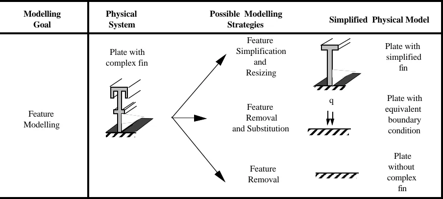
realistic to solve whilst at the same time preserves the essential integrity of the physical system. We consider construction of an analysis model to have two aspects; a physical perspective and a mathematical perspective [4]. Physical modelling focuses on spatial or geometric aspects of the problem domain and involve applying modelling strategies such as; taking a two dimensional idealisation of a three dimensional physical system, applying geometric symmetries or carrying out feature modelling. Strategies used in feature modelling, illustrated in Figure 1, can involve either replacing an existing complex feature with a simpler feature, removing the feature and substituting it with an equivalent boundary condition or removing the feature completely without any compensatory measures.
Plate with simplified
fin Modelling
Goal
Physical
System Simplified Physical Model
Feature Simplification
and Resizing
Plate with equivalent boundary condition Feature
Removal and Substitution
Plate without complex
fin Feature
Removal Plate with
complex fin
Possible Modelling Strategies
Feature Modelling
[image:2.595.62.514.164.367.2]q
Fig. 1 Feature modelling strategies
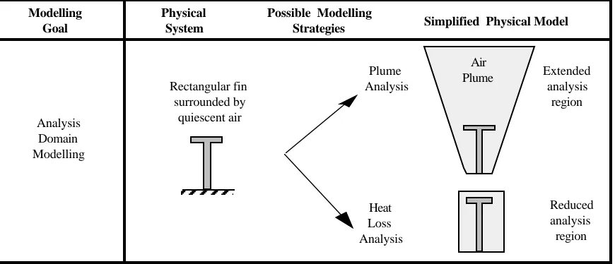
Mathematical modelling deals with the construction of a PDE model that describes the thermal heat transfer process. Considering the full thermal PDE, it consists of three sub-equations based on the physical laws of conservation of mass, momentum and energy. Each sub-equation is in turn composed of terms, where each term describes a particular sub-phenomenon. For example, in the energy equation, the diffusion term describes the heat transfer at a molecular level, the advection term describes heat transfer due to bulk motion of the fluid, whereas the viscous dissipation term describes the conversion of mechanical energy to thermal energy due to internal friction effects. In many heat transfer problems it is not necessary to model all these sub-phenomena and therefore terms can be either simplified or even be ignored completely. Another mathematical modelling task (illustrated in Figure 2) is the specification of an analysis volume that defines the extent of the fluid medium to be examined. Although this modelling task has spatial connotations, its specification is essentially governed by type phenomenological analysis that is required by the user.
3 Related Work, Conceptual Matters and Design Issues
3.1 Related work from heat transfer modelling
Modelling Goal
Physical
System Simplified Physical Model
Analysis Domain Modelling
Possible Modelling Strategies
Extended analysis region
Reduced analysis
region Plume
Analysis
Heat Loss Analysis Rectangular fin
surrounded by quiescent air
[image:3.595.70.505.62.249.2]Air Plume
Fig. 2 A subset of mathematical modelling issues
3.2 Conceptual Issues
In this work, particular attention was given to observing how engineers model convection heat transfer problems. These observations have strongly influenced the approach adopted and are reported elsewhere in detail [7]. The key findings are summarised here;
• Engineers usually model complex convection problems in distinct stages. These stages correspond to the physical and mathematical modelling issues outlined in Section 2 and are as follows; spatial modelling, phenomenological modelling, dimensional reduction, temporal modelling and control volume modelling. • Engineers exploit a number of techniques when modelling convection problems, these include; the use of first
principle domain knowledge to reason about modelling strategies, exploitation of previously modelled problems and relying on the guidance from more experienced colleagues. In most modelling episodes, a combination of these techniques are used.
• When investigating a particular modelling stage, e.g., spatial modelling, engineers usually decompose a complex physical system into easily understood sub-problems. These sub-problems are sufficiently low-level to be related to what we call classical engineering modelling scenarios. A scenario typically consists of simple modelling episodes and allow engineering approximations and heuristics to be applied, thereby permitting the modelling issue under consideration to be evaluated easily.
These conclusions influence our approach in two ways; firstly, for an interactive system it is imperative that we aim to accommodate the end-user and therefore the system should attempt to integrate with the modellling patterns used by engineers. Secondly, by capturing engineering first principles, engineering approximations and heuristics within fundamental classical modelling scenarios, it is possible to build a case based reasoning system that is based on episodic based templates that provide guidance for modelling tasks.
3.3 Design Approach adopted in this work
We summarise here our conceptual approach to modelling which forms the basis for the implemented CBR system.
• The system is organised so as to allow modelling to be carried out in distinct stages. In this paper, we consider the stage of spatial feature modelling.
• Within any modelling stage, modelling decisions are taken in a piece wise fashion by examining each modelling issue in turn.
• Case based reasoning with derivational analogy techniques form the core approach. Cases are based on fundamental modelling scenarios and are derived from episodic modelling events.
• Solutions within cases describe a model strategy that can be applied to similar target cases. The strategy is usually in form of some action which is in response to a particular modelling goal.
• Derivational traces describe the full engineering reasoning basis by which a particular modelling solution was reached. They also act as an explanation facility and validator of the case solution. More importantly however, they allow solutions of base cases that are close to the target case to be adapted and applied to the target.
4. Implementation Details
4.1 A Convection Heat Transfer Problem
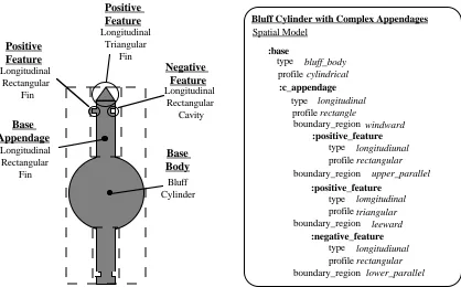
complex appendages are attached to the cylindrical base, each appendage has additional minor associated features. The modelling goal in this task is to assess the importance of both the minor features and the appendages themselves, this task corresponds to the spatial modelling phase described in Section 2.
Air Flow
10, 000 Reynolds
Number
20 Co Ambient
Temperature
Entry Temperature
Reynolds Number Water Flow
[image:4.595.174.398.109.271.2]2000 o 80 C
Fig. 3 A finned heat exchanger tube
4.2 Target Case Description
A target case consists of a frame based representation of the physical system. Within a target frame, representation is organised according to the different modelling perspectives; spatial modelling, phenomenological modelling and control volume analysis modelling. Figure 4 illustrates from a spatial perspective how the finned heat exchanger is classified and shows some of the indices used to describe the problem. In this case, a partonomic type relationship at three levels describes the essential components of the physical system, namely; the base cylinder, the complex appendages and their associated minor features. In this problem, the base is classified as a cylindrical bluff body in crossflow, the complex appendage is a rectangular longitudinal fin with features located on its windward, upper parallel and leeward sides. These features are a longitudinal rectangular cavity, a longitudinal triangular fin and a longitudinal rectangular fin. Problem parameters such as geometric data are also included in the target case but are not used as indices, however this information is used in the derivational traces.
4.3 Modelling Approach and Base Case Description
In Section 2, we argued that engineers normally model convection problems by decomposing the problem into well understood scenarios and considering each of these in a sequential manner. By classifying the heat exchanger problem as shown in Figure 4, this decomposition has been effectively achieved. Modelling progresses by firstly examining the role of the minor features with respect to the complex appendage and secondly the role of the complex appendage with respect to the cylindrical base. Each of these modelling episodes are sufficiently fundamental, so that they are comparable in terms of complexity and detail to the classical modelling scenarios discussed in Section 3. Consequently, all base cases are represented at this modelling abstraction level. Figure 5 illustrates one base case, that of modelling a longitudinal positive rectangular feature on the windward side of a rectangular fin. This base case is a classical heat transfer situation, is well understood and can be adapted and applied to a range of similar problems. In this base case, qualitative indices describe the minor feature and the associated base appendage. The modelling action or solution associated with this base case is that the feature can be removed completely without the need for any compensatory action. However, this action is not applied directly but is instead implemented by a process of regenerative transformation by applying the associated derivational trace.
4.4 Matching and Mapping
Base Body
Bluff Cylinder Longitudinal
Rectangular Fin
Base Appendage
Positive Feature
Longitudinal Rectangular
Fin
Positive Feature
Longitudinal Triangular
Fin
Negative Feature
Longitudinal Rectangular
Cavity
Bluff Cylinder with Complex Appendages Spatial Model
:base
:c_appendage type
profile
bluff_body cylindrical
type profile
longitudinal rectangle
boundary_region
boundary_region
boundary_region
boundary_region
windward
upper_parallel
leeward
lower_parallel
:positive_feature
longitudiunal
type
rectangular
profile
:positive_feature
lomgitudinal
type
triangular
profile
:negative_feature
longitudiunal
type
rectangular
[image:5.595.64.482.60.320.2]profile
Fig. 4 A spatial classification of the problem with a partial description of the associated target case.
4.5 Derivational Traces
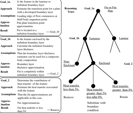
Derivational traces are exploited in this domain, because, although the target and base cases may map qualitatively, small differences between physical parameters such as spatial or medium data can lead to significantly different solutions. Such differences cannot be expected to be captured in the initial qualitative classification of the problem, furthermore, to index all episodes based on both descriptive and parametric indices would result in an intractably large case base. A derivational trace describes the basis of the modelling solution, in this example, the removal of a windward longitudinal feature on a rectangular appendage, the reasoning behind these decisions and the engineering approximations and heuristics used in the evaluation process. In this example, the solution in the base case was derived in two ordered stages; firstly, the influence of the feature on the medium flow field was determined and found to be negligible and secondly the contribution of the feature to total appendage heat transfer was assessed and found to be of minor importance. Figure 6 shows a simplified version of the derivational trace. The fist stage examines the influence of the feature on the flow field and consists of Goals 1a and 1b. This involves determining whether the feature is actually fully contained within a turbulent boundary layer, and if so, the influence of the feature on the flow field is deemed negligible. Goal 2examines the contribution of the feature to overall heat transfer. In the base case, the heat transfer contribution of the feature was of the order of 4% of total heat transfer well within the 5% constraint, so therefore the fin was be removed, in the target case, this contribution was of the order of 3.5% thereby permitting the feature to be removed.
Rectangular Appendage with Fin
direction: windward
:positive_feature type flat plate
type profile
longitudinal rectangular aft
location
flow_regime turbulent
Description Solution
Action Remove fin
Compensation None
Derivational Trace
[image:5.595.120.450.589.719.2]5. Conclusions
We have described a preliminary prototype of an interactive case based reasoning tool for mathematical modelling of thermal engineering problems. Derivational analogy techniques are exploited to provide for generative adaption and validation of base cases. We have found that because of the complexity of the domain, derivational analogy techniques are necessary to provide for case adaption and validation. Nevertheless we believe that this work represents an interesting if not significant alternative perspective to model based reasoning approaches that have been applied to model generation to date.
Goal_1a Is the feature in the laminar or turbulent boundary layer
Estimate the transition point for a plate with a developed boundary layer Leading edge of flow commences at bluff body stagnation point.
Turbulent Laminar
Fin on Flat Plate
Enclosed
Non-Enclosed Goal_2
Remove Retain
Substitute with boundary condition Heat transfer
less than 5% Heat transfer greater than 5% less tahn 8%
Heat transfer greater than 8% Reasoning
Trace Approach
Assumptions
Fin is located in a turbulent boundary layer Result
Goal_1b Is the feature enclosed by the turbulent boundary layer Calculate the turbulent boundary layer thickness
That the boundary layer thickness estimator can be used for a composite body composition
Approach
Assumptions
Fin is completely within turbulent boundary layer Result
Goal_1b => Flat plate transition point approximation
Approx- imation
Approx- imation
Boundary layer thickness approximation
=>
Goal_2 Determine the contribution of heat transfer of the feature
Estimate the heat transfer associated with the feature
That the fin apporximations are applicable in this case
Approach
Assumptions
Fin heat trabsfer is less than 5%
Result Approx-
imation Fin Approximations
Remove =>
Goal_1a
Goal_1b
[image:6.595.69.502.168.535.2]Goal_2
Fig 6 A derivational trace for a windward finned appendage
References
1. K. Bathe, N. Lee, M. Bucalem: On the use of hierarchical models in engineering analysis. Computer Methods in Applied Mechanics and Engineering, 82(1-3), pp. 5-26, 1990.
2. M. Shephard, P. Baehmann, M. Georges, E. Korngold: Framework for reliable generation for the control of analysis idealisations. Computer Methods in Applied Mechanics and Engineering, 82 (1-3), pp. 257-280, 1990. 3. Carbonell J.G: Derivational Analogy: A theory of reconstructiuve problem solving and expertise acquisition. In:
R.S. Michalski, J.G, Carbonell, T.M. Mitchell (eds)., Machine Learning, 2 pp , 371-392, 1986.
4. D. Finn, J.B. Grimson, N. Harty: An intelligent modelling assistant for preliminary analysis in design: In: J. Gero (ed) Proc. of the 2nd International Conference on Artificial Intelligence in Design, pp 579 - 596, Carnegie Mellon University, Pittsburgh, June 1992.
5. S. Ling, L. Steinberg. Approximation operators in distributed computing: In: D. Weld (ed): Working Papers Qualitative Reasoning '93 (QR '93). Seattle: University of Washington 1993, pp. 138-144.
6. K. Yip: Model simplification by asymptotic order of magnitude reasoning. In: D. Weld (ed): Working Papers Qualitative Reasoning '93 (QR '93). Seattle: University of Washington 1993, pp. 266-272.