Time- and frequency-domain spreading assisted MC DS-CDMA using interference rejection
spreading codes for quasi-synchronous communications
Hua Wei, Lie-Liang Yang and Lajos Hanzo
½School of ECS, University of Southampton, SO17 1BJ, UK.
Tel: +44-23-8059-3125, Fax: +44-23-8059-4508
Email:lh
½@ecs.soton.ac.uk
,
http://www-mobile.ecs.soton.ac.uk
Abstract
In this contribution we considered a Time-Frequency (TF)-domain spreading aided MC DS-CDMA system, which employed so-called generalized orthogonal spreading codes exhibiting an interference free window (IFW). Provided that the propagation delay differ-ences of the different users are with in this IFW, no multiuser in-terference is inflicted, and hence a near-single-user performance may be attained without invoking a multiuser detector. As an additional benefit, the proposed MC DS-CDMA system is capa-ble of extending the width of IFW in comparison to a conven-tional DS-CDMA system. Furthermore, it is capable of achieving a significantly higher frequency diversity gain in comparison to a single-carrier DS-CDMA system while reducing the MUD’s com-plexity.
1. INTRODUCTION
In the context of code-division multiple-access (CDMA) communica-tion, there are two fundamental types of spread-spectrum schemes. The first scheme spreads the original data stream in the time (T)-domain [1, 2], while the second in the frequency (F)-(T)-domain, resulting in the scheme known as MC-CDMA [3–5]. In [6], an amalgam of the above spreading schemes has been developed. Explicitly, the origi-nal data stream is spread not only in the T-Domain, but also in the F-domain. Hence each user is assigned two spreading sequences for this operation, namely a T-domain and a F-domain sequence. This system exhibits a high flexibility as well as a reduced Multiuser De-tection (MUD) complexity. In [6], several TF-domain spreading as-sisted MC DS-CDMA MUD schemes have been considered. How-ever, the complexity imposed may become excessive, when the num-ber of users supported is high. In this contribution, we will consider the employment of two specific families of spreading codes as the T-domain spreading code, which are known as generalized orthogonal codes [7]. These codes exhibit a so-called Interference Free Window (IFW). Over the duration of the IFW both the cross-correlation and the auto-correlation of the spreading codes is zero. The benefit of employing these specific codes as the T-domain code is that we are capable of reducing the complexity of the MUD, while achieving a frequency diversity gain. Specifically, the MUD’s complexity is re-duced because only a small fraction of the total number of users has to be separated and detected by the MUD, which belong to a given MUD group. By contrast, the set of users which are differentiated with the aid of unique user-specific spreading codes having an IFW do not interfere with each other, as a benefit of the IFW provided by the T-Domain codes used. Another advantage of the proposed scheme is that we can significantly extend the width of the IFW in compar-ison to a single-carrier DS-CDMA system, because as a benefit of
The financial support of the Mobile VCE, UK; the EPSRC UK and that of the European Union is gratefully ackowledged.
distributing the bits to serval subcarriers, MC DS-CDMA has the po-tential of significantly reducing the chip rate, thereby extending the duration of the chips. This also allows us to extend the width of the IFW, which renders the system more insensitive to timing imperfec-tions, since larger timing errors can be accumulated without imposing interference.
This report is organized as follows. Sections 2 will briefly de-scribe the family of generalized orthogonal codes. Section 3 char-acterises the philosophy of TF-domain spreading in the context of MC DS-CDMA signals. Section 4 considers two different correlation based detection schemes, while in Section 5 we discuss the benefi-cial features of this specific system. Finally, in Section 6 we provide simulation results for characterising different generalized orthogonal codes, while in Section 7 we present our conclusions.
2. GENERALIZED ORTHOGONAL CODES
Since the basic properties of generalized orthogonal codes have been characterized in [7], we will concentrate our attention on procedures used for creating generalized orthogonal codes. Firstly, we define a sequence set
, where
is a
spreading sequence having a length of. The spreading codes result in an IFW width ofIFW, if the crosscorrelation of the spreading codes satisfies:
mod
IFW
(1) The family of generalized orthogonal binary codes is generated from a pair of so-called complementary sequences also referred to as mates [8, 9], which can be recursively generated as follows:
(2)
(3)
Hence, the length of is , and for a given com-plementary sequence pair , we can construct theth order generalized orthogonal code’s mother matrix
, which can be ex-pressed as [7]:
(4)
where
is generated by reversing the order of the sequence , while is the negated version of . Each row of the mother matrix
constitutes a spreading sequence, hence two spreading se-quences are hosted by the matrix
. Once we obtained the mother matrix
, the so-called th-order generalized orthogonal code’s matrix can be recursively generated according to:
where denotes an operation referred to as interleaving, and the interleaving interval is
. For the example of two vectors,
namely for , and
for the interleaving interval ofwe have:
(6)
For simplicity, we denote theth-order generalized orthogonal codes as , whereis the length of generalized orthogonal code,
is the number of the codes generated andis the width of the IFW.
Explicitly, we have
. As an example, we consider complementary pairs, which can be obtained with the aid of Equation 2 and 3 as follows:
Once we obtained the complementary pair , we can con-struct the 0th-order mother matrix
according to Equation 4, and the matrixof the codes can be constructed according to Equation 5, while the interleaving interval is
. Therefore, following the interleaving operation, the spreading code
can be constructed as:
0 10 20 30
[image:2.595.342.516.48.167.2] [image:2.595.44.288.280.469.2]-30 -20 -10 0 10 20 30
|Autocorrelation|
offsets[chip]
(a) Autocorrelation
0 10 20 30
-30 -20 -10 0 10 20 30
|Crosscorrelation|
offsets[chip]
(b) Crosscorrelations
Figure 1: The auto- and cross-correlation magnitudes of the
codes. (a) All four codes of the family exhibit the same autocorrelation magnitude. (b) The crosscorrelation magnitudes of the four codes are also identical.
All four different codes of thefamily exhibited the same autocorrelation magnitudes, namely that seen in Figure 1(a). It can be observed in Figure 1(a) that the off-peak autocorrelation
becomes zero for. The crosscorrelation magnitudes
depicted in Figure 1(b) are also zero for. From the observations made as regards to the aperiodic correlations we may conclude that thecodes exhibit an IFW within an offset duration ofchip intervals.
Furthermore, we can shorten the generalized orthogonal code set
for creating a new generalized orthogonal code set ¼
¼
¼
, where we have
¼
¼
, provided that we have . This shortening operation will reduce the code length, however, it also reduces the widthIFW of the interference free window. Our general objective is to maximize the relative duration of the IFW in comparison to the code length, while generating the highest possible number of codes. Broadly spread-ing this allows us to support the highest possible number of users without imposing multiuser interference.
. . . .
Figure 2: Transmitter model of MC DS-CDMA using both time-domain and frequency-time-domain spreading. T-domain spreading is achieved using the code and each chip ofis spread in the frequency-domain by mapping it tosubcarriers, each carrying one of theF-domain chips.
3. SYSTEM MODEL
The transmitter schematic of the MC DS-CDMA scheme using both T-domain and F-domain, i.e. TF-domain spreading is shown in Fig.2 in the context of theth user. At the transmitter side, the binary data streamis first direct-sequence (DS) spread using the T-domain signature sequence
. Following T-domain spreading, the T-domain DS spread signal is divided intoparallel branches, where each branch-signal is multiplied by a corresponding chip value of the F-domain spreading sequence
of length. Following F-domain spreading, each of thebranch sig-nals modulates a subcarrier frequency using binary phase shift keying (BPSK). Then, the number of subcarrier-modulated substreams are added in order to form the transmitted signal. Hence, the trans-mitted signal of usercan be expressed as
(7)
whererepresents the transmitted power of each user and
represents the subcarrier frequency set. The binary data
stream’s waveform ½
consists of a sequence of mutually independent rectangular pulses
of duration and of amplitude +1 or -1 with equal probabil-ity. The spreading sequence
½
denotes the T-domain spreading sequence waveform of the th user, whereis the rectangular chip waveform, which is de-fined over the interval . We assume that the T-domain spread-ing factor is , which represents the number of chips per bit-duration. Furthermore, we assume that the subcarrier signals are orthogonal and the spectral main-lobes of the subcarrier signals are not overlapping with each other.
We assume that quasi-synchronous
1 TF-domain spread MC
DS-CDMA signals obeying the form of (7) are transmitted over the uplink frequency selective channel, but each subcarrier of each user experiences statistically independent single-path flat Rayleigh fading. Hence, theth subcarrier’s Channel Impulse Response (CIR) can be written as! "
, where
the amplitude! is a Rayleigh distributed random variable and the
1Quasi-synchronous in this context implies that the delay-differences of the
Group MUD
Ê
Ê
Ê
Ê
Ê
Ê
[image:3.595.71.259.55.238.2]
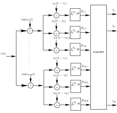
Figure 3: Receiver model of MC DS-CDMA using both time-domain and frequency-domain spreading.
phase# is uniformly distributed between$. We also assume furthermore that each user experienced a different delay of, which obeys
IFW. This can be achieved by invoking a Global Po-sitioning System (GPS) assisted synchronization protocol. Then the received signal may be expressed as:
!
# (8)
whererepresents the AWGN having zero mean and double-sided power spectral density of
. Moreover, let
and
be thenumber of T-domain spreading sequences andnumber of F-domain spreading sequences, respectively, where
% represents a F-domain spreading code. Furthermore, we
as-sume that the number of active users is. We also introduce a new variable of , where&represents the smallest integer not less than&, for denoting the number users associated with a spe-cific T-domain code, which are differentiated by a unique F-domain code. Then, we have , since the total number of users is less than the product of the T-domain and F-domain spreading factor,
i.e. we have and . Based on the above assump-tions, thenumber of users supported can be grouped intouser groups, with each group supporting at most users. Consequently, it can be readily shown that each of the user groups can be dis-tinguished by assigning one of thenumber of T-domain spreading sequences.
As shown in Fig.2 and Equation (7), each TF-domain spread MC DS-CDMA signal is identified with the aid of two spreading sequences, one applied in the context of the T-domain and one in the F-domain. In the following sections we will analyze the detection of TF-domain spread MC DS-CDMA signals by invoking two different detection schemes. Specifically, in Section 4 we used both Maximum Ratio Combining (MRC) as well as a low-complexity Maximum Likelihood (ML) decision based MUD.
4. DETECTION SCHEMES
In this section we will discuss the receiver model of the MC DS-CDMA schemes employed, which is shown in Fig 3. We consider
a correlation-based receiver, which essentially carries out the inverse operation seen in Fig 2. In Fig 3 the output variable correspond-ing to theth subcarrier of theth user can be expressed as:
'
(9)
According to [10], the received signal vector at the output of the bank of matched filters related to the th subcarrier can be expressed as:
( (
(10)
where we have:
diag
diag! "
! "
is the time index,
(11)
and the zero-mean Gaussian noise vector has the crosscorrelation matrix of:
)
*
if
*
if
*
if
+" ,"
(12)
The partial crosscorrelation matrixand the crosscorrelation matrixof the T-domain spreading codes, when communicating over an asynchronous channel, are defined as [10]:
if
- if
- if.
(13)
if
- if
(14)
where the coefficients- and
are the pair of crosscorrelations of the spreading codes recorded in the asynchronous CDMA system considered, which can be written as [10]:
' (15)
' (16)
However, in our system the time-domain spreading codes are gener-alized orthogonal codes, which exhibit an IFW. Therefore, the partial cross-correlation matrixis an all-zero matrix, provided that the delay differences obey
IFW . Hence, Equa-tion 10 can be simplified to:
(17)
In Equation 17 we can ignore the time indexin the superscripts. Hence, Equation 17 can be written as:
4.1. Low-Complexity Multiuser Detection
Let us now interpret Equation 18 in more detail. In Section 3 we have divided the number of users supported into user groups, each group havingusers, which are distinguished by their time-domain spreading code
. In this scenario, the system activates time-domain spreading codes and frequency-domain spreading codes. Therefore, provided that both theth andth user’s delay is within the range of the IFW and theth user andth user are in the same group, the element-of the correlation-matrixof Equation 18 will satisfy- . More specifically, in this system each user will encounter Multiple Access Interference (MAI) imposed by a reduced number of users, rather thanusers, since all these users of each of the user groups employ the same T-domain spreading code but a different F-domain spreading code. Therefore, we have to detect a reduced number of , rather thanusers, which facili-tates the employment of low-complexity Multiuser Detection (MUD). For example, let us consider the first user in the context of supporting a total of users. Then the first user encounters interfer-ence inflicted by theth,, th user, because they share the same T-domain spreading code, but they are identified by the different F-domain spreading codes. Hence, Equation 18 can be simplified as:
(19)
where we have:
Ã
diag Ã
diag! "
! "
!Ã "
Ã
Ã
-Ã
- - -Ã
..
. ... ... ...
-Ã
-Ã
-ÃÃ
(20)
The Maximum Likelihood (ML) decision based MUD of theth sub-carrier has to evaluate:
arg
(21)
where
denotes the Euclidean norm. Upon combining all the subcarriers, the ML based MUD’s decision function can be written as:
arg
(22)
According to Equation 22, the complexity of the ML decision based MUD invoked in the context of the TF-domain spreading assisted MC DS-CDMA system is on the order of
Ã
, rather than on Ã
. Let us now briefly summarize the basic features of the system considered, before we characterize the achievable system performance.
5. CHARACTERISTICS OF TF-DOMAIN SPREADING ASSISTED MC DS-CDMA EMPLOYING GENERALIZED ORTHOGONAL CODES AND LOOSELY SYNCHRONIZED
CODES
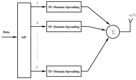
The system considered in Figure 2 of the previous section can be extended by using/ number of subcarriers. Specifically, as it is shown in Fig 4, the original serial data stream is first subjected
TF−Domain Spreading
Data
TF−Domain Spreading
TF−Domain Spreading S/P
½
¾
Í
״ص
[image:4.595.314.545.49.186.2]
Figure 4: Transmitter model of MC DS-CDMA using serial to parallel conversion.
to serial to parallel conversion, resulting in/ independent parallel data streams. Moreover, each parallel data stream is further spread to
subcarriers using the TF-domain spreading philosophy of Fig 2. The subcarriers are arranged for maintaining the maximum pos-sible frequency spacing, so that they experience independent fading and hence achieve the maximum possible frequency diversity gain. Specifically, let
be the/number of subcarrier frequencies, where each of the/ parallel bits is spread according to the following/-dimensional matrix:
..
. ... . .. ...
(23)
Therefore, the chip rate of the MC DS-CDMA signal can be reduced by a factor of/and hence the width of the IFW can be extended by a factor of/ in comparison to a DS-CDMA system, which can be expressed as:
/ (24)
Based on Equation 24, we argue that the width of the interference free window of MC DS-CDMA systems may be significantly higher than that of DS-CDMA. This beneficial feature allows us to have sig-nificantly larger cells, which result in higher propagation delay dif-ferences and/or allows the system to reliably operate even in case of higher absolute code synchronization errors, as long as they do not exceed the IFW width.
Another advantage of this system is that it is capable of achiev-ing a high frequency diversity gain, because the chips of each bit are transmitted on independently fading subcarriers. Hence, when the transmitted signal experiences frequency selective fading, the chances are that only some of the chips of a F-domain spreading code are cor-rupted and therefore the corresponding bit conveyed by the specific spreading code concerned may still be recovered. Consequently this system may be capable of achievingth-order F-domain diversity and benefit from a factor of
à Ã
lower multiuser detection complexity.
6. SIMULATION RESULTS
matrix given by:
(25)
Furthermore, we considered four different T-domain spreading codes, which are the, , where again, gener-alized orthogonal codes are defined with the aid of the parameters
, withbeing the length of the code,being the num-ber of codes generated and being the IFW width. Moreover, we assume that each subcarrier of each user experienced independent flat Rayleigh fading.
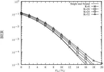
From Figures 5 and 6, we can observe that the low-complexity MUD is capable of approaching the single-user bound.
7. CONCLUSION
In this report, we employed a specific family of spreading codes, which exhibit an interference free window in the context of the TF-domain spreading assisted MC DS-CDMA system considered. In this system we reduced the complexity of the MUD by a factor of
à Ã
, while achievingth-order frequency diversity. The system is capable of significantly extending the width of the interfer-ence free window as a benefit of the serial to parallel conversion in-voked in Figure 4, which additionally renders the system insensitive to timing imperfections.
0 2 4 6 8 10 12 14 16 18 20
Single user bound K=8 K=16 K=24 K=32
BER
[image:5.595.319.536.53.210.2]
Figure 5: BER performance of the TF-domain spreading aided MC DS-CDMA system in conjunction with low-complexity MUD, while employing the generalized orthogonal code as the T-domain spreading code. The F-T-domain spreading code was a -dimensional Walsh code, and each of the subcarriers experi-enced independent narrowband Rayleigh fading. The MUD complex-ity reduction factor was
.
8. REFERENCES
[1] A. Viterbi, Principles of Spread Spectrum Communications. ISBN 0201633744, Addison-Wesley, Aug 1995.
[2] R. L. Peterson, R. E. Ziemer, and D. E. Borth,Introduction to Spread Spectrum Communications. Prentice Hall International Editions, 1995.
[3] R. Prasad and S. Hara, “Overview of multicarrier CDMA,”IEEE Communications Magazine, pp. 126–133, December 1997.
0 2 4 6 8 10 12 14 16 18 20
Single user bound K=4 K=8 K=12 K=16
BER
[image:5.595.54.275.351.505.2]
Figure 6: BER performance of the TF-domain spreading aided MC DS-CDMA system in conjunction with low-complexity MUD, while employing the generalized orthogonal code as the T-domain spreading code. The F-T-domain spreading code was a -dimensional Walsh code, and each of the subcarriers experi-enced independent narrowband Rayleigh fading. The MUD complex-ity reduction factor was
.
[4] R. Prasad and S. Hara, “Overview of multi-carrier CDMA,” in
Proceedings of the IEEE International Symposium on Spread Spectrum Techniques and Applications (ISSSTA), (Mainz, Ger-many), pp. 107–114, 22–25 September 1996.
[5] L. Hanzo, M. M¨unster, B. J. Choi, and T. Keller,OFDM and MC-CDMA. John Wiley and IEEE Press, May 2003.
[6] L. Hanzo, L. L. Yang, E. L. Kuan, and K. Yen,Single- and Multi-Carrier CDMA. John Wiley and IEEE Press, Jul. 2003.
[7] P. Fan and L. Hao, “Generalised Orthogonal Sequences and Their Applications in Synchronous CDMA Systems,” IEICE Transaction on Fundamentals, vol. E83-A, pp. 2054–2069, Nov. 2000.
[8] C.-C. Tseng and C. L. Liu, “Complementary Sets of Sequences,”
IEEE Transactions on Information Theory, vol. 18, pp. 644– 652, Sep. 1972.
[9] R. Sivaswamy, “Multiphase Complementarty Codes,” IEEE Transactions on Information Theory, vol. 24, pp. 546–552, Sep. 1978.