Tandon TM 100 1 Flexible Disk Drive pdf
Full text
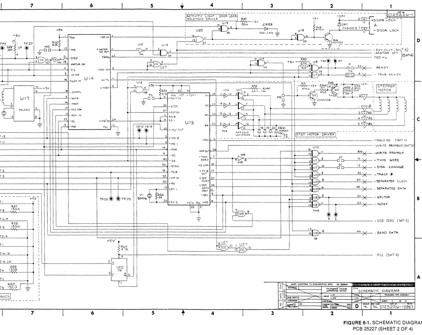
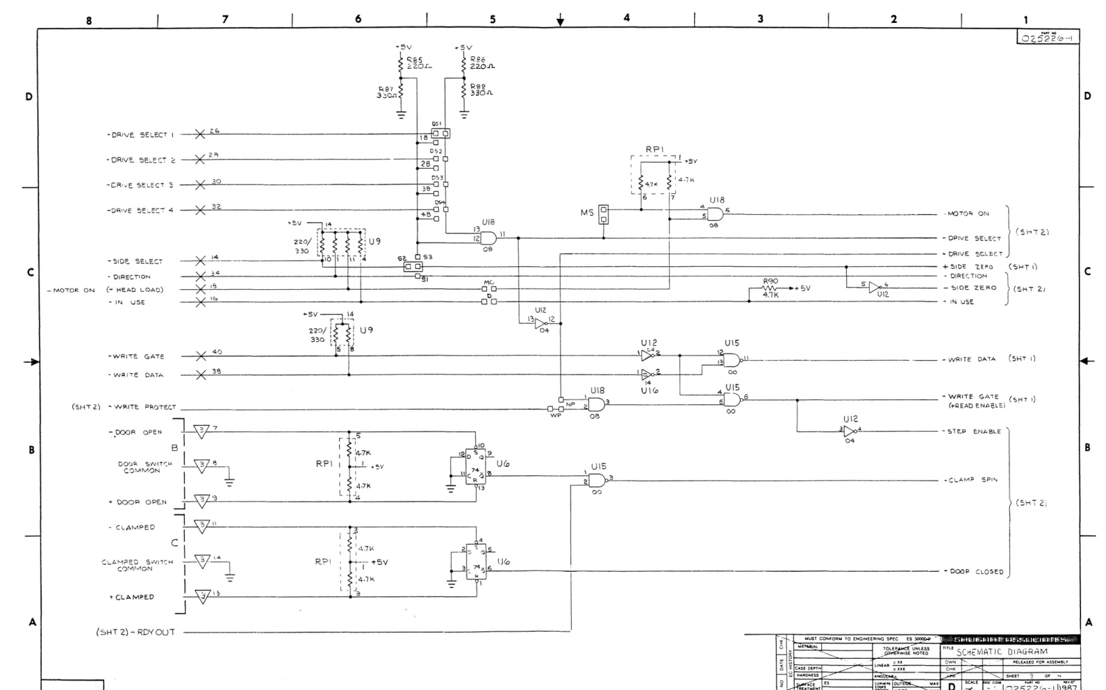
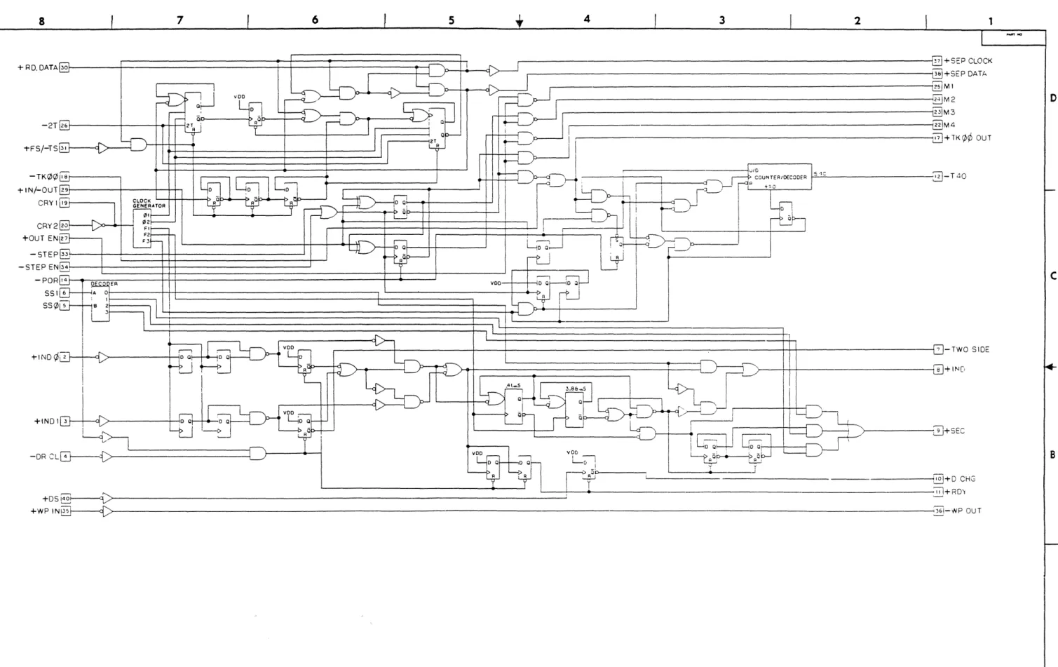
Figure


Related documents
This high-active 8-bit wide bus is used to transfer commands and status (head carriage control and interface) between the disc drive and the controller.. These lines
This bit indicates that the selected physical drive has finished seeking and that the heads are settled on track ready for a read or write operation.. This bit
As an alternative, SATA line 0 is dedicated to an optional on-board 1.8-inch hard disk drive by means of the on-board Serial ATA to Parallel ATA bridge.. SATA line 1 is
For a normal read or write sector operation, the Sector Number, the Size/Drive/Head, Cylinder Number and Command register (usually in that order) will be
For a normal read or write sector operatlon, the Sector Number, the Size/Drive/Head, Cylinder Number and Command register (usually in that order) will be
Also, the write gate signal functions to cause tunnel erase to take place inside the drive, hence neither side select nor step head unload will take place until 1.2 ms after
The receiver active circuit monitors the serial received data line from the peripheral interface and a receiver done (RDONE H) status bit from the RBUF.. The
When the Head Load (HLD) or Motor On (MTON) line, and Drive Select (DS) lines are asserted by the host controller, the capstan on the selected drive is enabled and tape motion
