SCSI
Development
System
Reference
Manual
SDS-1
Revision 1.2
August
1986
Table of Contents
Section
INTRO.0 SDS-I INTRODUCTION ••••.••••.••••••••••••••••••••••• INTRO.l SDS-l Overview ••••••••••••••••••••••••••••••••••• INTRO.2 SDS-l Product Design Goals ••••••••••••••••••••••• INTRO.3 SDS-l Development System Product Features •••••••• INTRO.4 System Components •••••••••••••••••••••••••••••••• INTRO.S Using The SDS-l •••••••••••••••••••••••••••••••••• INTRO.S.l SDS-I Architectural Concepts ••••••••••••••••• INTRO.S.l.l Buffers •••••••••••••••••••••••••••••••••• INTRO.S.l.2 Hardware Compare ••••••••••••••••••••••••• INTRO.S.l.3 I/O Driver/MENU Execution Environment
INTRO. G Help System ••••••••••.•••••••••••••••••••••••••••
MENU.0 MENU INTERFACE
MENU. 1 Introduction/Overview ••••••••••••••••••••••••••••• MENU.l.l Parameter Setup in Edit Mode •••••••••••••••••• MENU.l.2 Function Execution •••••••••••••••••••••••••••• MENU.l.3 Trace Display ••••••••••••••••••••••••••••••••• MENU.l.4 Setting Error Action •••••••••••••••••••••••••• MENU.I.S Menu Interface States ••••••••••••••••••••••••• MENU.2 SETUP Menu •••••••••••••••••••••••••••••••••••••••• MENU.2.1 Execute All Function ••••••••••••••••••••••••••
MENU.3 BUFFER .Menu •••••••••••••••••••••••••••••••••••••••
MENU.4 RANDOM Menu • • • • • • • • • • • • • • • • • • • • • • • • • • • • • • • • • • • • • • •
MENU.S SEQUENTIAL Menu ••••••••••••••••••••••••••••••••••• MENU.6 OTHER I/O DRIVER Menu •••••••••••••••••••••••••••••
MENU.7 MP Menu • • • • • • • • • • • • • • • • • • • • • • • • • • • • • • • • • • • • • • • • • • •
MENU.?l Display SCSI Bus Function •••••••••••••••••••••
MENU.8 FKEY Men u • • • • • • • • • • • • • • • • • • • • • • • • • • • • • • • • • • • • • • • • •
MENU.S.l Function Key Selection •••••••••••••••••••••••• MENU.S.I.l Display/Edit/Append Modes ••••••••••••••••• MENU.S.I.I.l Display Mode •••••••••••••••••••••••••• MENU.S.l.I.2 Append Mode ••••••••••••••••••••••••••• MENU.S.1.1.3 Edit Mode ••••••••••••••••••••••••••••• MENU.S.1.1.4 Return to FKEY Menu ••••••••••••••••••• MENU.S.2 Save/Load FKEY Set Functions •••••••••••••••••• MENU.S.2.1 Save FKEY Set Function •••••••••••••••••••• MENU.S.2.2 Load FKEY Set Function •••••••••••••••••••• MENU.S.3 Debugger State •••••••••••••••••••••••••••••••• MENU.S.4 FKEY Execution Loop Count ••••••••••••••••••••• MENU.S.S Stopping FKEY Sequence Execution •••••••••••••• MENU. 90TH ER/ EX I T Menu ••••••••••••••••••••••••••••••••••• MENU.9.1 Save Parameters Function •••••••••••••••••••••• MENU.9.2 Load Parameters Function •••••••••••••••••••••• MENU.9.3 Save and Exit Function •••••••••••••••••••••••• MENU.9.4 Exit Function ••••••••••••••••••••••••••••••••• MENU.9.S Screen Swap Function •••••••••••••••••••••••••• MENU.9.G Initial Menu Screen Display Function •••••••••• MENU.9.? Trace Function ••••••••••••••••••••••••••••••••
Table of Contents
Section Page
MENU.10 Menu Interface Errors •••••••••••••••••••••••••••• MENU-16 MENU.10.l No Space for Parameters •••••••••••••••••••••• MENU-16 MENU.10.2 No Space for Function •••••••••••••••••••••••• MENU-16 MENU.l0.3 File I/O Error ••••••••••••••••••••••••••••••• MENU-16 MENU.l0.4 Version Mismatch ••••••••••••••••••••••••••••• MENU-17 MENU.10.S Maximum Number of Functions •••••••••••••••••• MENU-17 MENU.10.6 Incompatible File Types •••••••••••••••••••••• MENU-17 MENU.10.7 File Does Not Exist •••••••••••••••••••••••••• MENU-17 MENU.10.8 Error in Converting File ••••••••••••••••••••• MENU-17 MENU.10.9 PC Mouse Not Installed ••••••••••••••••••••••• MENU-17 MENU.10.10 Temporary Files Have Not Been Deleted ••••••• MENU-18 MENU.10.l1 File Name Error ••••••••••••••••••••••••••••• MENU-18 MENU.10.l2 Invalid String Pointer; Memory Not Freed •••• MENU-18 MENU.ll Mouse Operations with the Menu Interface ••••••••• MENU-18
SAT.0 STAND-ALONE TEST (SAT) GENERATION PROCESS •••••••••••• SAT-I SAT.l Introduction ••••••••••••••••••••••••••••••••••••••• SAT-l SAT.2 SAT Design and Coding •••••••••••••••••••••••••••••• SAT-3 SAT.2.1 User Template For SAT •••••••••••••••••••••••••• SAT-3a SAT.2.2 SAT Program Creation ••••••••••••••••••••••••••• SAT-S
SAT.2.2.1 "C" Notes •••••••••••••••••••••••••••••••••• SAT-8 SAT.2.3 Test & Documentation Function Library •••••••••• SAT-8 SAT.2.4 Compilation and Linkage of SAT ••••••••••••••••• SAT-9 SAT.3 SAT Debug •••••••••••••••••••••••••••••••••••••••••• SAT-16
SAT.3.1 Command Tail Operator -DB= ••••••••••••••••••••• SAT-16 SAT.3.l.l Debug Level 0 •••••••••••••••••••••••••••••• SAT-17 SAT.3.1.2 Debug Levell •••••••••••••••••••••••••••••• SAT-18 SAT.3.l.3 Debug Level 2 •••••••••••••••••••••••••••••• SAT-l9 SAT.3.l.4 Debug Level 3 •••••••••••••••••••••••••••••• SAT-20 SAT.3.2 Command Tail Operator -PR •••••••••••••••••••••• SAT-21 SAT.4 Library Cataloging ••••••••••••••••••••••••••••••••• SAT-2l SAT.S Error Handling Logic ••••••••••••••••••••••••••••••• SAT-21 SAT.6 SAT Execution Halt/Interruption •••••••••••••••••••• SAT-22 SAT.6.l Normal End of SAT Program •••••••••••••••••••••• SAT-22 SAT.6.2 ESCAPE Key ••••••••••••••••••••••••••••••••••••• SAT-22 SAT.6.3 CONTROL-BREAK Keys ••••••••••••••••••••••••••••• SAT-22
DV.0 DESIGN VERIFICATION PROCESS ••••••••••••••••••••••••••• DV-l DV.l Introduction •••••••••••••••••••••••••••••••••••••••• DV-l DV.2 Design Verification Results ••••••••••••••••••••••••• DV-I DV.2.l Test Results Documentation •••••••••••••••••••••• DV-2 DV.2.2 Test Procedure Documentation •••••••••••••••••••• DV-4
Table of Contents
Section
RPTG.0 REPORT GENERATOR
RPTG.1 Introduction ••••••••••••••••.••••••••••••••••••••• RPTG.1.1 Architecture ••••••••••...••••••..••••••••••••• RPTG.1.2 Basic Operation ••••••••••••••••••••••••••••••• R P T G. 1 • 2 • 1 Te s t Res u 1 t s Re p 0 r t •••••••••••••••••••••••
RPTG.1.2.2 Test Procedures Report •••••••••••••••••••• RPTG.2 Report Generator Operators •••••••••••••••••••••••• RPTG.2.1 Input File Operators (Test Procedure Report) •• RPTG.2.1.l Global Operators ••••.••••••••••••••••••••• RPTG.2.1.1.1 Documentation Boundary (-DB=) ••••••••• RPTG.2.1.1.2 Start/Stop Document Output Operator ••• RPTG.2.l.1.3 Start/Stop Code Output Operator (-COD) RPTG.2.1.2 Documentation Line Mode Operators •••••••••
RPTG.2.1.2.1 Start/Stop Revision Log Output (-REV) • RPTG.2.1.2.2 Group Title Operator (-GT=) ••••••••••• RPTG.2.l.2.3 Paragraph Title Operator (-PT=) ••••••• RPTG.2.1.2.4 Page Eject Operator (-.PA) •••••••••••• RPTG.2.l.2.S Art Insert Operator (-AI=) •••••••••••• RPTG.2.1.2.S.1 Mouse Hardware Setup •••••••••••••• RPTG.2.1.2.S.2 Mouse Software Setup ~ ••••••••••••• RPTG.2.1.2.S.3 Mouse Drawing or Painting ••••••••• RPTG.2.1.2.S.4 Saving the Picture •••••••••••••••• RPTG.2.1.2.S.S Exit PC PAINT PLUS and Return ••••• RPTG.2.1.2.S.6 Using the Art Insert Operator ••••• RPTG. 2.1.3 Code Line Mode Operators ••••• : ••••••••••••• RPTG.2.1.3.1 Page Eject Operator (-.PA) •••••••••••• RPTG.2.1.4 Revision Log Line Mode Operato'rs •••••••••• RPTG.2.1.4.1 Page Eject Operator (-.PA)· •••••••••••• RPTG.2.2 Batch File Operators ••••••••••••• ; ••••••••••••• RPTG.2.2.1 Initial Setup ••••••••••••••••••••••••••••• RPTG.2.2.1.1 Documentation Title and Header (-TI=) • RPTG.2.2.1.2 Creation Date (-CD=) •••••••••••••••••• RPTG.2.2.1.3 Reference Number or Name (-RN=) ••••••• RPTG.2.2.1.4 Filename Output (-FO=) •••••••••••••••• RPTG.2.2.2 Specifiy File Name (Test Procedures Report)
RPTG.2.2.2.1 File Name Operator (-FN=) .••••••••••••• RPTG.2.2.2.2 Implied Mode ••••••••••••• : ••••••••••••• RPTG.2.2.3 Messages (Test Results Report); •••••••••••• RPTG.2.3 Command Tail Operators (Test Procedures Report)
RPTG.2.3.1 Output File Switch (-FN=) ••••••••••••••••• RPTG.2.3.2 WordStar File Output (-WS=) ••••••••••••••• RPTG.2.3.j RPTGEN Mode (-MD=) •••••••••••••••••••••••• RPTG.2.3.4 Revision Log Switch (-RL) ••••••••••••••••• RPTG.2.3.5 File Reference Number or Name (-RN=) •••••• RPTG.2.3.6 Code Print Switch (-CP=) •••••••••••••••••• RPTG.2.3.7 Page Width Switch and Printer Control ••••• RPTG.2.3.8 Tab Expansion Operator (-TE=) ••••••••••••• RPTG.3 Output Report Format •••••••••••••••••••••••••••••• RPTG.3.1 Test Results Report ••••••••••••••••••••••••••• RPTG.3.2 Test Procedures Report ••••••••••••••••••••••••
Table of Contents
Section
IODVR.0 I/O DRIVER ••••••••••••••••••••••••••••••••••••••••• IODVR.l Execution Environment •••••••••••••••••••••••••••• IODVR.2 Buffer Management •••••••••••••••••••••••••••••••• IODVR.2.l Buffer Wraparound •••••••••••••••••••••••••••• IODVR.2.2 Data Comparison •••••••••••••••••••••••••••••• IODVR.2.2.l Hardware Data Compare •••••••••••••••••••• IODVR.2.2.2 Software Data Compare •••••••••••••••••••• IODVR.3 Control Functions •••••••••••••••••••••••••••••••• IODVR.3.l I/O Time Out ••••••••••••••••••••••••••••••••• IODVR.3.2 Parity ••••••••••••••••••••••••••••••••••••••• IODVR.3.3 Arbitration •••••••••••••••••••••••••••••••••• IODVR.3.4 Selection •••••••••••••••••••••••••••••••••••• IODVR.3.S SCSI Path Control •••••••••••••••••••••••••••• IODVR.3.6 Transfer Modes ••••••••••••••••••••••••••••••• IODVR.3.6.l PIO Read/Write (PIORW) ••••••••••••••••••• IODVR.3.6.2 PIO Software Compare (PIOSC) ••••••••••••• IODVR.3.6.3 TR Read/Write (TRRW) ••••••••••••••••••••• IODVR.3.6.4 TR Software Compare (TRSC) ••••••••••••••• IODVR.3.6.S DMA Read/Write (DMARW) ••••••••••••••••••• IODVR.3.6.6 DMA Copy (DMACOPY) •••••••.•••••••••••••••• IODVR.3.6.7 DMA Software Compare (DMASC) ••••••••••••• IODVR.3.6.8 DMA Hardware Compare (DMAHC) ••••••••••••• IODVR.3.6.9 High-Speed Read/Write Copy (HSRW/HSCOPY) IODVR.3.6.10 High-Speed Software Compare (HSSC) •••••• IODVR.3.6.ll High-Speed Hardware Compare (HSHC) •••••• IODVR.3.6.l2 High-Speed Virtual Memory (HSHCV) ••••••• IODVR.3.7 Variable Acknowledge Delay ••••••••••••••••••• IODVR.3.8 Busywait ••••••••••••••••••••••••••••••••••••• IODVR.3.9 Autosense •••••••••••••••••••••••••••••••••••• IODVR.3.l0 SCSI Bus State Logging •••••••••••••••••••••• IODVR.4 Return Codes ••••••••••••••••••••••••••••••••••••• IODVR.4.l Expected Status and Status Mask •••••••••••••• IODVR.S Statistics Gathering ••••••••••••••••••••••••••••• IODVR.6 Sense Handling •••••••••••••••••••••••••••••••••••
MP.0 MICROPROGRAMMING •••••••••••••••••••••••••••••••••••••• MP.l Execution Environment ••••••••••••••••••••••••••••••• MP.2 Control Functions ••••••••••••••••••••••••••••••••••• MP.2.1 Function Status ••••••••••••••••••••••••••••••••• MP.2.2 Statistics Gathering •••••••••••••••••••••••••••• MP.3 Arbitration Testing ••••••••••••••••••••••••••••••••• MP.4 Parity Error Generation •••••••••••••••••••••••••••••
STLOG.0 BOS STATE LOG •••••••••••••••••••••••••••••••••••••• STLOG.l· Introduction
.
. . .
. .
.
.
. .
.
.
. .
.
.
.
. . .
.
. .
.
.
. . .
STLOG.l.l Data Acquisition/Display ••••••••••••••••••••• STLOG.2 State Log Entries •••••••••••••••••••••••••••••••• STLOG.3 Time Stamping •••••••••••••••••••••••••••••••••••• STLOG.4 State Log Reduciion Functions ••••••••••••••••••••
403110-00 iv
Table of Contents
Section
DEBUG.0 SDS-l DEBUGGER
.
. . .
.
.
.
.
. .
. .
.
.
. .
.
.
.
.
.
. . .
.
. .
.
. . .
. .
. . . .
DEBUG.I Introduction •• ~ •••••••••••••.••••••••••••••••••••DEBUG.I.I SAT Command Tail Invocation •.•••••••••••••••• DEBUG.I.2 Function Invocation •••••••••••••••••••••••••• DEBUG.I.3 Error Action Invocation •••••••••••••••••••••• DEBUG.I.4 Menu Interface Invocation •••••••••••••••••••• DEBUG.2 Debugger Display ••••••••••••.•••••••••••••••••••• DEBUG.2.1 Primary Display Screen •.•••••••••••••••••••• DEBUG.2.1.1 Test Documentation Fixed Window •••••••••• DEBUG.2.1.2 Test Documentation Scrolling Window •••••• DEBUG.2.1.3 Status Fixed Window •.•••••••••••••••••••• DEBUG.2.1.3.1 Statistics Frame ••••••••••••••••••••• DEBUG.2.1.3.2 User Counters Frame •••••••••••••••••• DEBUG.2.1.3.3 Buffer Frame ••••••••••••••••••••••••• DEBUG.2.l.3.4 SCSI Command Frame ••••••••••••••••••• DEBUG.2.1.4 Trace Display Scrolling Window ••••••••••• DEBUG.2.I.S Debugger Command Line •••••••••••••••••••• DEBUG.2.2 Secondary Display Screen ••••••••••••••••••••• DEBUG.2.2.1 Buffer Display ••••••••••••••••••••••••••• DEBUG.2.2.1.1 Data Buffer Display •••••••••••••••••• DEBUG.2.2.1.2 State Logging Display •••••••••••••••• DEBUG.2.3 Debugger Display/Execution Speed ••••••••••••• DEBUG.3 Debug States/Commands •••••••••••••••••••••••••••• DEBUG.3.1 Trace State •••••••••••••••••••••••••••••••••• DEBUG.3.1.1 Detailed Descriptions of TRACE Commands •• DEBUG.3.l.l.l Flow Control (TRACE:Flow) •••••••••••• DEBUG.3.I.l.2 Buffer Functions (TRACE:Buffer) •••••• DEBUG.3.I.l.3 Error Action/Recovery (TRACE:EA/Rec) • DEBUG.3.l.l.4 Debugger Control (TRACE:Control) ••••• DEBUG.3.2 IOINIT State ••••••••••••••••••••••••••••••••• DEBUG.3.2.l Detailed Descriptions of IOINIT Commands. DEBUG.3.2.l.l Flow Control (IOINIT:Flow) ••••••••••• DEBUG.3.2.1.2 Buffer Functions (IOINIT:Buffer) ••••• DEBUG.3.3 IOABRT State ••••••••••••••••••••••••••••••••• DEBUG.3.3.1 Detailed Descriptions of IOABRT Commands. DEBUG.3.3.l.l Flow Control (IOABRT:Flow) ••••••••••• DEBUG.3.3.l.2 Buffer Functions (IOABRT:Buffer) ••••• DEBUG.3.3.l.3 Error Action/Recovery (IOABRT:EA/Rec) DEBUG.3.4 ERROR PROCESSOR States •••••••••••••••••••••••
DEBUG.3.4.l Detailed Descriptions of ERROR PROC Cmds • DEBUG.3.4.l.l Flow Control •••••••••••••••••••••••••
DEBUG.3.4.1~2 Buffer Functions •••••••••••••••••••••
DEBUG.3.4.1.3 Error Action/Recovery •••••••••••••••• DEBUG.3.S SAT Execution Halt/Interruption •••••••••••••• DEBUG.3.S.l Normal End of SAT Program •••••••••••••••• DEBUG.3.S.2 ESCAPE Key ••••••••••••••••••••••••••••••• DEBUG.3.S.3 CONTROL-BREAK Keys •••••••••••••••••••••••
Table of Contents
Section Page
DEBUG.4 Miscellaneous Debugger Functions ••••••••••••••••• DEBUG-29 DEBUG. 4.1 DOS Return ••••••••••••••••••••••••••••••••••• DEBUG- 29 DEBUG.4.2 CONTROL-BREAK •••••••••••••••••••••••••••••••• DEBUG-29 DEBUG.4.3 Buffer Modification •••••••••••••••••••••••••• DEBUG-29 DEBUG.4.4 Buffer Save/Load ••••••••••••••••••••••••••••• DEBUG-29 DEBUG.4.S Display SCSI Bus ••••••••••••••••••••••••••••• DEBUG-29
FLIB.0 FUNCTION LIBRARY OVERVIEW ••••••••••••••••••••••••••• FLIB-l FLIB.l Introduction •••••••••••••••••••••••••••••••••••••• FLIB-l FLIB.2 Setup Test Functions •••••••••••••••••••••••••••••• FLIB-l FLIB.2.1 Generic Class ••••••••••••••••••••••••••••••••• FLIB-l FLIB.2.1.l Configuration Setup ••••••••••••••••••••••• FLIB-l FLIB.2.l.2 Buffer Setup •••••••••••••••••••••••••••••• FLIB-2 FLIB.2.l.3 Error Action/Recovery Setup ••••••••••••••• FLIB-2 FLIB.2.1.4 Timer, Counter and Delay Setup •••••••••••• FLIB-3 FLIB.2.l.S Miscellaneous ••••••••••••••••••••••••••••• FLIB-3 FLIB.2.2 I/O Driver Class •••••••••••••••••••••••••••••• FLIB-4 FLIB.2.2.1 SCSI Related Functions •••••••••••••••••••• FLIB-4 FLIB.2.2.2 I/O Driver Status Functions ••••••••••••••• FLIB-4 FLIB.2.2.3 blk() Functions •••••••••••••••••••••••••• FLIB-4 FLIB.2.3 Microprogramming Class •••••••••••••••••••••••• FLIB-S FLIB.3 Execution Test Functions •••••••••••••••••••••••••• FLIB-S FLIB.3.l Generic Class ••••••••••••••••••••••••••••••••• FLIB-S FLIB.3.2 I/O Driver Class •••••••••••••••••••••••••••••• FLIB-6 FLIB.3.2.1 General Purpose SCSI Functions (Commands) • FLIB-6 FLIB.3.2.2 Random Access Device Functions •••••••••••• FLIB-7 FLIB.3.2.3 Sequential Access Device Functions •••••••• FLIB-8 FLIB.3.3 Microprogramming Class •••••••••••••••••••••••• FLIB-9 FLIB.4 Data Analysis/Reduction Test Functions •••••••••••• FLIB-10
FLIB.4.1 Generic Class ••••••••••••••••••••••••••••••••• FLIB-10 FLIB.4.2 I/O Driver Class •••••••••••••••••••••••••••••• FLIB-ll FLIB.4.3 Microprogramming Class •••••••••••••••••••••••• FLIB-ll FLIB.S Report Documentation Functions •••••••••••••••••••• FLIB-12
LIST OF APPENDIXES
Appendix
APPENDIX A: SDS-1 FUNCTION LIBRARY
A.l Function Listings •••••••••••••••••••••••••••••••••••• A.l.1 Functions Listed by Type, Class and Groups ••••••• A.l.2 Functions Listed Alphabetically •••••••••••••••••• A.2 Detailed Function Definitions (Listed Alphabetically).
APPENDIX B: MISCELLANEOUS ••••••••••••••••••••••••••••••••• B.l SDS-l System Software Definition ••••••••••••••••••••• B.2 Drive C: Directory Tree •••••••••••••••••••••••••••••• B.3 SCSI Hardware Interface •••••••••••••••••••••••••••••• B.4 SDS-l Software Memory Map •••••••••••••••••••••••••••• B.5 Design Verification Example •••••••••••••••••••••••••• B.5.1 Design Verification Batch File ••••••••••••••••••• B.5.2 Test Procedure Report •••••••••••••••••••••••••••• B.5.3 Test Results Report •••••••••••••••••••••••••••••• B.5.4 SAT Source Code ••••••••••••••••••••••••••••••••••
Page
A-I A-2 A-3 A-9 A-14
B-1 B-2 B-3 B-4 B-5
B-6 B-7
B-8 B-25 B-40
Figure -INTRO-F INTRO-Fl. INTRO-F2. INTRO-F3 •. INTRO-F4. INTRO-FS. INTRO-F6. INTRO-F7. INTRO-Fa. -MENU-F MENU-Fl. MENU-F2. MENU-F3. MENU-F4. MENU-FS. MENU-F6. MENU-F7. MENU-FS. MENU-F9. MENU-F10. MENU-Fll. -SAT-F SAT-Fl. SAT-F2. SAT-F3. SAT-F4. SAT-FS. SAT-F6. SAT-F7. SAT-FS. SAT-F9. -DV-F DV-Fl. DV-F2. DV-F3. -RPTG-F RPTG-Fl. RPTG-F2. RPTG-F3. -IODVR-F IODVR-Fl. IODVR-F2. IODVR-F3. IODVR-F4. 403110-00 -L.O.F.
LIST OF FIGURES
Page
SDS-l System Level Block Diagram ••••••••••••• INTRO-l SDS-l Architecture ••••••••••••••••••••••••••• INTRO-3 System Hookup •••••••••••••••••••••••••••••••• INTRO-6 SDS-l Buffer Architecture •••••••••••••••••••• INTRO-S SDS-l Hardware Compare ••••••••••••••••••••••• INTRO-9 MENU/I/O Driver Execution Environment •••••••• INTRO-10 RTFL Debugger Display •••••••••••••••••••••••• INTRO-ll SDS-l Help System •••••••••••••••••••••••••••• INTRO-13
Menu Interface Execution Environments •••••••• MENU-l Menu Interface States •••••••••••••••••••••••• MENU-4 SET U P Me nuS c r e en. • • • • • • • • • • • • • • • • • • • • • • • • • •• ME N U - S BUFFER Menu Screen ••••••••••••••••••••••••••• MENU-6 RANDOM Menu Screen ••••••••••••••••••••••••••• MENU-7 SEQUENTIAL Menu Screen ••••••••••••••••••••••• MENU-S I/O DRIVER Menu Screen ••••••••••••••••••••••• MENU-9 Microprogramming Menu Screen ••••••••••••••••• MENU-10 F KEY Me nuS c r e en. • • • • • • • • • • • • • • • • • • • • • • • • • • •• ME N U - 11 FKEY Sequence Display •••••••••••••••••••••••• MENU-12 OTHER/EXIT Menu Screen ••••••••••••••••••••.•• MENU-IS
SAT Component of Design Verification Process. SAT-l I/O Driver Execution Interface ••••••••••••••• SAT-2 Microprogramming Execution Interface ••••••••• SAT-2 Blank Stand-Alone Test Template (BLANKSAT.C) • SAT-4 OBBWRCV.C Code Listing ••••••••••••••••••••••• SAT-10 Debug Level 0 •••••••••••••••••••••••••••••••• SAT-17 Debug Levell •••••••••••••••••••••••••••••••• SAT-IS Debug Level 2 •••••••••••••••••••••••••••••••• SAT-19 Debug Level 3 •••••••••••••••••••••••••••••••• SAT-20
Design Verification Process •••••••••••••••••• DV-l Blank Design Verification File (BLANKDV.BAT) • DV-2 Test Procedure Batch File (TP.BAT) ••••••••••• DV-4
Report Generator (Design Verification Process) RPTG-2 Batch File Example ••••••••••••••••••••••••••• RPTG-3 Source File with Input File Operators Example RPTG-S
I/O Driver Execution Environment ••••••••••••• IODVR-l SDS-l Buffer Architecture •••••••••••••••••••• IODVR-2 Hardware Compare Architecture •••••••••••••••• IODVR-4 Software Compare Operation Example ••••••••••• IODVR-~
Figure IODVR-FS. IODVR-F6. IODVR-F7. IODVR-FS. IODVR-F9. IODVR-F10. IODVR-Fll. IODVR-F12. IODVR-F13. IODVR-F14. IODVR-F1S. IODVR-F16. IODVR-F17. IODVR-FIS. IODVR-F19. IODVR-F20. -MP-F MP-FI. MP-F2. MP-F3. MP-F4. MP-FS. -STLOG-F STLOG-Fl. STLOG-F2. STLOG-F3. -DEBUG-F DEBUG-Fl. DEBUG-F2. DEBUG-F3. DEBUG-F4. DEBUG-FS. DEBUG-F6. DEBUG-F7. DEBUG-FS. DEBUG-F9. DEBUG-F10. DEBUG-Fll. DEBUG-FI2. DEBUG-FI3. -APNDXB-F
LIST OF FIGURES
I/O Driver Control Functions ••••••••••••••••• PIORW Transfer Mode Block Diagram •••••••••••• PlOSC Transfer Mode Block Diagram •••••••••••• TRRW Transfer Mode Block Diagram ••••••••••••• TRSC Transfer Mode Block Diagram ••••••••••••• DMARW Transfer Mode Block Diagram •••••••••••• DMACOPY Transfer Mode Block Diagram •••••••••• DMASC Transfer Mode Block Diagram •••••••••••• DMAHC Transfer Mode Block Diagram •••••••••••• HSRW/HSCOPY Transfer Mode Block Diagram •••••• HSSC Transfer Mode Block Diagram ••••••••••••• HSHC Transfer Mode Block Diagram ••••••••••••• Virtual/Physical Buffer Mapping •••••••••••••• HSHCV Transfer Mode Block Diagram •••••••••••• REQ/ACK Handshake •••••••••••••••••••••••••••• I/O Driver Internal Partition ••••••••••••••••
Microprogramming Execution Environment ••••••• Microprogramming Control Functions ••••••••••• Arbitration Test Environment ••••••••••••••••• Example Arbitration SAT •••••••••••••••••••••• Parity Error Testing Example •••••••••••••••••
Page IODVR-S IODVR-S IODVR-9 IODVR-10 IODVR-ll IODVR-12 IODVR-13 IODVR-14 IODVR-IS IODVR-16 IODVR-17 IODVR-IS IODVR-19 IODVR-20 IODVR-21 IODVR-22 MP-I MP-2 MP-3 MP-4 MP-6
I/O Driver Execution Environment ••••••••••••• STLOG-I Microprogramming Execution Environment ••••••• STLOG-2 State Log Display •••••.•••••••••••••••••••••• STLOG-2
Debugger States •••••••••••••••••••••••••••••• DEBUG-2 Debug Level 0 •••••••••••••••••••••••••••••••• DEBUG-6 Debug Leve I I •••••••••••••••••••••••••••••••• DEBUG- 6 Debug Level 2 •••••••••••••••••••••••••••••••• DEBUG-7 Debug Level 3 •••••••••••••••••••••••••••••••• DEBUG-7 Data Buffer Display With Byte Grouping ••••••• DEBUG-II Data Buffer Display With Word Grouping ••••••• DEBUG-II State Log Display Example •••••••••••••••••••• DEBUG-13 Screen Update Logic •••••••••••••••••••••••••• DEBUG-IS TRACE State Execution/Debugger Flow •••••••••• DEBUG-16 IOINIT State Execution/Debugger Flow ••••••••• DEBUG-21 IOABRT State Execution/Debugger Flow ••••••••• DEBUG-23 ERROR PROCESSOR States Execution/Debugger Flow DEBUG-26
Table
-MENU-T MENU-TI.
-RPTG-T RPTG-TI. RPTG-T2.
-IODVR-T IODVR-TI. IODVR-T2. IODVR-T3. IODVR-T4. IODVR-TS.
-STLOG-T STLOG-Tl.
-DEBUG-T DEBUG-Tl. DEBUG-T2. DEBUG-T3. DEBUG-T4. DEBUG-TS. DEBUG-T6. DEBUG-T7. DEBUG-T8.
-APNDXB-T
LIST OF TABLES
Page
Mouse Movement and Button Definitions •••••••• MENU-18
RPTGEN Execution Error Messages •••••••••••••• RPTG-3 ,Report Generator Operators .••••••••••••••••••• RPTG-4
Data Compare Implicit Error Action ••••••••••• IODVR-3 Time Out Implicit Error Action ••••••••••••••• IODVR-6 Acknowledge Delay •••• ~ ••••••••••••••••••••••• IODVR-21
Initiator Status Return Codes •••••••••••••••• IODVR-23 I/O Driver Status Return Codes ••••••••••••••• IODVR-23
State Log Summary STLOG-3
Batch or SAT Error Action •••••••••••••••••••• DEBUG-4 Debugger Display Windows ••••••••••••••••••••• DEBUG-5 Sample State Log Entries in State Log Buffer • DEBUG-12 Debugger. Display Levels (Stats Gathering On) • DEBUG-14 TRACE State Command Set •••••••••••••••••••••• DEBUG-I~
IOINIT State Commands •••••••••••••••••••••••• DEBUG-~ IOABRT State Command Set ••••••••••••••••••••• DEBUG-24 ERROR PROCESSOR Command Set •••••••••••••••••• DEBUG-26
APNDXB-Tl. SDS-l System Software •••••••••••••••••••••••• B-2 APNDXB-T2. SDS-l System Drive Directory Tree •••••••••••• B-3
-INTRO.9 SDS-I INTRODOCTION
-INTRO.I SDS-I OVERVIEW
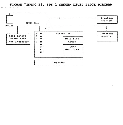
The Adaptec SDS-I (SCSI Development System) is a stand-alone computer system designed to fulfill a number of test needs for
SCSI peripheral development and qualification. Figure
INTRO-FI shows a system level block diagram of the SDS-I which includes a hard disk-based computer with graphics monitor, graphics printer (optional), and mouse interface.
FIGURE -INTRO-FI. SDS-I SYSTEM LEVEL BLOCK DIAGRAM
SCSI BlIs
S H C a
I Under Test S r
I
(Ylot i YIC lllded)I
d w a r eSystem CPU
Real Time Clock
20MB Hard Disk
Keyboard
Graphics Printer
I
v
[image:12.612.103.535.292.732.2]-INTRO.2 SDS-I PRODUCT DESIGN GOALS
The SDS-I was designed to perform in the following SCSI development environments for SCSI OEMs and System Integrators:
- Initial Engineering Debug:
During initial product debug, the development Engineer needs a versatile but simple tool to use. The SDS-l Development System's Menu Interface provides a quick, user-friendly testing capability at the SCSI electrical, message, command, status and sense levels.
- Final Product Debug:
The time-consuming final steps in product debug require tools which provide flexibility and power to czeate unique tests which can uncover the "hard-to-find" bugs. The SDS-I addresses this type of testing within the Menu Interface via a versatile menu-driven test
compiler. This feature allows the user to quickly
generate simple test sequences which can be executed with a single keystroke. The ultimate in flexibility can be obtained via use of the SDS-I's full Microsoft "C" compiler in the Stand-Alone Test (SAT).
- Engineering Performance Testing:
Fully documented Engineering Performance tests can be quickly generated via the SDS-I's Menu Interface or SAT utilizing the built-in documentation functions.
- Design Verification/Regression Testing:
The SDS-I provides a systematic approach to a "hands-off" initial design verification and regression testing during the course of the product's life. The Adaptec "Matched Set" (Test Procedure and Test Resul ts Report) Documentation- system provides the user with an easy-to-generate Test Procedure and Test Results Report which tracks the test procedure at a section, subsection, paragraph and subparagraph level.
- Product Assurance:
493119-99
With its ability to read and compare data up to 1.8 MB/second, the SCSI Development System allows Product Assurance a quick means of obtaining data reliability information. And with its Menu Interface, the SDS-I provides a user-friendly interface with versatility.
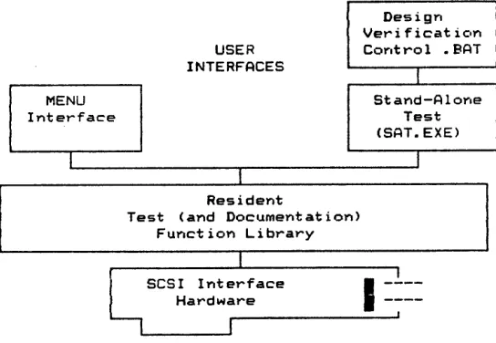
-INTRO.3 SDS-l DEVELOPMENT SYSTEM PRODUCT FEATURES
The power and flexibility of the SDS-l is provided by a three-level architectural approach (Figure INTRO-F2): SCSI Interface, Resident Test/Documentation Function Library (RTFL) and User Interfaces. The two user interfaces, MENU and SAT (Stand-Alone Test), provide the user with different levels of flexibility and complexity.
FIGURE -INTRO-F2. SDS-l ARCHITECTURE
Design Veri ficat icon
USER COYltrol • BAT
INTERFACES
I
MENU Stand-AloYle
Interface Test
(SAT.EXE)
I I
I
Resident
Test (and Documentation> Function Library
I
~SCSI Interface
I
-.!.--Hardware
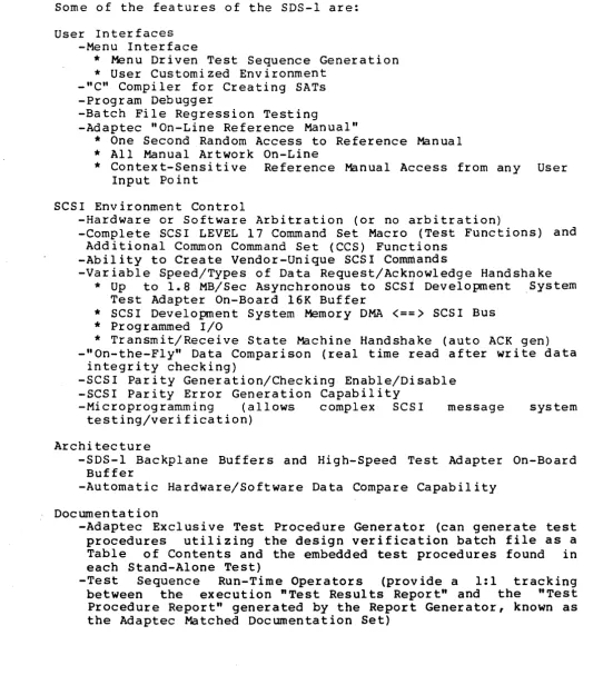
[image:14.612.183.455.220.408.2]Some of the features of the SDS-l are:
User Interfaces -Menu Interface
*
Menu Driven Test Sequence Generation*
User Customized Environment _"C" Compiler for Creating SATs -Program Debugger-Batch File Regression Testing
-Adaptec "On-Line Reference Manual"
*
One Second Random Access to Reference Manual*
All Manual Artwork On-Line*
Context-Sensitive Reference Manual Access from any User Input PointSCSI Environment Control
-Hardware or Software Arbitration (or no arbitration)
-Complete SCSI LEVEL 17 Command Set Macro (Test Functions) and Additional Common Command Set (CCS) Functions
-Ability to Create Vendor-Unique SCSI Commands
-Variable Speed/Types of Data Request/Acknowledge Handshake
*
Up to 1.8MB/Sec Asynchronous toscsi
Development ,SystemTest Adapter On-Board 16K Buffer
*
SCSI Development System Memory DMA<==)
SCSI Bus*
Programmed I/O*
Transmit/Receive State Machine Handshake (auto ACK gen) -"On-the-Fly" Data Comparison (real time read after write dataintegrity checking)
-SCSI Parity Generation/Checking Enable/Disable -SCSI Parity Error Generation Capability
-Microprogramming (allows complex SCSI message system
testing/verification)
Architecture
-SDS-l Backplane Buffers and High-Speed Test Adapter On-Board Buffer
-Automatic Hardware/Software Data Compare Capability
Documentation
-Adaptec Exclusive Test Procedure Generator (can generate test procedures utilizing the design verification batch file as a Table of Contents and the embedded test procedures found in each Stand-Alone Test)
-Test Sequence Run-Time Operators (provide a 1:1 tracking between the execution "Test Results Report" and the "Test Procedure Report" generated by the Report Generator, known as the Adaptec Matched Documentation Set)
[image:15.615.43.576.87.694.2]-INTRO.4 SYSTEM COMPONENTS
The SDS-I is comprised of the following hardware, software and manual components:
HARDWARE CONTENTS
- SDS-I
640K User Ram
One 360K Floppy Drive One 20MB Winchester Drive Real-Time Clock
One Serial Port One Parallel Port
One SCSI Single or Differential Test Port 80-Column x 25-Line Monochrome Display
- 80-Column Graphics Printer (Optional) Desktop Printer Stand
Printer Cable
- Mouse and Mouse Pad
SOFTWARE/ MANUALS CONTENTS
- SCSI Development System Software
"On-Line Reference Manual" .
Resident Test/Documentation Function Li~rary (RTFL) Run-Time Batch File Documentation Functions
Menu Interface
"C" Stand-Alone Test Generation Routines Test Procedure Report Generator
SAT/Regression Test Examples Interactive Editor
- SCSI Development System Reference Manual (Hard Copy) - SAT Library Catalog Binder
- Microsoft
"c"
Compiler Diskettes and Refe·rence Manual Set - PC DOS Diskettes and Reference Manual Set- Mouse Systems PC PAINT PLUS Diskette and Reference Manual Set - Computer Reference Manuals
-INTRO.S USING THE SDS-l
At this point, the user may be reading a magnetic version of the SDS-l Reference Manual, which is displayed at system boot time, or the hard copy version. The following steps will get the user involved with the SDS-l and serve as a quick system checkout.
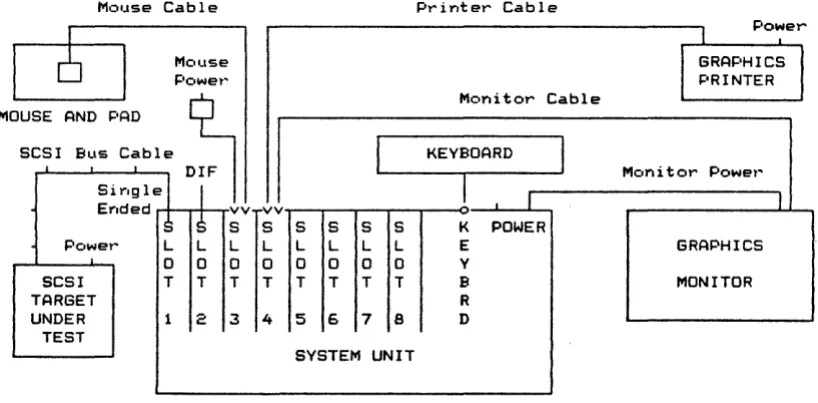
1. SYSTEM SETUP:
The system components (base unit, monitor and keyboard) should be connected as shown in Figure INTRO-F3. The printer
should be connected and on-line. .For customers
purchasing the SDS-l without a printer, connect one of the following qualified printers:
OKIDATA Microline 192 IBM Graphics Printer
The mouse should also be connected (refer to Section RPTG.2.l.2.S.l. for mouse hardware setup).
FIGURE -INTRO-F3. SYSTEM HOOKUP
Mouse Cable
.
MOUSE AND I=AD
SCSI BLls Cable
I
Sirlgle Erlded
:)
Power L
0
SCSI T
TARGET
UNDER 1
TEST Mouse Powet~ DIF I
S
L 0 T 2I
vvr
S S S S S S
L L L L L L
0 0 0 0 0 0
T T T T T T
3 4 5 6 7 8
SYSTEM UNIT
2. SCSI PERIPHERAL HOOKUP:
Printer Cable
Monitor Cable
KEYBOARD
I
I
1 IK POWER E
Y B R
D
Mon i t or Power'
I
GRAPHICS
MONITOR
Next, connect an SCSI peripheral disk or tape drive. If using a disk, try to choose a preformatted one. Pin One of the SCSI cable points up. It would be easier to run the example if the initial peripheral requires SCSI bus parity.
3. MENU INTERFACE:
It is now time to leave the "On-Line Reference Manual" and proceed to the Menu Interface. But before leaving the Help System, scroll the display such that the top line displayed
[image:17.613.137.546.344.545.2]is 3a. WRITING AND READING:. Now mark this line with Book Mark I by pressing ALT-l keys (while pressing the ALT key, press the 1 or number one key).
NOTE: This allows the user to reenter the Reference Manual (Help System) at this paragraph from the DOS command line by: C)SDSHELP BMI or from the reference manual TOC via the BOOK MARK SECTION and BMI.
If a hard copy of the Reference Manual is not available, the user may want to print out Step 3a: adjust the screen to Step 3a and press SHIFT-PrtSC. The user may want to do another print screen since this Step does not fit on a single screen.
To leave the Reference Manual (Help System), enter the ALT-H keys (while pressing the ALT key, press the H key).
3a.WRITING AND READING:
After leaving the Reference Manual, invoke MENU by entering:
C)MENU SAMPLES
at the DOS prompt. SAMPLES will initialize the system and place the user in the RANDOM menu. If the initial peripheral does not require parity, th~ user may reset parity(I) in the
SETUP Menu to parity(9) (refer to MENU.I.I). To get
acquainted with the SDS-l MENU, perform the following
operations:
KEYBOARD INPUT FOR DISK FOR TAPE
R S
T T
N N
W W
E B Z
F
X A B
Z F
DESCRIPTION
If Already in Proper Menu, Skip Performs SCSI Bus Reset
Per forms Sense Command Write 10 Blocks
Rewind Tape Reads 10 Blocks Move to BUFFER Menu Displays Read Buffer Displays SCSI State Log
Return to the Reference Manual by pressing the ALT-H keys. The user will return to the Reference Manual at MENU.3 BOFFER MENU. Return to Step 3a by pressing the 1 (number one) key for Book Mark 1.
NOTE: If the user has followed Step 3a, the Reference
Manual (Help System) was entered through MENU. To
return back to MENU, enter ALT-H.
4. SDS-1 ARCHITECTURE BASICS:
proceeding, a few architectural concepts should be understood.
INTRO.S.l SDS-I ARCHITECTURAL CONCEPTS
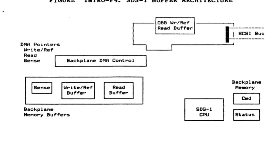
INTRO.S.l.l BUFFERS
Figure INTRO-F4 shows the basic buffer structure of the SDS-l. Initially, we will focus on the backplane memory buffers: Write/Reference, Read and Sense. All SCSI DATA OUT transfers are taken from the SDS-l write buffer. The starting location of the transfer is set by the Wr i te DMA po inter. The SDS-l prov ides a number of different buffer fill functions which allow the user to create any data pattern in the write buffer. Unless changed by the user, the write/reference buffer is the target buffer for all fill functions.
With the exception of the sense() command, all SCSI DATA IN transfers write data into the SDS-l read buffer. The starting location of the transfer is determined by the Read DMA pointer.
The sense buffer is dedicated to SCSI sense DATA IN. Each sense() command writes data into this buffer starting at DMA address 0.
The SDS-l manages buffer wraparound for the backplane buffers. This means that if a transfer exceeds the size of the buffer, the SDS-l will automatically stop the transfer at the buffer limit, reset the correct DMA pointer to the start of the buffer, and continue the transfer.
FIGURE -INTRO-F4. SDS-l BUFFER ARCHITECTURE
DMA Pointers Write/Ref Read
1
0BB Wr/Ref
l
Readr--Bu __ ffe __ r _________[~---
I SCSI Bus---
, ' - - - 'Sense Backplane DMA Control
Backplane
M~mory Buffers
493119-99
Backplane Memory
r-:::I
COld~
Istatus [image:19.613.86.536.450.689.2]The SDS-l provides numerous transfer modes: Programmed I/O (PIa), Transmit/Receive (TR), Direct Backplane Memory Access (DMA) and High-Speed Direct Memory Access to the SDS-l On-Board Buffer (HS). In addition, various methods of data comparison can
be specified. The following section describes the most
commonly used method, Hardware Compare.
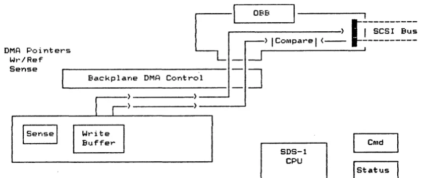
INTRO.S.l.2 HARDWARE COMPARE
When operating in a hardware compare mode, the SDS-l transfers SCSI DATA OUT information from the WRITE/reference buffer (see Figure INTRO-FS) using the DMA poInter. During SCSI DATA IN phases (with the exception of a sense() command), the SCSI bus data is held on the SCSI bus and compared against the write/ref buffer (via a hardware comparator) using the Write DMA pointer as an index into the write/REFERENCE buffer. Since data is read from the write/REFERENCE buffer via DMA, this is a very fast operation.
FIGURE -INTRO-F5. SDS-l HARDWARE COMPARE
DMA P,::oi nters
Wt~/Ref
Cr
t OBB
I
J!--- J!--- J!--- J!--- J!--- J!--- J!--- J!--- J!--- , ) I SCSI Bus
) I Compare I ( - -
~---.I
Sense
~
___ Ba_c_k_p_l_a_ne_D_M_A_C_o_n_t_r_O_l ___==
~
~
~
Cnld
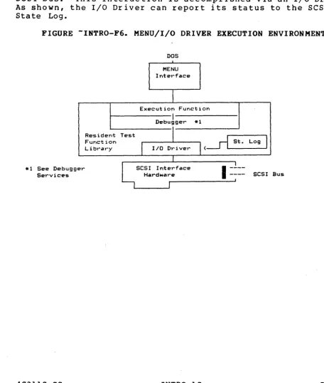
[image:20.613.116.537.337.513.2]INTRO.S.l.3 I/O DRIVER/MENU EXECUTION ENVIRONMENT
Another concept to understand is the Menu Interface/I/O Driver execution environment and its relationship to the Resident Test
Function Library (RTFL). Figure INTRO-F6 shows the basic
architecture of the SDS-l. The Menu Interface is a special application designed to give the user easy access to the SDS-l Resident Test Function Library. This library lives in system memory, just like DOS and is accessible via a fixed entry point. The Menu Interface simply allows the user to make function calls to the library in the order chosen. Certain functions within the function library (such as writer() or readr(» interact with the SCSI bus. This interaction is accomplished via an I/O Driver. As shown, the I/O Driver can report its status to the SCSI Bus State Log.
FIGURE -INTRO-F6. MENU/I/O DRIVER EXECUTION ENVIRONMENT
*1 See Debugg Services
403110-00 er
Resider-It Fur-Ict ion
L i bt~a.t~y
DOS
MENU Interface
i
Execution Function
I
Debugger *1
Test
'(
<~
St. LogI
I
I/O DriverI
~SCSI Interface
I
-~--Hardware ---- SCSI
I J
Bus
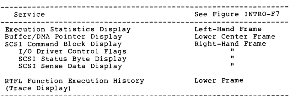
[image:21.620.65.522.235.773.2]The Resident Test Function Library by t he S D S -1 ' s Me n u l n t e r fa c e. following services to the MENU:
Debugger is heavily utilized The Debugger provides the
Service See Figure INTRO-F7
Execution Statistics Display Buffer/DMA Pointer Display SCSI Command Block Display
Left-Hand Frame Lower Center Frame Right-Hand Frame I/O Driver Control Flags
SCSI Status Byte Display SCSI Sense Data Display
RTFL Function Execution History (Trace Display)
"
"
"
Lower Frame
In addition to the display services, the RTFL Debugger also provides a Debugger to aid in the debug of MENU Function Key
(FKEY) sequences or Stand-Alone Tests.
FIGURE -INTRO-F7. RTFL DEBUGGER DISPLAY
110 DRIVER STATUS
110 ops: 2F ucO: 110 C.;:.rnmar,d Parameters stat: 00
TGT Chks: 0 ucl: CDB: 08 00 00 cO 40 00 sense: (old)
INT D Er: 0 00 00 00 00 00 00 00 00 00
Bytes Wr: F0400 Wr/Ref: BPM )(fer: OMAHC a.s. :OFF
Bytes Rd: SOOOO 0000 s. 1. ON arb. HOW sel.SMA
Bytes Cp: 20000 Rd Buf: b.p.OFF b.w.OFF
Crnp Ers. : 0 ha: 0 iid: 7 tid: 4
TRACE ISPLAY
writer(OS80,40) overbcw(05cO, 0100, 0000, 4000) writer(05cO,40)
overbcw(0600, 0100, 0000, 4000) writer(0600,40) overbcw(0640, 0100,0000, 4(00) writer(0640,40) overbcw(0680, 0100,0000, 4000) writer(0680,40)
overbcw(06cO,0100, 0000,4(00) writer(06cO, 40) paragph() ackdelay(2100) fi11pr(009f, 0000, 0200) savebuf(OBBIMG. TST, 0000, 0200) writer(OaOO,2) paragph() dmarst(R) ackdelay(O) readr(OOOO, 0(40) paragph() dmarst(R) ackdelay(lS) readr(0040, 0(40) paragph() dmarst(R) ackdelay(255)
readr(0080, 0040) paragph() dmarst(R) readr(OOCO,0040) paragph() dmarst(R)
readt~(0300,001F) readrC031F,(020) readr(033F,0001) paragph() ackdelay(O)
dmarst(R) readr(0900,000l) readr(0901,0010) readr(0911,OOOF)
00
[image:22.612.96.558.124.277.2]This concludes the basic SDS-l architectural concepts. The following outline is provided in order to guide the user through the use of the SDS-l Menu System into Stand-Alone Test Generation and onto SCSI Design Verification Testing.
TOPIC
MENU System
Individual Menus Parameter Save/Load FKEYs
Saving/Loading Debugging
Host Emulation (I/O Driver operation)
SAT Generation
I/O Driver Environment Debugger
State Log
Microprogramming Function Library
Design Verification
Report Generator
-INTRO.6 HELP SYSTEM
REFERENCE MANUAL SECTION/SUBSECTION
Menu Inter face
M:n u Inter face/ "menu name" Menu Interface/Other/Exit M:nu Interface/FKEY Menu
"
"
I/O DriverStand-Alone Test I/O Driver
Debugger State Log
Microprogramming Function Library Appendix A
Design Verification
Design Verification Report Generator
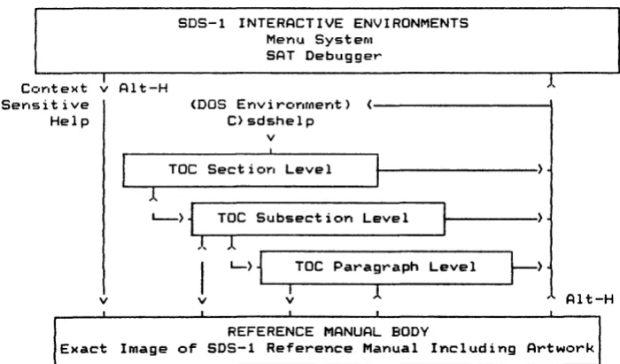
The SDS-l Help System provides two features to the user. First, the Help System contains the full SDS-1 Reference Manual (including artwork) with an electronic Table of Contents (TOC) which can access any page in less than a second. The other feature is that the Help System is integrated with the SDS-l Menu Interface and SDS-1 Debugger to provide the user with "context-sensitive help" at any user input point. That is, whenever the SDS-1 requires a user input, the user can press ALT-H keys to
get more information from the Reference Manual.
Figure INTRO-F8 shows a diagram of the Help System starting with the two methods of entry, context-sensitive (ALT-H) or direct entry (DOS environment). To utilize the direct entry feature of the SDS-l Help System, the user enters "SDSHELP xxxxxxxx" at the DOS prompt, where "xxxxxxxx" is the reference manual entry point. Below are some examples:
C>SDSHELP writer C>SDSHELP INTRO.5 C>SDSHELP
The first command will take the user to the writer() function description page in Appendix A. The second command will take the user to Section INTRO.5 and the last command will take the user to the Electronic Table of Contents (TOC). The electronic TOC is the default if the reference manual entry point is not found.
FIGURE -INTRO-Fa. SDS-l HELP SYSTEM
SDS-l INTERACTIVE ENVIRONMENTS Menu System
SAT Debugger
Context ~ Alt-H 1
Serlsit ive <DOS Envirc'Ylfoerlt) ( - - - \
Help C}sdshelp
v
Toe Section Level 1
L->1~~T~O_C
__ S_ub_s_e_c_t_i_o_n_L_e_v_e_l __~---,I. 1
I
L-) 1L----r_T_o_c_p_a_r_a...,g_r_a_Ph_L_e_v_e_l __...I~)
I 1
v v
v
REFERENCE MANUAL BODY
Alt-H
Exact Image or SDS-l Reference Manual Including Artwork
Once in the Reference Manual Text, the user can move from one end of the manual to the other. The three-level TOC provides top-down access to all SDS-l subjects.
[image:24.613.143.493.311.516.2]Below is a l i s t of commands used in the magnetic version of the Reference Manual:
IN THE TOC BODY
Select Section, Subsection or Paragraph: Expand Section, Subsection or Paragraph: Contract Subsection or Paragraph:
Swap to Original Screen (before Help): Exit Help Screen:
IN THE REFERENCE MANUAL TEXT BODY Scan through Text:
Return to TOe: Set Bookmarker: Go to Bookmarker:
Swap to Original Screen (before Help): Exit Help System:
403110-00 INTRO-14
KEYS TO USE: Up or Down Arrow Carriage Return ESC
Space Bar ALT-H
Up or Down Arrow or Page Up or Down ESC
ALT-0 through ALT-9
o
through 9 Space Bar ALT-H-MENU. 9 MENU INTERFACE
-MENU.l INTRODUCTION/OVERVIEW
The Menu Interface allows execution of the Test/Documentation Functions via an interactive menu-driven system. It supports both the I/O Driver and Microprogramming execution environments as shown in Figure MENU-Fl.
FIGURE -MENU-Fl. MENU INTERFACE EXECUTION ENVIRONMENTS
f i l l i ( ) f i l l d ( )
WRITE BUFFER READ BUFFER
I/O DRIVER
Data Compare Funct ioY.
"',n'~ iter () USE R GEN • . .
-readr () I/O sense() COMMAND
xferm.:.de () arbm.:.de () ' - - - ' se 1 mode ( )
f i l l i ( ) I WRITE f i lld () BUFFER dmaset() .... _ _ _ _ ..J
cornpwr()I READ drnaset() _ BUFFER
busywai t () exp_status()
i id ( )
tid ()
USER
MICRO-PROGRAMMING
FUNCTION
arb() sell () c:db61 () datainO stat in () msgin ()
~---.) OPTIONAL SCSI
bus_logen() BUS STATE
< - - )
l
::::Wr-I
A_R_E _ _I. __
~I__ ~~~
I parityOThere are currently eight menu displays or screens (SETUP, BUFFER, RANDOM, SEQUENTIAL, I/O DRIVER, MP, FKEY and OTHER/EXIT), each of which contains a set of functions that can be executed
with a single keystroke. In addition to executing these
functions, there is the ability to edit individual function parameter(s). The Menu Interface also has the flexibility to custom-build function sequences that can be executed by a single keystroke (FI through FI0). The function key (FKEY) sequences' are discussed in more detail in section MENU.S •
The Menu Interface is invoked by the command:
C)MENO <filename)
where the file name is optional. The file name is the name of a file that has the stored parameter value set which had been saved from a previous Menu Interface session. If the file name was not specified, default parameter values will appear on the menu screens.
Once the menu initialization process is done, one of the menu screens will be displayed. This is the default screen which can be modified by the init menu function in the OTHER/EXIT menu. To display the other menu screens, use the Left or Right Arrow keys or the menu code which is highlighted on the Menu Page Select Line displayed at the bottom of the screen. The current menu screen is noted in inverse video.
The Menu Interface screen contains three major areas: Debugger Window, Menu Screen and Trace Display. The top portion of the screen is the Debugger Window which provides the user with information such as statistics, counters, buffers, SCSI command bytes, sense display and other status. The Debugger Window is discussed in more detail in the DEBUG.2.1.3 section. The lower portion of the screen is the Menu Screen which displays the current menu with its functions available for execution. The Trace Display is swapped with the Menu Screen; i t shows the execution history of the Test/Documentation Functions that have been executed (refer to DEBUG.2.l.4).
-MENU.l.l PARAMETER SETUP IN THE EDIT MODE
The edit mode is used-to set up or modify parameter values. To enter this mode, hold down the CTRL key while pressing E (will be written as CTRL-E or AE) at the menu screen. To exit this mode, enter A E again.
While in the edit mode, the cursor will appear in the current parameter field which is displayed in inverse video. A help reference line with a brief description of the current field will also appear at the bottom of the screen. To move the current parameter field to the previous or next field, use the Up and Down Arrow or Return keys. The Home key will move the current parameter field to the first parameter field at the top of the menu screen and the End key will move i t to the last function.
The PgOp and PgDn keys will move up or down a line to the first parameter field in the line. A summary of the edit mode keys are displayed at the bottom of the screen.
To edit the parameter value, type in the new value in the parameter field. The values maybe in decimal, hexadecimal or alphanumeric. Some parameters are strings which are noted by double quotes. If the value is to be hexadecimal, an "x" or "X" must appear in the field before the value. For example, decimal 256 is 0x100 in hex, the "X" must be present so that the Menu Interface will interpret this value as a hex value. There is some range and type checking, so that an error will appear if the value is not within its limits or if i t is an illegal value. This error will continue to show until a legal value is entered. The displayed value in the parameter field is the value to be interpreted by MENU, so be sure the correct value is shown.
Some of the parameters are toggles. To modify these values use the Left or Right Arrow keys. Refer to the bottom of the screen for other instructions on editing parameters.
-MENU.l.2 FUNCTION EXECUTION
When parameters have been setup, the user may execute these functions. If the user is in the edit mode, be sure to exit that mode. On the menu screen, each function has a highlighted or intensified character preceding the function name. This is the execution key code associated with the function. When this key
is entered, the function will execute using the displayed
parameter value(s). Only functions in the current menu can be executed.
Some execution key codes are shown in inverse video. These
functions are toggles. Their purpose is to set flags or
variables. They are not part of the Test/Documentation Function Library.
MENU.l.3 TRACE DISPLAY
When executing a Test/Documentation Library function, the menu display is replaced by the trace display which shows the function name and parameter(s) that have been executed. Internal Menu functions (functions that are not part of the Test/Documentation Library) do not appear in the trace display.
When in the menu display, the trace display can be viewed by pressing the Space Bar. Pressing the Space Bar again will return the user back to the menu display.
MENU.l.4 SETTING ERROR ACTION
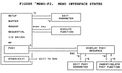
MENU.l.S MENU INTERFACE STATES
Figure MENU-F2 is a diagram of the Menu Interface states which display the various states and modes that can be accessed through
the different menus.
FIGURE -MENU-F2. MENU INTERFACE STATES
AE
j
SETUP EDIT
PARAMETER BUFFER
RANDOM exec key
) 1
EXECUTESEQUENTIAL FUNCTION
I/O DRIVER
MP
FKEY
~:
DISPLAY FKEYSEQUENCE
I
ESC... A
OTHER/EXIT
~)
EXIT TO DOS vEDIT FKEY PARAMETER
-MENU.2 SETUP MENU
The SETUP menu contains functions that control the execution environment of SCSI execution functions. A typical SETUP menu screen is shown on the next page.
[image:29.620.114.532.141.392.2]FIGURE -MENU-F3. SETUP MENU SCREEN
lID DRIVER STATUS
lID Ops: 0 ue!): 1/0 Command Parameters stat:
TGT Chks: 0 ue1: COB:
-- --
-- --
--
--
sense:INT 0 Er: 0
--
---- --
--
--Bytes Wr:
°
Wr/Ref: BPM )(fer: DMARW a. s. :OFFBytes Rd:
°
0000 s. 1. ON arb. HOW sel.SMABytes Cp: 0 Rd Buf: BPM b.p.ON b.w.OFF
Cmp Ers. : 0 0000 ha: 0 iid: 7 tid: 4
~OS-l MENU (Jun 12 19 6 FC=4) SETUP FUNCTIONS
Z:exeeute_all(l);
X:xfermode(IIDMARW ",Ox40(0);
I: iea ("LOGC") ; 5: line_mode ("S") ;
7: i ot 0 ( 30) i
F:arbmode(IIHOW II); J:selmode(ISMART")i Y:parity(1) ;
Q:tid( 4);
D: i i d ( 00, 07) ; L:lurl( 0); 1 :ent lbyte ( (0); A:stats_reset(IIA II);
E:eea(IILOGC");
V: f i )( ed ( 1 ) ;
N:autosense(O); W:busywait(O); G:bus_logen(1) ; 2:aekdelay( 0000);
C: bCIJ (1) ;
3: statsen (1) ;
4:stats_window("G");
P:fillbyte(O)(SA, OOOO,OxFFFF);
SETUP BUFFER RANDOM SEQUENTIAL I/O DRIVER MP FKEY OTHERIEXIT Select Menu: <,>,U,B, ••• Edit Parms:AE Function Exec:Z,X,7,F, ••• Help:ALT-H
While in the edit mode, reference information or help on any of these functions can be accessed by moving the cursor to a parameter in the desired function and holding down the ALT key
and pressing H (will be written as ALT-H). All
Test/Documentation Library functions can be accessed directly through the edit mode (as described) or through the Table of Contents in the Help System. There are some functions in the Menu Interface that are not part of the Test/Documentation Library. These functions are internal Menu Interface functions and they will be described throughout this chapter in their respecti ve places.
-MENU.2.1 EXECUTE ALL FUNCTION
In the SETUP menu, there is only one internal function called
execute all. This function will execute all of the SETUP
functions listed in the SETUP menu when enabled (parameter set to
1) •
In the menu initialization process, the execute all function is checked. If i t is enabled, all of the SETUP functions will be executed as part of the initialization. Otherwise, none of the SETUP functions are executed.
[image:30.612.109.552.112.326.2]-MENU.3 BUFFER MENU
The BUFFER menu contains buffer related functions such as the various fill functions that can create several different types of data patterns in the selected buffer. There are other functions that allow the user to display, load and save buffers, and alsq have the ability to reset or set the buffer pointers. A typical BUFFER menu screen is shown below.
110 Ops:
TGT Chks: INT 0 Et~ : Bytes Wr: Bytes Rd: Bytes Cp: Cmp Ers. :
FIGURE -MENU-F4. BUFFER MENU SCREEN
°
°
°
°
0
°
°
ucO: uc1:
I/O DRIVER STATUS
I/O COMmand Parameters CDB:
Wr/Ref: BPM xfer: DMARW a.s. :OFF
0000 s.l.ON arb.HOW sel.SMA
Rd Buf: BPM b.p.ON b.w.OFF
0000 ha:
°
iid: 7 tid: 4stat: sense:
SDS-l MENU CJurl 12 1981 FC=4) BUFFER