""DDC
jjAPR 19 1974
CONVERSION OF THE D37C COMPUTER FOR
C
Ora GENERAL PURPOSE APPLICATIONSTHESIS
GE/EE/74-16 Dennis C. Reguli
2Lt.
USAF
....-.... ... " rj • r iP~led
Reproduced by
NATIONAL TECHNICAL
INFORMATION SERVICE
U S lepartment of Commerce Springfield VA 22151
Unclassified
SECURITY CLASSIFICATION OF THIS PAGE (When Dare Enteted)
REPORT DOCUMENTATION PAGE NS BFREAD EFORE COMPLET'ING FORMSLETRUCWOFS
1. R6PORT NUMBER 2. GOVT ACCESSION NO 3. RECIPIENT°S CATALOG NUMBER
GE/EE/?4-!61
I
4. T!TLE (end Subtitle) S. TYPE OF REPORT & PERIOD COVEPED
CONVERSION OF THE D37C COMPUTER MS Thesis
FOR GENERAL PURPOSE APPLICATIONS 6. PERFORING ORG. REPORT NUMBER
7. AUTHOR.as) 3. CONTRACT OR GRANT NUMSER(s)
Dennis C. Reguli
aLt.
USAF9. PERFORMING ORGANIZATION NAME AND ADDRESS 10. PROGRAM ELEMENT. PROJZCT. TASK
Air Force institute of Technology (AFIT- AREA • WORK UNIT NUMBERS
EN) Wright-Patterson AFB, Ohio 45433
11. CONTROLLING OFFICE 4AIPE AMI ADDRESS 12. REPORT DATE
March, 1974
43L NUMBER OF PAGES
168
14. MONITOFNG AGENCY NAME & ADDRESS(Ui13fiae2. rom Co-trolflin Office) 15. SECURITY CLASS. (of this repon)
1
4mIS OECLAS5IFCATION/DOW'IGRADIHG
SCHEDULE
IC DISTRIBUTION STTEMENT "'ot this Report)
Approved for public release; distribution unli.ited
17. DISTRIBUTION STATEMENT (of the &b*t&ac1 entered in Block 20. P' different from Rteport)
I&. SUPPLEMENTARY NOTES
Ap ved for 9 ublic releases IAW AFR 190-17
Kt. WORDS r am.. on r0~e46e aid& if n&eeAfy end lde!i.'y by black uism.l t)
Minuteman II Computer D37C Computer
Minicomputer, gencral purpose
20. AISTRACT (Ctnhw.•an revers side It neceita.y arW Identify by bock mei)
" Thio report addresses the problem of reutilizing later Minuteman
com|puters, D37C's, which will become surplus in the near future.
Revitilization is assumed optimum by first converting into a
general purpose minicsomp-ter. This is done for the D37C by
supplying external support systems, control and monitor circuits,
and expanded I/O capability. The external systems include power supplies and cooVing system and were provided at AFIT by
labora-III •
~~torygenerators and
r
fan and pump assembly, aespe~vlve
jý,
ct11 vil1 h
i J 1473 ITOrN oi m N soLET
Unclassified
* SE=V.I!TY CLASSIMIATION OF THIS PAGE(ft&3 Data Estosme
generators produce the 28vdc at 15 amp and the 22vrms, 400 Hz, 30 current reqliired by the computer and the cooling system provides less than continuous duty cycle cooling. The Control and Monitor circuits are required to control the mode transitions of the machine and to monitor the results. The simple circuits required were expanded to include a program load scheme using a multiplexed output, Mpx. The final Control and Monitor system will provide sufficient
I/O
capabilities for many applications, however, an expanded I/O system was developed for more versatili-ty. The expanded I/O system providas for program controlled I/O, a parallel data bus for an I/O port, and a speed increase of 50 words per second to 100 plus.I - O . S Dat
-.. ,. . .' -. - f.-. : •.
•..--m
;.. . . . . .. ... .- ."
- . ; :V " • • -.;: 5 .
'.-• S-s " -- n la f
D
--AL 9) 1974
C
CONVERSION OF THE D37C COMPUTER FORC
GENERAL PURPOSE APPLICATIONS
THESIS
GE/EE/7I4-16 Dennis C. Reguli
MLt. USAF
""
:
:19!
I
III
Reomdoced by
NATIONAL TECHNICAL
INFORMATION SERVICE
USDpartmen ef COn D-C Sprftsagfd VA 22151
CApproved
for public release# distribution unlimited.b
I
"CONVERSION OF THE D37C COMPUTER FOR GENERAL PURPOSE APPLICATIONS
THESIS
Presented to the Faculty of the School of Engineering
of the Air Force Institute of Technology Air University
in Partial Fulfillment of the
Requirements for the Degree of
"Master of Science
by
Dennis C. Reguli, B.S.E.E.
2Lt.
usAF
Graduate Electrical Engineering
March 1974
GE/AE/74--6
(_
PrefaceIn this report I have tried to show that a Minuteman guidance and control computer, the D37C, can be converted for general purpose applications through the addition of a few simple circuits and systems. I .oe my efforts will assist the Air Force in reutilizing these machines in laboratories or at least, I expect my work to be the foundation for fur-ther study in reutilizing these machines by civilian
institu-tions. S~/
* This investigation considers only hardware system6 added
to the machine and does not include software develay nt tor
machine modifications. In short, any graduate or advaz.c-d
(•
Cundergraduate student in Electrical Engineering may use my
work and a bare D37C 4.omputer to produce a versatile, general
purpose minicomputer. The essential elements for this
con-versinn are inclt,4;d in theý circuit descriptions and
schema-tics of •dF!es B and C.
I
wiz
to acknowledge my i...nbtedness to several
indivi-duals .; the prepe.ation c< -•,.a report.
I thank Messrs.
Welli,
Fisher, and KuciLenbeczer for their technical assistance
through telephone interview.
Thanks also goes to Prof. Lamont,
$
my thesis advisor, for his motivational force and patience with
broken deadlines.
Messrs. Wolfe, Short,
and
Bayard were of
great assistance in constructing some portions of the console,
I an deeply indepted to lab partners Lt.9s Lundy and Kennedy
Final-I GE/'EE/?4-,26
lys I wish to express sincere thanks to my wife who helped in proof reading and persisted through weekends and evenings of neglect.
GE/E-E/74-16'
S(
ContentsPage
Preface . . . . . . . . . . . . . . . , . . * . . , ii
List of
Figures.
,
. . . . .
.*.
. . .
.a
* * e s* viiList of Tables . , * . . a a a a . . * . . . a a . ix
Abstract e * 6 a * • • * P * * * * a * e . o * * * * x
I. Introductior .. . . .. . . . .a . . . . * . 1
Backgrounds oa
References aaaaaaaaaaaa a * 3
Problem Statement. . . . . 4. 4
Problems a . * a * a a*e a 4
Constiraints * * a * a a * * e a 5 Method of Attack * . a .. ... . 6
Basic D37C Computer Description * a * . . • . 6
D17B Comparison . . . . . . • • 7
D37C Characteristics . .. aa . . . 7
"Scope and Organization * . . .
10
Scope * a * a * e % * . a a . a
10
Conventions 0 a . 0 0 * . •11
Structure o • a a * a a a e a a a a a • 12
II. External Support Systems... • 13
Power Supplies s.. . 13
Specification o.n. ... . a 13
Organization . . 15
Design e a a ! 6
"Realization * a a a 3 a 17
Cooling System . . .. ... .* 19
Specifications a . . 19
Organization .21
Design * & a 22
Realizaticn . 22
Conclusion . a . . a a a . a a a 0 . . . a 24
summary
& . . 0 0 a * . . . . . a24'
System Interconnection 9. a* * •* * e * . 25
Recommendations , * • • e * a * * * e * * 25
III. Control and Monitor Systems . . . . * a * * * e 28 Interfacing . ..
&.
**.. . . . 28Mode Con trolland dMonittr *.0 ... 0 29
Major Modes , a•• •• •• 29
Specifications and Organization a • 31
Design and Realization.. a . . a a a 37
GEAE/74-16
(
1ContentsPage
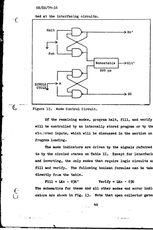
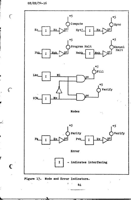
Program Loading 42
Specific: ion and
Organization
. 42Design
and Realization.44
Register Display.. Specification and Organization 0 . . . .. 45
a 48
Design * e e s e • * • • e 50
Realization a 51
Conclusions •.• ••.• .•.•60 * IV. Input/Output Expansio icn. . . 61
Specif ications.... . . . . 62
Programmed!/0. *. .* e e 62
Parallel Data Bus . . . . .. .. 62
Speed Increase .. . • • • • 63
Organization. ... . ... • 64
Hardware Resources.. . .. * 64
Software Conventions * •• 65
Design. a . . . .. . 68
Input . . . . . * 68
Output. a a . . * • 0 * a a 0 69
Control • a a • • • • a • * 71
Realization eaa aa. *aaea..a 71
Input . e 72
output a a 73
Control a a a a a a a a • 73 Peripheral Interface Specifications . . . . 76
Software e a a a e a a a a a a * a a 76
Conclusion . a a a a a a a a a a a a a a a a 78
V. Sumnary a a a a 0 a • a a a a a • a a . 0 80 Final System Description * a . . a a a . a . 80
Interconnections c . n . . . . 80
Physical Locations a a a a a . a a . a . 81
Conclusions. . . a a a . a . a a . a a a a 84
Power
andCooling
.8.4. . .. . a .8
Control and Monitor .e... .
84
I/0 Expansion ,*. . • * e .s 85
Recommendations . . . * . • 85
Concluding Statement • a a a • a a a • • • 87
B ibltiography aaaaaaaaaaaaaaaaa aaa 88
Appendix As D37C Computer Description a a a • a • a • 90
CAppendix
B: Available Computer Signals and InterfaceSche matics... 100
GE/EE/74-16
Contents
Page
Appendix Cs System Schematics . . . 140
Vita • • . • • • • • • • • £ 157
GE/EE/74-16
List of Figures
Figure Pae
1 Photograph of a D37C Computer. . . . . . . . 9
2 External Support Systems; Block Diagram . . . . 13
3 Specified Memory Power Wave Form . 0 # • . . 14
4 PDU Circuits • • * & • • • • • • • • . . . . . 18
5 Power Distribution Unit . . . .. .... ,.. 20
6 Computer Cooling System . . . .. ... 23
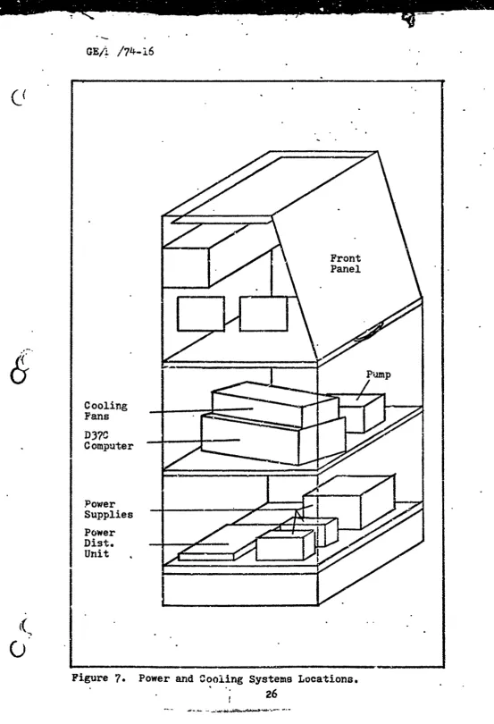
7 Power and Cooling Systems Locations . . . . . 26
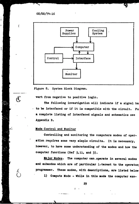
8 System Block Diagram • •• •• •• 29
9 Timing Sequences for Mode Control . . . . . . . 33
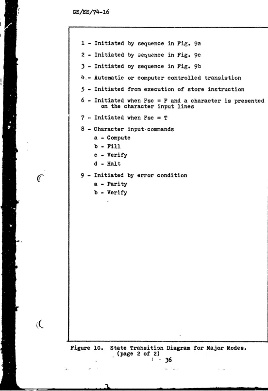
10 State Transition Diagram for Major Modes . . . 35
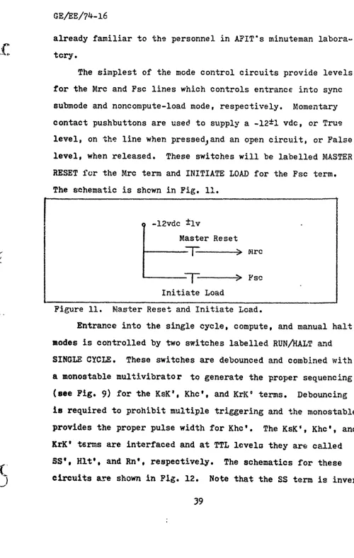
S11 Master Reset and Initiate Load • • • • • , • . 39
12 Mode Control Circuit . • • . • • . a * . * . . 40
13 Mode and Error Indicators .. , ,. , 41
14 Program Load Circuit • • • • • . . . . . . 46
15 Channel Display Select • • •... • • 49 16 Logical Flow Chart for Register Display . . ° , 52
17 Display Timing Diagram •.••..• ..•• * 53
18 System Clock Timing ... e. .e. . 54
19 Channel Display Select • o• ce . . . . 56
20 Register Display Circuit • •• ,• •• 57
21 Register Display Circuit • • • • • • • • . . • 58
22 Bank Monitor o * s * • £ • a o e • • • 58
23 System Clrck o•. a• .•e•• • • 59
S~24 Total D37C Sý,tem..,. 4 . .e , . 61L
GE/ER/74-16
IiFigure Page
26 Telemetry
Monitor
Timing . . . . . . . . . . .70
27 Example of Data Bus and Flag Bus Input . . . . 72
28 Output Schematic
74
29 Signal Distribution Unit • . • . . • • • . • . 77
30 System's Physical Locations . . . . . . . , . . 82
31 Console Front Panel. . .*. ... ... 83
.•32
Word Formats
* e
•
o e & o * * a @
• •
a 0
•
96
33 IW Parts Location . . . . . . . . . . . . . 125
6
33
Slamplectin...~.
1234
SampleReceiver
Circuit . .& a 6 a 0 a . 126 35 Sample Cable Receiver . . .0 . . . .0 . .0 . . 12936
12 Parts Location ... 13337 Sample Bus interfaces-. *.*** . *..
134
38 Sample Channel Driver.. * .... ... 136
339
Sample Control Interface • • 9 * # # .*
.•#
137
40 Miscellaneous Input Circuits and Connections * 13941
PDU
Circuits . 14242 Power Distribution Unit.. . . .Oa . . a . .0 143
43 Signal Distribution Unit a. 0. •. . .. & a. 144
414
PB Parts Location. . .. a . a . a . 0 . T . .145
45 Mode Control and Bank Indicators . . . . * . . 146
46
Program Load Schematic . . 0. a .. . . . .. aa .147
47 Register Display * o • • • *• 0 *0 • • 1 a a 149
48
Parts Locations for A... .. * 0 0 . . . 151 49 Mode Displays and IOP Driver * e *• . & . 15250 Channel Select * , & . . a • &, • a • a a •
153
(
51 System Clock Schematic . . .. .a
. . .154
"52
I/0
Output Schematic .155
viii.
GE/eE/74-16
f
Li.stof Tables
Table Page
I
Comparison of DIB and D37C . . . . . . . . . . 8II
Mode Monitor Signal States . . . . . . . . . . 38III Character Input Codes... . . . . . . 03
IV Bank Monitor Signal States . . . . .e. 50 V Model I/O Program Blocks ... . 67
VI D37C Computer Instructions . . . . . . . . . . 98
VII D37C Interface Signals 0 , d .0. . . .0. .. .* 103
VIII Signal Requirements for I/O Types ... * e • 117 Computer Cable Wiring List . . . . . . . . . 121
X Signal Receiver Circuits ... 126
XI Cable Interface Circuits ... , . . 129
XII Cable List fromll .. .. ... . 131
XIII Bus and Flag Interfacing .... . . 134
XIV Channel Select Circuits . . . ... 136
XV Control Signal Interface .. , .. • 137
XVI Cable List to 12 . . °. . ... 138
ix
GE/EE/74-16
Abstract
Since the Air Force surplused Minuteman guidance compu-ters there has been an interest in reutilization by civilian institutions. This report addresses the problem of reutiliz-ing later Minuteman computers, D37C's, which will become sur-plus in the near future. Revitilization is assumed optimum by first converting into a general purpose minicomputer. This
is done for the D37C by supplying external support systems, control and monitor Circuits, and expanded I/0 capability.
The external systems include power supplies and cooling system and were provided at AFIT by laboratory generators and a fan
and pump assembly, respectively. The generators produce the 28vdc at 15 amnp and the 22vems, 400 Hz, 3% current required by the computer and the cooling system provides less than con-tinuous duty cycle cooling. The Control and Monitor circuits are required to control the mode transitions of the machine and to mofnitor the results. The simple circuits required were expanded to include a program load scheme usLg the character inputs, and a register display output using a multiplexed out-put, Mpx. The final Control and Monitor system will provide
sufficient I/0 capabilities for many applications, however, an expanded
I/0
system was developed for more versatility. Theexpanded
I/O
system provides for program controlled I/O, a parallel data bus for anI/0
port, and a speed increase of 50 words per second to 100 plus. The converted D37C final system will provide many inutitutions with a highly reliablo andver-satile
minicomputer.GEA180/74-l6
1. Introduction
This Is a report on developing a process to convert the
Minuteman guidance and control computer, the D37C, into a
general purpose minicomputer, The introduction will discuss
previous work in the general area, state explicitly the
prob-lems uf eevelopient, describe the basic machine structure, and
provide some insight into the scope and organization of the
remaining report. This report assumes the reader has some
Electrical Engineering background and comprehends basic
digi-tal logic circuits and Boolean Algebra. It would also be
helpful, though not necessary, for the reader to be familiar
with basic computer input/output (I/O) operations.
Z
Background
This familiarization section begins with the history of surplus Minuteman computers, the formation of the Minuteman Computers Users Group and an overview of work in this area at
the Air Force Institute of Technology° A short section on
references follows to explain the sources for this report.
History. In the early 1960's the United State. Air For-ae
surplused over 400 Minuteman guidance and control computers, the D17B, through a modernization program. These ICBM compu-ters were released to government activities# industrial
con-tractors, universities and other
organizations for the purposeof research, education, and other applications (Ref 6).
These
(
emachines, costing originally about $234,000 each, aresupply-ing these organizations with low cost computsupply-ing power.
A
X1
GE/AE/74-16
measured mean-time-between-failures of 5,5 years and
environ-c
mental design criieria miake the D17B a highly reliable and rugged device (Ref 6).
The new owners of thece machines, desiring to use the
D17B to its fullest capacity, formed an organization for
effec-tive information transfer. This group is called the Minuteman Computer Users Group (MCUG) and is headed by Dr. Charles H.
Beck of Tulane University, New Orleans, Louisiana. To date, the grcup has made significant advances in hardware modifica-tions, software routines, and special applications development for the Dl7B. They have developed a hardware divide for the machine, programs for simulating the Dl7B, an assembler,
hy-brid and analysis systems, and more (Ref 6). One machine has
been shown cost effective for blood serum analysis at the
Wal-ter Reed Army Institute of Research, WalWal-ter Reed Army Medical
"Center (Ref 6).
The Air Force Institute of Technology (AFIT), which has
two D17B's, is art active member of MCUG, and is deeply involved
in revitalizing these machines. Using the machines primarily as educational tools, AFIT's students are investigating con-version of the D17B for general purpose use. In a general
pur-pose configuration the machines could easily suit a wide range
"of applications, therby aiding their use by MCUG and AFIT. If
the conversion is sufficiently sound the Air Force could
recov-er some of their cost by reutilizing them in their own
labora-tories. Toward this end, AFIT students have written seven
Masters Thesis on making the D17B more versatile and suitable
2 ""
CF.
-a1/74-16
for general use. This work has included console development
(Ref 8). peripheral device interfacing (Ref 14), and expansion
of Input/Output capabilities (Ref 15).
In the spring of 1972 AFIT received a new addition to
their Minuteman computer laboratory, the D37C, on loan from
the Air Force Logistic Command. This newer model of the D17B
is expected to be surplused in the same manner. Because of
technological advances the D37C is physically smaller, has
more instructions, and almost twice the memory of the older
machine. APIT received an operational D37C early because,
for some defect, it is non-flight worthy. This machine is to
be investigated for the same prospect of general purpose
con-version. This is the first thesis concerned with converting
( the D37C computer for general purpose applications.
References. The needed information for this report was
found in Air Force documents on the D37C prepared by Autonetics,
thesis' of AFIT students written on AFIT's Minuteman system,
and direct conversation with engineers involved with the
ma-chine, The documents include Repair and Recycle
Specifica-tions, Programming Manual, System Depot Overhaul, Logical
Description, and Logic Breakdown manuals for the D3?C
compu-ter. Because of the similarities in the D17B and D37C, APIT
students' thesis on the D17B have proven very helpful in
de-signing the displays and I/0 expansion. For specific
ifor-nation not available in the aforementioned documents, direct
conversations with Messrs. Wells, Fisher, and Kuchenbecker
(
were invaluable. Mr. Wells is an engineer at the Kinuteman3
GE /E/74-16
Test and Repair Center, Newark Air Force Station, Newark, Ohio. Messrs. Fisher and Kuchenbecker are engineers at the Autonetic's plant where the computer was built in Anaheim, California. All of the Air Force documents, AFIT thesis, and other references used for this report are listed in the bibli-ography.
The documents at AFIT available for the D37C are not as
complete as those for the D17B. There are only a few general schematics, but every signal available at the interface plugs
in well defined. This lack of documentation is not a handi-cap for this report or others not involving hardware modifi-cations of the machine. However, for work in this area one might contact the aforementioned gentlemen for information concerning complete schematics.
Problem Statement
This section will state the D37C conversion problems con-sidered in this report. It will then mention the constraints involved and the method of attack chosen.
Problems. In general, converting the D37C computer for general purpose use involves supplying external support sys-tems, building monitor and control circuits, and expanding its
I/0
capabilities. These problems are listed and expandedbelows
1) External Support Systems - The support systems include two power supplies required for computer operation
that are not in the conputer housing.
It also Includes a
cooling system sufficient to maintain the environment required
GE/EE/7AI-16
by the circuitry.
2) Control and Monitor Circuits - The control and
monitor circuits shall provide an easy method of controlling the computer's modes and provide for a simple memory loading scheme. It
shall
also provide a means for monitoring thethe computer's major modes and checking the contents of select-ed registers.
3)
I/O
Expansion - The input/output capabilities of the machine should be expanded to include a programmed con-trolled I/O scheme enabling the computer to communicate with standard minicomputer peripherals such as tape punch, tape reade-r, teletype, and others, It should also be compatible with existing Minuteman systems at AFIT.Constraints. When searching for solutions to these prob-lems certain constraints must be considered. The main con-straint is the basic capabilities of the computer. Since it was designed for a special application it has a special instruc-tion set, special I/O signals, and is inherently slow (cloik rate is approximately 350KUz). Because of these restrictions it cannot be converted to perform in the category of HP-2100's or PDP-120s which were designed as general purpose minicompu-ters. The process of converting the D37C into a general
pur-pose computer should be simple and inexpensive while still
I
producing a machine that Is easy to use and useful in generalapplications. A simple conversion process would be easy to
construct, troubleshoot, maintain, and provide an uncoaplica-
J
ed foundation for further study. An inexpensive process wouldSi~iiI
aid the revitalization of these machines by civilian
organi-kC.
zations. Equipment required for conversion is restricted byavailability. Because of the time required to receive new or
special equipment, the parts used in this report are those
that were either on hand or easily obtainable. It is also desired that all systems be versatile, non-restrictive to fu-ture work, and compatible with present AFIT Minuteman systems.
Method of Attack. The method of attack is a step by step, feedback process to choose the best solutions to the stated problems. Since there is little overlapping of the problems, each one is considered separately while keeping in mind the complete and final system. After the criteria for solving a problem is set, all reasonable solutions are considered. After selecting a solution based on the above mentioned constraints, it is designed and implemented. Once built, it is tested against the original criteria. A selected solution must cover the requirements specified in the problem statement and fall within the boundrieb of the constraints to be accepted, If it fails this test or a better method is discovered, it is discarded and an alternate solution is designed, built, and tested.
Basic D37C Computer Description 4
This section describes the basic characteristics of the D37C computer, first by comparing it to the D17B then by dis-cussing the memory, processor, and
I/0
units in more detail.C
This is intended only as mi Introduction to the machine.
For
a more detailed description see Appendix A.
]
i
6
GE/EE/74-16
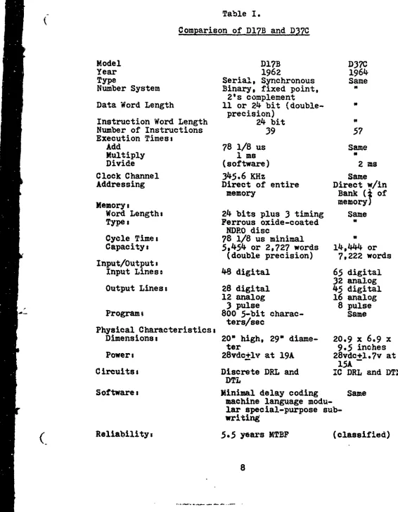
D17B Comparison. Both the DI7B and the D37C computers were designed and built by Autonetics, a division of North American Rockwell, for the real time purpose of guiding and controlling an ICBM from launch to detonation. Because of this, there are many basic similarities between the two. They are both synchronous, serial machines with fixed head disks for primary memory. They have 'two-address instructions, half and whole word precision, and many similar instruction oper-ator codes. The differences in the two computers are based mainly upon their differing technologies. The D17B was built
in 1962 using transistors and other discrete components to realize its logic circuits (Ref 6). On the other hand, the D37C was built in 1964 using small scale integrated circuits
and discrete components only in the internal power supplies.
Table I Summarizes the comparison of the two Minutemen
compu-ters.
D37C Characteristics. The D370 computer consists of
four main sectionsi the memory, the central processing unit
(CPU), and the input and output units. These sections are
enclosed in one case shown Ln Fig. 1.
The memory is a two-sided, fixed head disk which rotates
at 6000rpm. It contains 7222 words of 27 bits. Each word contains 24 data bits and three spacer bits not available to
the programmer (Ref
4).
The memory is arranged in 56chan-nels of 128 words each plus ten rapid access chanchan-nels of one
to sixteen words. The memory also Includes the accumulators
'2• and instruction register (Ref
3).
""GE/AE/74-16
Table I.
Comparison of DI7B and D37C
Model D17B D37C
Year 1962 1964
Type Serial, Synchronous Same
Number System Binary, fixed point, 2's complement
Data Word Length 11 or 24 bit (double-precision)
Instruction Word Length 24 bit
Number of Instructions 39
57
Execution Timess
Add 78 1/8 us Same
Multiply 1 ms
Divide (software) 2 ms
Clock Channel 345.6 KHz Same
Addressing Direct of entire Direct w/in
memory Bank ( of
MemoryL memory)
Word Lengths 24 bits plus 3 timing Same
Type, Ferrous oxide-coated
NDRO disc
Cycle Times 78 1/8 us minimal
Capacity: 5,454 or 2,727 words 14,44 or
I (double precision) 7,222 words
Input/Outputa
Input Liness 48 digital 65 digital 32 analog Output Lines: 28 digital 45 digital
12 analog 16 analog
Pr3 pulse 8 pulse
S-Prorms 800 5-bit charac- Same
ters/sec Physical Characteristics:
Dimensions: 200 high, 290 diame- 20.9 x 6.9 x
ter 9.5 inches
Power: 28vdc+lv at 19A 28vdc+l *7v at 15A
Circults: Discrete DRL and IC DRL and DTL DTL
Softwares Minimal delay coding Same machine language
modu-lar special-purpose sub-writing
(
Reliability,
5.5 years MTBP
(classified)
[image:22.676.26.592.78.806.2]GE/ E/74-16
/
Figure 1. Photograph of a D37C Computer.
9
GE/"E/74-16
The central processor (CPU) is a serial device realized
from small scale integrated circuits using diode-transistor
logic. It contains 57 instructions including hardware
multi-ply and divide. They also include provisions (flags) for
al-tering or repeating instructions. The CPU operateq on data
in the full word (24 bit) or half word (11 bit) mode. Data
is represented as binary fractions in sign plus two's
comple-ment representation (Ref
3).
Both Minuteman computers contain elaborate input/output units. These units are designed for real time operations of
gyro sensing and torquing, accelerometer reading, gimbaling
rocket engines and arming nuclear warheads. Because of the
specialized nature of these I/0 units they are not directly
(
compatible with usual minicomputer peripherals. Overcoming this difficulty and adapting the I/0 units to a more conven-tionalI/0
scheme is the topic of a thesis by Lt. Joseph Theriault entitled Design Expansion of the D17B Computer In-put/Output Facility for General-Purpose Applications.Adapt-ing the D37C's I/0 units is the topic of Chapter IV. The in-put/output signals, as well as the memory and CPU, are defined further in Appendix A.
Scope and 0z1anization
This section defines the scope of this report, explains some of the conventions used, and describes the structure of the remaining text*
(
Scope. This paper provides the foundation for future work on converting the D37C computer for general use. It does10
GE/EE/74-16
so by providing solutions to the problems involved in initial
set-up and operation of the D37C. This report also presents
alternate (some untried) solutions in case the ones chosen
here are impractical in other situations. There is enough
information in the body and appendix to allow an average
Electrical Engineering graduate student to perform equivalent
work on a bare D3?C computer.
Conventions. In order to maintain some consistency with
Minuteman documents and previous thesis, and to minimize con-fusion, certain conventions will be maintained throughout this report. Complemented literals in logic expressions are represented with an appostrophe rather than an overline, i.e. A' = A. Positive logic will be used throughout except where
indicated. Signals are renamed after they are interfaced (.level shifted). The new names are acronyms which better re-presents the signals' purpose or they have one or two letters missing from the original label. Naming intermediate signals
in a circuit has been kept to a minimum to avoid confusion. Wiring labels for circuits are given in three
alphanu-meric numbers as shown and explained below
-11-32-3
1) 2) 3)
1) Ii - indicates the boazd, This term will always
start with a letter and may be omitted if the entire schematic
is on the same circuit board and diagram.
2) 32 - indicates art IC socket or socket location. This number can range from 1 -
35
and may be omitted if theGE/,E/74-16
3) 3 - indicates a pin location. This can range
frov, 1 - 24.
Stru.tture. A structure was selected to present the ma,-terial in the most logical and least confusing manner. Each problem investigated is presented in a separate chapter because the problems are relatively independent. As a result, each chapter is relatively independent, containing all necessary information for that section and leaving unnecessary details for the appendix. Each chapter will contain the
specifica-tions, organization, design, and implementation for that sec-tion of the system. This structure aids the report's
utili-zation as a handbook for building an equivalent system or as a guide for troubleshooting and maintenance. Because of the
separateness of the chapters, they may be removed, updated, or added to with relative ease.
-(
-- 12
"GE/EE/74-16
II* External Support Systems
C
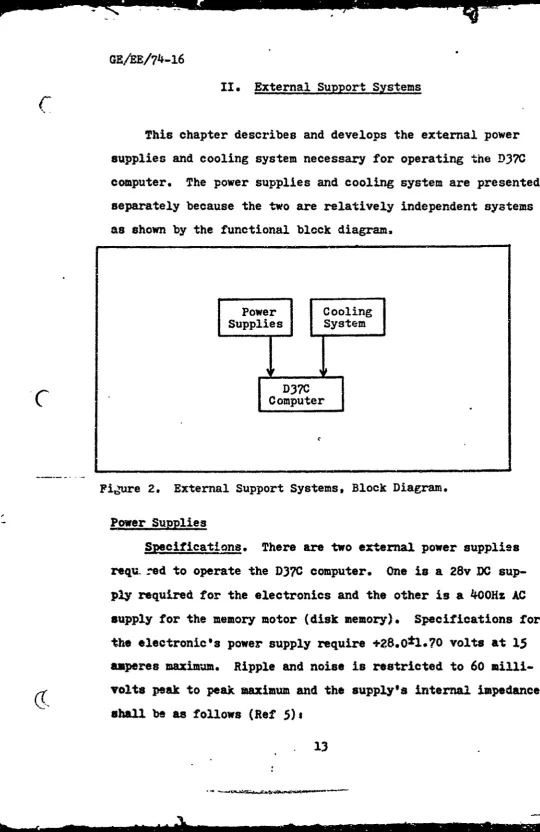
This chapter describes and develops the external power
supplies and cooling system necessary for operating the D37C
computer,
The power supplies and cooling system are presented
separately because the two are relatively independent systems
as shown by
the
functional block diagram.Power Cooling Supplies System
D37C
C omputer
[image:27.660.56.597.7.840.2]C
Figure 2. External Support Systemsq Block Diagram.
Power Supplies
Specifications.
There are two external power supplies
requ. red to operate the D37C computer.
One is a 28v DC
sup-ply required for the electronics and the other is a 40OHz AC
supply for the memory motor (disk memory).
Specifications for
the electronic's power supply require
+28.0•1.70
volts at 15
amperes maximum.
Ripple and noise is restricted to 60
milli-volts peak to peak maximum and the supply's internal impedance
shall be as follows (Ref 5)s
GE/EZ/74-•I6
Frequency Impedance (ohms)
dc to 1 KHz < .05
1KHz to 1O.VHz < 0.7
100KHz to 500KHz < 6
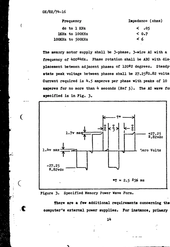
The memory motor supply shall be 3-phase. 3-wire AC with a frequency of 400*4Hz. Phase rotation shall be ABC with dis-placement between adjacent phases of 120*2 degrees. Steady-state peak voltage between phases shall be 27.25±0.82 volts. Current required is 4.5 amperes per phase with peaks of 10
amperes for no more than 4 seconds (Ref
5).
The AC wave form specified is in Fig. 3.T* >
l.7v ma& +27.25
±. 82vdc
*
I
2..
4v max
-Aero Volts
-27.25
-*. 82vdc
•- *T =2.5 :t5% ms
Figure 3. Specified Memory Power Wave Form.
There are a few additional requirements concerning the computer's external power supplies. For instance, prizary
[image:28.676.24.575.28.830.2]GE/EE/74-16
power (28vdc) muRt be disabled within 10 milliseconds if the voltage exceeds +30.3vdc. Also, modules should not be installed
or removed from the computer chassis if any power is on except memory power. Memory power may be on with primary power off but the converse is not true. Also primary power should not be on without a complete set of modules in the machine. At initial turn on only, over-current sur•-es may exist for a max-imum of 45 milliseconds. Finally, the memory power current should stabilize at 3.3 ampere or less when the disk reaches synchronous speed (or approximately six seconds after turn on)
(Ref
5).
Oranization. The specifications mentioned are those required for a test situation in which the conditions on board the rocket must be simulated. The primary power specifica-tlo.s, therefore, are designed to simulate a battery or
bat-tery-generator
source in the missile. It is also assumed thememory power requiterehnts are designed to simulate the )utput
of a solid state AC generator package which is also on board
the missile. Because of the criteria behind the strict power specifications, it may be necessary to relax the requirements
in order to utilize available equipment.
For instance,
con-versations with Mr. Fisher and examination of surplus memory
test equipment indicate the memory waveform may be replaced by a 22vrms sine wave. This is important because in many ap-plications a 400Hz sine wave will be much easier to produce than the specified waveform.
C
MNany solutions to the external power problem become
pos-15--GE/*EE/7lJ-l6
sible if one keeps in mind that specifications may be relaxed for a less harsh environment such as a classroom or labora-tory. Both supplies may be built from scrath or bought if commercially available. The primary power may be sourced from
batteries, a power supply to convert line AC to 28Vdc, or by
"a motor-generator device. The memory power may be supplied by
"a circuit built to produce the specified waveform or by a mo-tor-alternator combination to prod-ace sine waves. There is also the possibility of converting a memory motor supply from
& scrap D17B computer since the power requirements are very similar.
D-esign. The easiest available method of supplying power to the computer was chosen for AFIT's applications. This
con-(9C
sists of taking advantage of an elaborate power generationand distribution system located in AFIT's school of engineer-ing. A centrally located generator room is capable of
supply-ing both the 28vdc at 15 amperes and the 400Hz 3 phase power
for the memory motor.
Power from this room is routed
through-Z
out the building and available at power panels in each
labora-tory. This system of power has proven sufficient and reliable
for running a D17B computer which also requires 28vdc.
The power supply section of the computer console at AFIT includes step down transformers for the memory power and addi-tional power supplies for console electronics. The normal op-erating range for AFIT's
400Hz
alternator is 125 to 250V and is therefore unstable at 22vrms, To counteract this,trans-formers are used in the console to step down the voltage, The
GE/tE/74..l6
computer power system is combined with power supplies for other circuitry to provide a centralized power location in the con-sole. These additional supplies include regulated +5, +12, and -12vdc sources.
Realization. Implementing this type of power system in-volves fabricating cables to run the power from panel to con-sole, building a distribution system inside the concon-sole, wiring step down transformers for memory power, and providing appro-priate safeguards and power control. Fig. 4A shows a schema-tic of the computer power system. The dc power is provided with a 20 amp circuit breaker to control the power and to pro-tect the computer from over currenta. There are also circuit breakers on the power distribution panel for additional
pro-SC tection.
The memory power voltage is stepped down with two trans-foruers. Each transformer is actually composed of two 6.3v filament transformers with the primaries in parallel and se-condaries in series. The transformers were designed for 60H% but operate well at 40OHz since the cores have less time to saturate. Each secondary can supply 6A continuously. The 22 vras, 40OHz power is supplied to the computer when 180vrms is applied to the primaries. Switching memory power is done with the circuit breaker switch on the power panel.
The schematic for the console power supplies is shown in Fig. 4B. Power supplies salvaged from surplus equipment sup-ply the regulated current required by the console electronics. Each is fused for its maximum output and switched with a
con-17
-GE/ME/74-16
C
"Circuit Breaker
I-/1.. .
+28 ±,.7vdc to
WI
I
icomputer
Gnd to computer
4-05A
E 4-5AA
to computer B
4.5A5
4A Computer Power Control Circuit
p-,-,+ 6A
'6
2k1
an* Chassis
o iground
I
+5
Signal
?i9~4 soeground
Indi-a- 'Power ~
tor Indicator
S4B Console and Cooling Pnwer Control Girut
Figure 4. PDU Circuits.
!!
•
'18
GE/1EE/74-16
son power switch.
There are two grounds or commons in the console which are
called chassis ground and signal ground. The chassis ground
is to prevent shock and other electrical hazards when working
with the console.
The ground line from the 115v ac source,
the panel grounds and the ground wire from the 40OHz
alterna-tor are all tied to chassis ground.
Neither side of the 115v
ac source is tied to either ground. The signal ground acts
as a power -return for all dc sources and as a common for all
sigrals. The negative side of the +28, +5 and +12vdc sources,
and the positive side of tre -12vdc supply are tied to signal
gr3und. The two grounds are not intended to be tied together
ir. the console though this may occur with no problem (for
in-s ance, another experiment uin-sing the power panel may tie the
-28vdc to ground).
Power distribution in the console originates at the Power
uistribution Unit (PDU). The PDU acts as a patch panel for
tiring the power systems and provides a central location for
)ower troubleshooting and pow..r routing. Each circuit board
.n the conrole has its own power and signal ground lines
run-ing to the PDU. This was done to eliminate some accumulated
i oise on the power lines and to insure that multiple
connec-lions did not reduce the voltages. The PDU is illustrated in
Fig. 5.
C:ooling SysteM
t
Specifications. The cooling requirements for the D37C¢caputer are given in the Test and Recycle Specs (Ref 5). The
Gz/tE/74-l6
N
Signal
Switch
Common
Switch - in 1
;witch +12v in + 12v out 1 4
-Ce
in
+5v in
+5 0 tQ
f
;d in
f STare 028v
Return ou .
+28v 28v out]
0
E
-...
i J20GE/•E/74-16
computer's electronics are completely enclosed in a metal
cas-ing and cooled by coolant circulating through the casing's hollow walls. The liquid coolant is a water solution of ..1 to ,22 percent by weight of sodium chromate and distilled or deionized water having a minimum specific resistance of 175,000 ohms. The temperature of the water shall be +40 (+10, -5)
degrees F at the inlet and +56 (+7, -4) at the outlet and at no time should the outlet temperature exceed 70 degrees F
(Ref 5). The cooling system must remove 350 watts of heat dissipated by the computer.
Organization. The mentioned specifications are, as before, designed to simulate a rocket environment for testing purposes. The requirements may have to be relaxed to utilize available S
C
equipment. This is feasible as long as a suitable environmentfor the circuits is maintained. The computer may, in fact, be operated outside the speoieied- t•ae•_ratit* rage ea long as moisture does not form on the inside walls (too cold) cZ as long as the outlet temperature does not exceed 70OF (Ref 5).
Relaxing the cooling requirements results in a wide range of
possible solutions including air cooling.
The computer cooling system may consist of any combina-tion of open loop or closed loop systems using either liquid or air heat transport. A refrigeration unit may be used to remove heat from the coolant or the computer itself may be used
as an evaporator in a refrigeration cycle. Tap water may keep
(:
the computer cool in an open loop system. To keep hard water deposits from clogging the cooling ducts, tap water may be used21
GE/EE/74-16
to remove heat from a coolant in a combined open and closed
loop system* Other cooling systems may include removing the
computer covers and forcing air in and around the circuits to
cool them directly.
Design. The system selected for cooling the D37C uses
forced air and circulating liquid. Since no refrigeration
unit or tap-and-drain were available, this system was chosen
as the most effective and easiest to implement. The D37C was not designed for air cooling but air can be forced down between the circuit boards and around the IC's. At the same time,
distilled water circulates through the walls to lower heat gradients and to cool those parts not sufficiently cooled by air. In this way, the IC's act as their own radiators and are cooled more directly instead of the heat traveling first to the computer walls. This justifies cooling with room tempera-ture air (around 70°F) and allowing the coolant to raise above
70?.F Removing a cover for air cooling, however, increases
the poasibility of dust and foreign objects entering the casing.
-. Precautions should be taken to keep the insides clean because
of the closeness of IC leads and the possibility of foreign
object shorts.
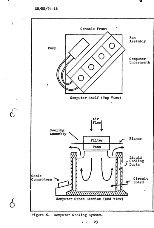
Realization. This system was implemented with four
"Muf-fin* fans to circulate the air and a small pump to circulate
the liquid (see Fig. 6). The four fans are capable of
circu-lating two to four hundred cubic feet of air per minute.
Be-cause obstructions in the casing prohibit flow through air,
only one cover was removed. The side of the computer opposite
22
GE/EE/74-l6
Console Front
Fan
Pump
,0 Assembly' 0 Computer
Underneath
/
//
Computer Shelf (Top View)
Air
Cooling
II
Fans
- • - Liquid
2 Ducts
Cable
Connectors
N
CircuitBoard
Computer Cross Section (End View)
[image:37.668.59.576.25.788.2]GE/EE/74-16
the cable connectors was removed and the fans, bolted together,
were placed over the center of the circuit boards on the card
end protectors. This leaves approximately one inch on either
side of the fans for exhaust air. Some "horse-hair" packaging material was placed over the fan intakes for crude filtering. Flanges on the fan assembly prevents objects from dropping into
the computer housing and acts as a manifold to reduce recircu-lated air. A pump with two to three gallons per minute capa-city was placed on the shelf with the computer and connected with plastic hoses. No special hose connectors are necessary
since the friction fit is water tight. The whole system is controlled by a front panel switch as indicated in Fig. 4B.
This system is not sufficient for continuous duty but is the most effective cooling scheme available. The circulating liquid temperature gradually increases when the system is
run-ning. When the temperature reaches 1000F (about 20 minutes) the primary power is removed while the system cools or while the liquid is replaced.
Gac
--Summar. it has been shown thdt external systems for the
D3*C computer can be implemented easily. This has been done by supplying the needs of the computer rather than trying to meet the specifications designed to simulate a rocket
environ-sent, These mentioned systems are just one solution of many that can be built. Simpler systems and more complex systems are possible. For example, the power circuit may be expanded to an automatic system that shuts off when temperature or
SGE/EE/T4-16
tages get out of tolerances,
There is, presently, an additional constraint for build-ing systems at AFIT. The D37C computer AFIT possesses is
classified "secret' due to previous information on the memory
disk, It is necessary, therefore, to remove the computer from
the console and put it in a safe after each day's use. This
means that every system associated with the computer must be
easily connected and disconnected. This constraint will not
be present when the computers become surplus.
System Interconnection. The external support systems are
located in the cabiret as shown in Fig. 7 and electrically
interconnected as shown in dig. 4. The power shelf (bottom)
pulls out to provide easy access to the Power Distribution Unit (PDU) and power supplies. The computer shelf also pulls out to allow easy hook up of power, cooling and cables. All
Switches for power and cooling are located on the front panel!
Recommendations. The following recommendations are made
in the interest of improving the system or as experiments io
better understand the limits of the machine.
i. Because of the closeness of circuits in the
com-puter there is a chance of foreign object shorts with the
pre-sent ccoling system. It is recommended that the computer be
cooled only with a liquid system of continuous duty cycle if
the equipment becomes available. Until then, efforts for a
better filtering system would increase the present system's
reliability by keeping the close circuix leads clean.
2. The power system may be expanded to include
GE/.-
/74-16
Front Panel
Cooling _
Pans
D37C
Computer -II
Power____
Supplies -___
Power
[image:40.660.66.620.10.820.2]Dist.-Unit
- ir; • = -;--• " -" -_ .9...' --
-"GE/EE/74-16
sole switching and automatic monitoring devices. Such a
sys-tam would add complexity but it may also inerease protection from power faults.
3.
As an experiment, the speed of the computer could be increased by increasing the frequency of the memory motor power. Since the memory motor is a three phase synchronous motor it can be made to run faster by increasing the power frequency. In turn, since the clock and other timing pulses come from tracks on the disk the whole computer would workfaster. Before this in- attompteda hvvever, there are many considerations to make, There 48 some indication in Reference
3 of the electronics being capble of a one mer-a Hz clock which
is almost a three fold increase. The motor, however, is not
expected to operate that fast (almost 18000rpm). The reduced motor torque caused by higher frequencies can be offset some by Increasing the voltage. Flowever, the bearing wear and disk stresses are unknown at higher speeds. The read and write heads may also be unreliable at higher speeds, In all, the total increase in computer speed cannot be expected to be much
2?
-C'
G.E/EE/74_i6
III. Control and Monitor Systems
After supplying the computer with proper power and ccooling systems, it is necessary to control and monitor i~ts functions before it is suitable for any application. This is done by properly controlling the computers modes anid developing a sim-ple memory loading scheme. In order to monitor the computers functions the major modes must be- indicated a~nd the contents of selected registers must be dis~played~. in effect, the moni-tor and control circuits provide simple 1/0 for the computer which alone may be suffikiett for many applications. The
mon-itor and control systems fit into the total system as shown in
pigs 8.
Interfacine
Interfacing the conputer's signa-le, matches voltags
lev-els, imp'sdances, arnd current requiremenui tr. thsexterna.l QiTTL)
logic circuits.* This 18 neceasary because the external loAgic
is realized from
TTL*zxiil and m~edium P_*le int~egrated
cir-cuits. Thiý-a circuits were
uUsd instead of buildingCompati-ble dXiveeete logic because ltiey were wala~laCompati-ble & easy to des-ign
witsh, came in logic '"blcoeks` of several gates per chip, arn4
have relatively. highs r-isa immunity., Most compute.-
signals
va-ry from -1.5
t~+12.yoltps &-,&are t
re:*fae incompatibals with
týe 0 to
+5
veltage levels of 11IL logl.
Nea~rly all of the
*isgnalap. 1%oth input arid output, may bo interftced by using
(
li-ne drivers arA line raeiovers in
ie
fors.
Some re-quire op..
araxtio-nA!
amplifier
vircuits and others need inverters Ito
GE/EE/714-16
SControl I'•nterfaceI
-
I
[image:43.660.9.581.0.838.2]Monitor
Figure
8.
System Block Diagram.
vert from negative to positive logic.
The following investigation will indicate if a signal has
to
be interfaced or if it is compatible with the circuit. For
a complete listing of interfaced signals and schematics see
Appendix B.
Mode Control and Monitor
Controlling and monitoring the computers modes of
oper-ation requires some very simple circuits. It is necessary,
however, to have some understanding of the modes and how the
computer
functions (Ref 5,11,
and
3).
Major Modes. The computer can .operate in several modes
and submodes which are of particular interest to the operator/
(
progammer.
These modes, with descriptions, are listed below&
(9
1) Compute Mode - While in this mode the computerexe-29
GEAE/74-16
cutes an internally stored program.
la) Single Cycle Submode - In this submode,
the computer executes one stored instruction.
2) Noncompute Modes Load - In this mode the
compu-ter is capable of receiving information on the characcompu-ter input
lines (Ref 5). This mode and the character lines are used for
program loading and are discussed later.
2a) Fill Submode - This is a submode of the
above noncompute, Load Mode and is the mode which information
may be entered into the computer memory.
2b) Verify Submode - In this mode the contents
of computer memory may be verified (or compared) against
in-formation on the character input lines.
3) Noncompute Modes Nonload - The noncompute-non-load mode is defined by the following major submodes.
3a) Sync Submode - In this mode the computer's
electronic section is brought into synchronization with the
rotating disk memory. This is done by synchronizing the bit
counter with the sector track (see Appendix A).
3b) Manual Halt Submode - In this mode the
computer is in a wait state.
3c) Program Halt Submode - This mode is
en-tered from the compute mode by an executed instruction. In
this mode the computer is in another wait state.
3d) Conditional Fill Submode - This mode
pro-vides a security precaution to prohibit unauthorized personnel
(
from loading the computer memory. It prohibits entry into theGE/F.E/74J-16
c
fill submode unless the first four words entered agree with the first four words of channel 12, bank 0.4) Interruption and Recovery Mode - During this
mode the computer, upon detection of a simulated transient
disturbance, will interrupt normal operations, enter a dormant
state, and then recover to the same program location.
Specifications and Organization. It is desired to have
some control over the computer's transitions between modes and
to have some indication of the current operating mode.
Two of the modes serve little use in general purpose
ap-plications and are therefore eliminated or disabled. These
modes are the conditional fill submode and the interruption
and recovery mode. For most applications the security facet
of the conditional fill mode is nct needed and only serves to
hinder the entrance into fill mode. The conditional fill mode
may be bypassed by enabling the PFc line and applying a true signal. The line is enabled by making an electrical
connec-tion on Logic No. 10, connector J216, between test points B36
and B32 (Ref 5). Once this is done the fill mode may be
en-tered directly by applying a true (-4 to -24 vdc) to Pao. The
interrupt and recover mode forces the computer into a dormant
state (all internal power supplies disabled) which would have
little use in most applications. The interrupt mode may be
avoided by not programming a simulated random dump (SRD)
in-struction and applying a false signal to the Idt input term.
A false for the Idt term is +12+8 vdc input or an open
cir-cuit (Ref 5). Controlling the remaining modes is necessary
GE/ E/74-l6
for effective computer control.
The sync mode must be entered each time the machine is
turned on in order to synchronize the computer. The sync mode
is entered by applying a true signal on the master reset line
(Mrc) for a minimum of 55 psec after the memory has reached
synchronous speed. A true for Mrc is -15 (+11,-12) vdc and a
false is +12+8 vdc or an open circuit. The computer
automa-tically exits the sync mode to the manual halt mode (Ref 5).
The compute mode is entered only from the manual halt
mode in one of two ways. Normal execution is started by
chang-ing the halt prime (Khc') input signal from false to true for
at least 200 microseconds. Halt prime may then return to
false. The single cycle prime (Ksk') input signal remains
true throughout the sequence, The compute mode may also be
entered for the execution of one instruction and then returned
to manual halt by the initiation of the single cycle sequence.
This sequence calls for Ksk' to change from true to false then
Khc' is changed to true for at least 200 microseconds. Then
Khc' returns to false and Kok' returns to true (Ref
5).
Timing
diagrams for both of these sequences and voltage levels for
the signals are given in Fig. 9.
As mentioned earlier, a true signal on the Fac line will
put the computer into noncompute-load mode from either the
manual halt or program halt modes. Once in this mode,
char-acter inputs to the computer may be made as described in the
Program Load section of this chapter. The character inputs
C--can
change the computer modes as well as load the memory.32
GE/ZE/74-l6
C
T
Krk- F
T
Kek * 20F
Ksk' F
a) To enter Compute
T
Krk' F
T
Khc' - i 00 ps FT
f
Ksk Fb) To enter Single Cycle
Krk - F
T
Khc - F
T
Ksk'
F
c) To enter Manual Halt
Tn
(C
I
Figure '9. Timing Sequences for Mode Control-.
GRE/7E?4-16
Commands can be given to change from the fill submode to the verify submode or from verify to fill. A compute command re-moves the computer from noncompute-load and enters it into manual halt. A halt command charges it to program halt (Ref
5).
The manual halt submode may be entered several ways. It may be entered from compute by the single cycle sequence already mentioned or by the following sequence of inputs. Initially
the halt prime (Khc') signal changes to a quiescent false state* Tnen run prime (Krk') changes from false to true, The single cycle prime (Ksk') signal will remain true throughout the sequence. see Fig. 9 (Ref 5). This same signal sequence will enter the computer into manual halt from program halt. Manual halt may also be entered from load mode by a compute
C
command, as mentioned in the preceeding paragraph, or by a parity or varify error (see program load section). Exit from the manual halt mode may be to compute or noncompute-load. by methods already described.The program halt setmode may be entered in one of two ways. One is by a