The Bendix G-20 System
FOR HIGH-SPEED COMPUTING
A TECHNICAL INTRODUCTION
-J
I
A Technical Introduction
THE BENDIX
CONTENTS
The G-20 System
Information Flow
Accessories
Progr.amming
Specifications
Pages 1-2
Pages 3-6
Pages 7-9
Pages 11-16
..
The G-20 System
A wide variety of systems with widely different characteristics can be assembled from these com-mon elements. Information can pass from one element to another without passing through the central processor enroute. The units can be con-nected together in such a manner that desired elements operate simultaneously.
For example:
A scientific computing system can be assem-bled from a central processor, control console, magnetic tape units, a card and printer
coup-ler, a high speed printer and punched card equipment.
An independent system for tabulation of in-formation held on magnetic tape, can be assembled by connecting together a magnetic tape unit, a high speed printer and a control buffer.
A business data processing system with in-put/output units operating concurrently can be put together by combining a central pro-cessor, control console, card equipment,
mag-netic tape units, control buffer and a data
communicator.
The user can change the nature of his system at will, since elements of the same type are
inter-changeable. The change from one system to another can be made under program control if desired.
Programs for the new Bendix system are writ-ten in an easy to use language. The programming
language may be algebraic or symbolic. Input and output data may be expressed decimally 111 either fixed point or in floating point form.
THE G-20 COMPUTER
The G-20 computer is the central processor of the Bendix data processing system. The processor is built of solid state components, and includes a random access, expandable, magnetic core mem-ory. Its internal computing speed is very high
since the bits of a word are handled simultane-ously during information transfer to and from the memory, and during all ar,ithmetic operations.
Memory
The internal memory of the G-20 consists of from one to eight magnetic core modules of 4096
words each. Two memory modules can be located
in the G-20 cabinet. Additional modules are held in adjacent matching cabinets. Each cabinet holds
either one or two modules. Each word in the
eight modules is directly addressable.
Arithmetic Operation
Numerical information may be read prior to computation, and tabulated after computation, with the decimal point in any specified digit position. For example:
1,234,567,898.76
+
666,666,000.00 1,901,233,898.76Or numbers may be read and tabulated in float-ing decimal point form. For example:
123,456,789,876 x 10 2
+
666,666 x 10 3190,123,389,876 x 10
The arithmetic circuitry provides precision greater than a word length for both numbers operated on and results of the operation. A full
length number (12 decimal digits) can be stored in the memory in two sequential word locations.
Or if less precision is required, the number may be stored in the memory in a single word location. Either double precision or single precision
com-putation can be automatically performed.
The accuracies and speeds of computation are listed on page 18.
Command Structure
When the algebraic or symbolic program is
entered into the computer, it is automatically transformed into a stored program in the internal
language of the computer. Some techhical reasons why a transformation can be made completely and efficiently are listed below.
The effective length of an internal command is variable; it may consist of any number of words.
The basic machine command specifies a single operand. Either the value of the operand, or its address may be written in the command. The
operand may be specified in the command directly by a single address, or indirectly by combining the contents of any number of addresses written in the command. The latter feature provides very
flexible index register operation in which any ad-dress in the memory and any number of adad-dresses may be used for indexing.
v
Information Flow
CONNECTION OF UNITS
All types of elements in the Bendix Data Pro-cessing system attach to common communication lines. A compact but powerful punched card
com-puting system is shown in Figure 1. A magnetic tape unit (MT-10) can search for a specified block of information independently of any other operations on the line. Operation of the card
reader or the tape punch can be concurrent with internal computation. By adding from one to
seven MM-10 auxiliary memory modules of 4096 words each, the internal memory may be
ex-panded. The communication system may be e x-panded by adding elements to the communication
line and by additional communication lines. Different types of system elements, including a central processor and auxiliary memory, and the manner in which they tie to a communication
line, are illustrated in Figure 2. A line can be
any desired length up to about 1500 feet and can
handle information at whatever rates the units attached to it operate. As many as 38 direct
con-nections may be made to a single communication
line. Up to 32 units can be connected to the foul' data communication lines of the data
communi-cator (DC-ll). The units can be spaced along a
communication line in any manner desired.
Without passing through the central processor, information can be sent from one element on a communication line to another via the data com-municator (DC-H) or control buffer (CB-H) since these units also control data flow. The DC-l1
or CB-ll can be used to instruct any input device
to send information to any output device attached
to their lines.
In Figure 3, information from magnetic tape
via the DC-1I may be tabulated by the printer
while the central processor is performing internal
computation or communicating with the control console. (CC-10).
Multiple pairs of input/output elements can communicate concurrently. Input/output elements
communicate with each other under control of the central processor, DC-ll, or CB-l1. The addition of control buffers or the data communicator to the system permits additional pairs of input/
out-put elements to communicate with each other at
the same time.
COMMUNICATION LINE
• A COMPACT PUNCHED CARD
• DATA PROCESSING SYSTEM
FIGURE 1
DIFFERENT TYPES OF UNITS THAT ATIACH TO A COMMUNICATION LINE
DATA COMMUNICATION LINE fli
DATA COMMUNICATION LINE 112
DATA COMMUNICATION LINE .3
DATA COMMUNICATION LINE ,,4
The figures that follow are examples of feasible systems or sUb-systems.
DATA COMMUNICATION LINE #1
DATA COMMUNICATION LINE
ICATION LINE
NICATION LINE #4
FIGURE 3
A MAGNETIC TAPE DATA PROCESSING SYSTEM
PRIMARY COMMUNICATION LINE
SECONDARY COMMUNICATION LINE
FIGURE 4
THE G-20 CENTRAL PROCESSOR, DC-ll AND CB-l l CAN ACT AS CENTERS FOR COMMUNICATION BETWEEN OTHER UNITS.
A single communication line handles a number
of messages at the same time by programmed multiplexing of the messages. Additional
commu-nication lines can be added as necessary via the DC-ll and CB-ll. Two communication lines can
be attached to a control buffer; up to four
com-munication lines can be attached to the data communicator.
In Figure 3, low speed elements are attached to
a card coupler (PC-lO) and the high speed line
printer (LP-l2) is attached directly to a
commu-nication line. By using a DC-ll in a G-20 com-munication system, reading of cards, computing
and line printing can occur simultaneously.
Magnetic tape units can be switched from one communication line to another under program control. Using the switching feature possessed by
both magnetic tape units and control buffers, a
control buffer can control a card punching
oper-ation on one communication line while the central processor is communicating with magnetic tape units on another communication line.
In the system shown in Figure 4, the central
processor can receive information from the mag-netic tape system on the left, while the control buffer is modifying and transmitting information to the other tape system. Then, under program control, each magnetic tape system can switch to
its other line and the central processor can
com-municate with the tape system on the right while
the control buffer is communicating with the magnetic tape unit on the left.
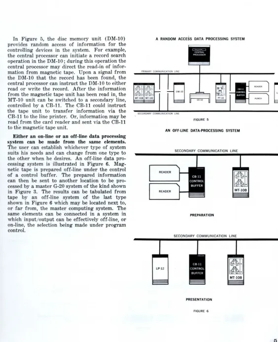
In Figure 5, the disc memory unit (DM-IO) provides random access of information for the
controlling devices in the system. For example,
the central processor can initiate a record search
operation in the DM-IO; during this operation the
central processor may direct the read-in of infor-mation from magnetic tape. Upon a signal from
the DM-IO that the record has been found, the
central processor can instruct the DM-IO to either
read or write the record. After the information from the magnetic tape unit has been read in, the MT-IO unit can be switched to a secondary line, controlled by a CB-ll. The CB-ll could instruct the tape unit to transfer information via the CB-ll to the line printer. Or, information may be
read from the card reader and sent via the CB-ll to the magnetic tape unit.
Either an on-line or an off-line data processing
system can be made from the same elements.
The user can establish whichever type of system suits his needs and can change from one type to the other when he desires. An off-line data
pro-cessing system is illustrated in Figure 6.
Mag-netic tape is prepared off-line under the control of a control buffer. The prepared information
can then be sent to another location to be
pro-cessed by a master G-20 system of the kind shown
in Figure 3. The results can be tabulated from tape by an off-line system of the last type
shown in Figure 6 which may be located next to,
or far from, the master computing system. The
same elements can be connected in a system in
which input/output can be effectively off-line, or
on-line, the selection being made under program
control.
A RANDOM ACCESS DATA PROCESSING SYSTEM
PRIMARY COMMUNICATION LINE
MT·IOB MT-IOC
SECONDARY COMMUNICATION LINE
FIGURE 5
AN OFF·LlNE DATA·PROCESSING SYSTEM
SECONDARY COMMUNICATION LINE
READER
1
1
1
:
1
READER MT·IOB
PREPARATION
SECONDARY COMMUNICATION LINE
lp·12
~
MT·IOB
[image:10.615.301.603.61.584.2]PRESENTATION
[image:10.615.31.596.66.758.2]INPUT/OUTPUT
Elements attached to a communication line are addressed via the unit which controls transmis-sion of information along the line. The controlling unit may be the central processor, the data com -municator, or a control buffer.
To initiate a central processor input or output operation, the programmer specifies the operation to be performed, the number of the unit on the communication line, and the portion of the int
er-nal memory which is to be either filled or read
out. The portion of the internal memory is
indi-cated by stating the beginning address and the
total number of word positions involved.
Input/output information may be transmitted via up to four DC-ll data communication lines with complete independence. The DC-ll permits simultaneous reading, writing and computing by providing for time sharing of the external me
m-ory. When data flow outbalances computing re-quirements, this capability is especially valuable. All four DC-ll data communication lines may communicate at the same time with one memory
module to which the central processor also has
access. Each of the DC-ll lines is independent in
its operation. When input or output is started,
it is completed independently of the central
pro-cessor.
The DC-ll is instructed by means of a list in
memory. This list consists of the addresses and lengths of segments of data to be transmitted
or received, or of instructions to be transmitted.
By interspersing command segments, the list can be used as a stored input/output program for the
data communication line.
Input/output information, and also instruc-tions, may be sent from the central processor and
stored in a control buffer. The control buffer
can then operate independently of the computer by obeying its own stored program.
When a control buffer has finished obeying its
internal instructions, it sends a signal to the central processor which notifies the computer
o
o
o
o
0
0 0 0
U
that it is ready for additional instructions or for another assignment. Such a signal is called an "interrupt"; it has the ability to interrupt co
m-putation and causes a transfer of control to a
separate program. A command can be written at the end of the separate program to transfer co
n-trol back to the main program.
Interrupts in the data communicator are used chiefly to inform the central processor that the data communication line has completed its tasks. Interrupts are also used to indicate completion of operations that can be set up by the data line and
can continue without further use of the line (for
example, magnetic tape slewing or control buffer
operations) .
An "interrupt" signal can be generated by a piece of terminal equipment as well as by a con-trol buffer or the data communicator.
Multiple Concurrent Operations on One Communication Line
Since each communication line in a system is independently controlled, communications on one
line can occur at the same time as communications on other lines.
Moreover, depending on input/output speeds and the application involved, more than one input/
output operation can be multiplexed on the same
line.
The chart below (drawn out of scale for the sake of clarity) indicates how it is done. The time during which information characters occupy the communication line is a small fraction of the time required for a complete card reading or tape punching operation. When both the card reader and paper tape punch are operating co
n-tinuously, the data from the card reader can be carried on the communication line without inter-fering with the data being sent to the tape punch. Meanwhile, the central processor can be working
with a completely independent program; the
pro-cessing of the independent program pauses for the small intervals of time necessary to receive and store information from the card reader and to send information to the tape punch.
CARD READER OPERATION
o
CARD DATA ON COMMUNICATION LINE PAPER TAPE PUNCH OPERATIONPAPER TAPE DATA ON COMMUNICATION LINE
000
OJ
0 00
00
MULTIPLEXED INFORMATION ENTERING CENTRAL PROCESSOR....
_
...
_
..
TIME - - - -....
CC-10 Control Console
The operator can initiate, monitor, and control
execution of programs from the control console.
The console includes a full-keyboard typewriter
for entering input information and printing o ut-put information. All characters on the keyboard, both upper case and lower case, alphabetic, nu
-meric, and algebraic, can be entered or typed ou.t.
Instructions to the computer can be entered VIa
the keyboard. Type-out is at the rate of approxi
-mately 8 characters per second.
The console also includes a set of indicator lights to provide information concerning the status of
the program being processed.
MM-10 Auxiliary Memory Module
An additional core memory module is similar
in size and characteristics to the G-20 internal
memory. From one to seven additional memory
modules may be attached to the central processor.
The modules extend the directly addressable me m-ory to 32,768 words in increments of 4096 each.
In programming, auxiliary memory is indistin-guishable from the internal 4096 words.
MT-10 A-B-C Magnetic Tape Modules
A tape control unit couples one to four tape transports to either of two communication lines.
One of the four attached transports may be
re-ceiving or transmitting information at any given time. All tape transports may be independently searching for specific blocks of information on tape, in either the forward or reverse direction, at any given time.
A tape control unit can switch from one com-munication line to a second line under control of a program in the central processor or a control buffer.
A tape control unit is mounted in the same cabinet as one of the tape transports it is con-trolling. A single cabinet may be equipped with
either a control unit and one tape transport, a
control unit with two tape transports, or with two tape transports alone. The three different
configurations are identified as follows: Module MT-10A One control unit and one
transport.
Module MT-10B One control unit and two transports.
Module MT -10C Two transports.
The MT-10C must be attached to a tape module
which contains a control unit.
Ten channels are recorded on tape: eight infor
-mation channels, one parity checking channel and one block indicating channel. One reel of tape can hold about 45 million alphanumeric and 90 million numeric characters of information.
Information may be recorded in blocks of arbi-trary length. Tape can be erased and updated in blocks. Information written on tape is checked
for validity by special reading heads immediately after recording.
The tape unit specifications are:
Packing Density 1100 frames per inch
Read-Write Speed
Search Speed
Re-wind Speed
Tape Length
Tape Width
120,000 eight-bit characters per second
240,000 eight-bIt characters per second
240,000 eight-bit
characters per second
(220 inches per second) 3,600 feet
1 inch
When magnetic tape is used for temporarily storing information from the central processor, an eight-bit character may be equivalent to two decimal digits. When a character indicates two decimal digits, the read-write speed is 240,000
digits per second, and the search speed is 480,000
digits per second.
PC-10 Printer and Card Coupler
The Printer and Card Coupler, the PC-10, can
couple a G-20 Communication Line to conventional card machines. The card machines may be a card
reader and a card punch or tabulator. The
maxi-mum configuration is a card reader with veri-fication (2 read stations) and a card punch with
verification (1 punch station and 1 read station).
The card punch may be replaced by a tabulator.
The appropriate adaptor is required for each
station attached.
PT-10 Paper Tape Station
The PT-10 Paper Tape Station consists of a
photo-electric paper tape reader and a tape punch. The reader reads tape of eight or fewer channels
bidirectionally at the rate of 500 characters per
second; it can be stopped on a single character.
The punch punches tape of eight or fewer
chan-nels at the rate of 110 characters per second.
I
DC-11 Data Communicator
The DC-ll Data Communicator connects the
full complement of G-20 input/output equipment
to G-20 memory modules through data communi-cation lines (up to four). The DC-ll permits simultaneous reading, writing and computing with complete input/output independence. Additional system flexibility is provided by the "scatter-read," "gather-write" capability of the Data Com-municator. System speed via the DC-ll is up to
480,000 characters per second for magnetic tape
input/output.
All four DC-ll channels may communicate sim-ultaneously with one memory module to which
the central processor also has access. Each of the four DC-ll communication channels is
independ-ent in its operation. Once initiated, input/output is carried to completion independently of the
cen-tral processor. When a DC-ll communication
channel and the central processor require access to the same memory module at the same time, the central processor waits only the few microseconds required to retrieve or store a word of data.
The DC-ll permits the G-20 to perform
high-speed sorting, file maintenance, and matrix ma-nipulation. Automatic segmentation and memory
allocation of input data and automatic grouping
of output data may be accomplished; any number
of segments of any length or any set of auxiliary memory locations may be involved.
The DC-ll, and individual input/output
equip-ment, can be added at any time without system
modification.
CB-11 Control Buffer
The CB-ll Control Buffer is an independent, information processor which can, operating under control of its own stored program, do editing and
sorting operations outside of the central
proces-sor. By use of a control buffer, information may
be sent from one element to another, and may be modified during transit, if desired, without pass-ing through the central processor.
The CB-ll can couple a G-20 Communication Line to conventional card machines. The card machines may be a card reader and a card punch
or tabulator. The maximum configuration is a
card reader with verification (2 read stations) and a card punch with verification (1 punch
station and 1 read station). The card punch may
be replaced by a tabulator. The appropriate
adap-tor is required for each station attached.
The CB-ll contains 4096 9-bit characters (8 bits of information, 1 parity bit) of magnetic
core storage and facilities to control the flow of information along either of two communication
lines. The CB-ll can switch from control of one
line to control of the other by a programmed
com-mand. Since the CB-ll can receive information
from one line, and can send information to the
other, the unit permits an input device on one communication line to send information to an output device on a separate communication line. Information is transmitted between the control buffer and the central processor at a rate of
167,000 eight-bit characters per second. The use
of control buffers as intermediaries between the
computer and input/output devices permit a
number of input/output operations to be handled
concurrently.
LP-12 Line Printer
The LP-12 Line Printer is a fully buffered, solid
state printer. Since the LP-12 connects directly to a communication line, it has direct communica
-tion with the central processor and other control-ling units. The LP-12 prints up to 63 different characters, 120 characters per line, at a spacing
of 6 lines per inch vertically and 10 characters
per inch horizontally. The drum speed is 1000 RPM. It prints and advances paper independently at rates up to 800 lines per minute, single-spaced,
for a 63-character alphabet and up to 1000 lines per minute, single-spaced, for a 47 -character al-phabet. Numeric characters only can be printed at 1000 lines per minute with mUltiple spacing of
paper.
Information is transferred to the LP-12's buffer at a rate up to 67,000 characters per second. The print format is under program control.
DM-10 Disc Memory
The DM-10 Disc Memory unit provides on-line,
random access of information from bulk storage modules; these modules may contain in excess of
either 10 million or 20 million 8-bit characters (plus parity bit). A parallel-recording technique used by the DM-10 allows all bits of a character to be simultaneously read or recorded. Maximum access time to any record is 170 milliseconds. A verage access time for random locations is 90 milliseconds. Transfer rate between the central
processor and disc memory is 140,000 characters
per second.
The DM-10 is available with either 5 or 9 discs. Each disc is 39 inches in diameter. The rotation
I - - - . - - - _ _ _ _
I
I
I
I
(
v
Programming
PROGRAMMING SYSTEMS
Input statements for the Bendix G-20 system
may be written in algebraic, symbolic, or business
language form. Under control of a programming system that has been entered into the central
pro-cessor from magnetic tape, punched cards, or
paper tape, the computer converts the input
state-ments into a machine language program.
Con-verted programs need not be processed immedi-ately but may be stored on magnetic tape or on other media and called into the central processor for computation when desired.
The machine language program into which the input statements have been converted is in a re
-locatable form. That is, when the program is r e-quested by the central processor it will be
auto-matically entered into any portion of the internal
Algebraic Programming System
Technical problems may be programmed in a standard algebraic form. The algebraic
program-ming system converts the input statements into
a relocatable machine language program.
The algebraic language used for coding is
simi-lar to conventional mathematical expression
ex-cept that certain conventions have been adopted to permit use of a typewriter or line printer. The system is basen on ALGOL, the international
algebraic language.
Symbolic Programming System
Programs may be written in which alphabetic characters specify both the operation to be
per-formed ann the memory location containing the
operann.
For example, a memory location which contains
the salary of a man named Johnson may be
desig-nated JOHNSON in commands; . and the ninth
memory location following the one containing
Johnson's salary could then be addressed in
com-mands as JOHNSON
+
9. The block ofinforma-tion pertaining to Johnson, which may cover any
number of word positions, can be entered into any
available portion of the memory for computation.
To add Johnson's salary to a previou~;Iy
calcu-lated sum the programmer would write "ADD JOHNSON".
It may be desired to repeat the computations
concerning Johnson for a large number of e
m-ployees. A single program may be written in
generalized form for one employee which, by use
of G-20 indexing facilities, will consecutively pro-cess the block of information concerning each
employee. In this case, the locations in the
program previously designated JOHNSON and
JOHNSON
+
9 might perhaps be called insteadSALARY and SALARY +9.
Generalized Business Routines
Generalized programs simplify often used
com-mercial procedures such as sorting, report
prepa-ration, ann file maintenance. The programmer
supplies to the generalized program specific data for the particular problem. In order to prepare
a sorting program, for example, the programmer
supplies information as to the number and size
of the data blocks to be sorted, the fields on
which the sort is to take place, and their order
of priority. The generalized sorting routine then
prepares the remainder of the program.
To use a generalized report preparation
pro-gram the propro-grammer specifies the data to be
ex-tracted from the file block, the arithmetic
opera-tions to be performed, if any, and the manner in which the results are to be printed. Two or more
reports can be prepared simultaneously, if two
printers and a control buffer or data
communi-cator are available. Also, a control buffer can be
used to prepare a report off-line.
File maintenance will ordinarily consist of
sort-ing the group of file changes into the same order
as the main file and then merging the correction
tape with the old tape to produce an up-daten
tape. Here, again, the programmer need only sup-ply data pertinent to the particular run and the
generalized file maintenance program will take
care of the details.
The business programs are based on COBOL,
the Common Business-Oriented Language.
BASIC COMMANDS
The G-20 programming systems have been
built from basic G-20 commands; each basic
com-mand corresponds to a single internal machine
command. When basic commands are used in
programming, complete control is provided over
the detai.led internal operations performed by the computer.
A basic command specifies an operation code
and an operand. The operation code is expressed
mnemonically and the operand as a decimal
num-ber or symbol. Numeric operations are performed
on the contents of an accumulator. The
accumula-tor can hold either double precision or single
precision information.
Numerous "test" commands provide conditional
transfers of control. If the test specified by such a command is satisfied, the next command
exe-cuted is the one in normal sequence. If the test
is not satisfied, the next command in sequence is
skipped.
A partial list of commands is tabulated below.
In their descriptions the terms "Acc" and "X" are used. "Acc" represents the initial contents of
the accumulator before execution of the command.
"X" represents a value specified by the command.
The term "X" in the description means that X is
an operand indicated in the command either
di-rectly or by its memory location. The term "Ad-ress X" in the description means that X is itself
a memory location rather than an operand.
NUMERIC COMMANDS
Arithmetic Commands
CODE
CLA
COMMAND
CLEAR AND ADD
CODE CLS ADD SUB SUN ADN ADA SUA MPY DIV RDV COMMAND
CLEAR AND SUBTRACT
Put - X into Accumulator ADD
Put X + (Acc) into Accumulator SUBTRACT
Put (Acc) - X into Accumulator SUBTRACT AND NEGATE
Put X - (Acc) into Accumulator ADD AND NEGATE
Put - X- (Acc) into Accumulator ADD AND TAKE ABSOLUTE VALUE
Put X + (Acc) into Accumulator
SUBTRACT AND TAKE
ABSOLUTE VALUE
Put (Acc) - X into Accumulator MULTIPLY
Put (Acc) x X into Accumulator
DIVIDE
Put (Acc)
I
X
into Accumulator REVERSE DIVIDEPut
X
I
(Acc) into AccumulatorThe operands and results of arithmetic opera-tions may be expressed as floating point double precision, floating point single precision, or fixed point single precision numbers.
STORE COMMANDS
The contents of the accumulator may be stored in either single precision. or double precision form. When the stored value is read from the memory, it will be read in whichever form it was stored. Consequently, a series of commands may use both single precision numbers and double precision numbers.
Three "store" commands are listed below:
CODE
STS
STD
STI
COMMAND
STORE SINGLE PRECISION Store (Acc) at Address X
STORE DOUBLE PRECISION
Store (Acc) at Addresses X and X + 1
STORE INTEGER
Store Integer Portion of (Acc) at Address X
The "Store Integer" command differs from the other two commands in that only the integer portion of the number in the accumulator is stored. For example, if the Accumulator contains the number "528.17", and the command "Store Integer" is executed, the value "528" will be stored in the memory.
Numeric Test C:;ommands
(Conditional Transfers of Control)
CODE
FOM
FOP
COMMAND
IF OPERAND MINUS
Is X less than zero?
IF OPERAND PLUS Is X greater than zero?
FLO IF LESS THAN OPERAND
Is (Acc) less than X?
FGO IF GREATER THAN OPERAND
Is (Acc) greater than X?
FUO IF UNEQUAL TO OPERAND
Is (Acc) unequal to X?
FSM IF SUM MINUS
Is X + (Acc) less than zero?
FSP IF SUM PLUS
Is X + (Acc) greater than zero?
FSN IF SUM NON-ZERO
Is X + (Acc) unequal to zero?
NON-NUMERIC COMMANDS
Non-numeric or "logical" commands handle a word of information as a code made up of ones and zeros rather than as a numeric quantity.
These commands facilitate sorting and other
operations on alphanumeric characters; each al-phanumeric character is represented by a specific code made up of ones and zeros.
In the commands below, X is interpreted as a 32-position series made up of ones and zeros.
In a "unite" operation, indicated V , two such series are combined in this manner:
101101 value in Accumulator 011001 value X
111101 Result in Accumulator
A "one" appears in the result in each position
In an "extract" operation, indicated A ,two
such series are combined in this manner:
101101 value in Accumulator 011001 value X
001001 Result in Accumulator
A "one" appears in the result in each position that a "one" appears in both operands.
The complement of X, indicated X, is a value in which ones and zeros have been reversed. For example the complement of 001001 would be 110110.
Manipulations
In the group of commands listed below, the least significant 32 positions of the accumulator participate. The other positions are cleared to zero.
CODE COMMAND
CAL CLEAR AND ADD LOGIC WORD
Copy X into Accumulator CCL CLEAR AND ADD COMPL
E-MENT OF LOGIC WORD Put X into Accumulator
ADL ADD LOGIC WORD
Put X + (Acc) into Accumulator
SUL SUBTRACT LOGIC WORD
Put (Acc) - X into Accumulator EXL EXTRACT WITH LOGIC WORD
Put X A (Acc) into Accumulator
ECL EXTRACT WITH COMPLEMENT
OF LOGIC WORD
Put X A (Acc) into Accumulator
UNL UNITE WITH LOGIC WORD Put X v (Acc) into Accumulator
UCL UNITE WITH COMPLEMENT
OF LOGIC WORD
Put X v (Acc) into Accumulator
Non-numeric Store and Test Commands
In the commands below, the least significant 32 positions of the accumulator participate; the re-maining positions are unaffected.
CODE
STL
IOZ
ICZ
COMMAND
STORE LOGIC WORD Store (Acc) at address X IF OPERAND ZERO
Is X identical with zero?
IF COMPLEMENT OF OPERAND ZERO
Is X identical with zero?
CODE COMMAND
IUO IF LOGIC WORD UNEQUAL TO
OPERAND
Is (Acc) - X non-zero?
ISN IF SUM NON-ZERO Is X + (Acc) non-zero?
IEZ IF EXTRACTION ZERO
Is X A (Acc) identical with zero?
lEC IF EXTRACTION WITH COM-PLEMENT EQUAL TO ZERO
Is X A (Acc) identical with zero?
IUZ IF UNION ZERO
Is X v (Acc) identical with zero?
IUC IF UNION WITH COMPLEMENT ZERO
Is X v (Acc) identical with zero?
UNCONDITIONAL TRANSFERS OF CONTROL
CODE
TRA
COMMAND
TRANSFER
Execute commands from consecu -tive memory locations beginning with Address X.
TRE TRANSFER AND ENABLE
INTERRUPT
Execute commands from consec u-tive memory locations beginning with Address X. "Interrupt" sig-nals may interrupt computation.
SKP SKIP
TRM
Execute commands from consecu -tive memory locations beginning with an address which is X great
-er than the location of this com-o
mand.
TRANSFER AND MARK
Store location of this command at Address X and execute commands from consecutive memory l oca-tions beginning with Address
X +1.
INDEXING COMMANDS
As is described under "Command Structure", any memory location, and any number of memory locations, can be used in a command to modify the address to which it refers. However, special commands facilitate use of memory locations 1
l
,I
through 63 as address modifiers. These commands
do not affect the accumulator in any way. Loca-tions 1 to 63 can be considered to be index reg-isters if desired; in the descriptions below, "I" refers to a memory location between 1 and 63.
CODE LXP LXM ADX SUX XPT XMT COMMAND
LOAD INDEX PLUS
Copy X into I
LOAD INDEX MINUS Put - X into I
ADD TO INDEX Add X to I
SUBTRACT FROM INDEX Subtract X from I
LOAD INDEX PLUS AND TEST Copy X into I; does X differ from zero?
LOAD INDEX MINUS AND TEST
Put - X into I; does X differ from zero?
AXT ADD TO INDEX AND TEST
Put X into I; does result differ from zero?
SXT SUBTRACT FROM INDEX AND
TEST
Subtract X from I; does result
differ from zero?
REPEAT COMMANDS
Operations can be executed repetitively on
op-erands in successive memory locations by being
written in the form of a "Repeat" command. A Repeat command simplifies the coding of such problems as summation, numerical integration, and the examination of a block of data for
spe-cific information.
Operations which can be executed repetitively
correspond to the following single operand com-mands:
All Arithmetic Commands except MUltiply, Divide, and Reverse Divide
All Numeric Test Commands
All Non-numeric ManipUlation Commands All Non-numeric Test Commands
A Repeat command is coded in the manner
de-scribed under "Command Structure". A beginning address and a limiting number are specified in
the command. The command is executed repeti-tively on consecutive operands beginning with ·
that at the first address. Anyone of three
condi-tions terminates the repetition: The processing of an operand which has a flag, a transfer of con-trol which may occur because a test command is being repeated, or the processing of a number of operands equal to: the limiting number specified.
ADDRESSABLE REGISTERS
The Central Processor includes three address-able registers for internal control and input/out-put control. One, the "Interrupt Request" register,
indicates whether interrupt signals have been received and from where they have been sent. Specific positions in the register correspond to specific sources for the request signal. The pro-grammer specifies in a second register those sources which he desires to be able to interrupt
internal computation. The third register indicates the current status of the communication line.
In the command descriptions below (Reg) rep-resents the contents of the specified register be-fore execution of the command.
CODE LDR EXR ERO ERA COMMAND LOAD REGISTER
Copy X into Specified Register
EXTRACT TO REGISTER
Put (Reg) A X into Specified
Reg-ister
EXTRACT REGISTER TO OPER-AND ASSEMBLY REGISTER
Put (Reg) A X into Operand
As-sembly Register
EXTRACT REGISTER TO
ACCUMULA TOR
Put (Reg) A X into Accumulator
DETECTION OF CODING ERRORS
The processing of a command which contains a
non-existent address, an illegal address, a non-existent operation code, or which results in an arithmetic overflow, will be indicated in the
"In-terrupt Request" register. The central processor
may then perform any operation desired by the programmer as a result of the error.
STRUCTURE OF COMMANDS IN BASIC PROGRAMMING SYSTEM
The G-20 computer uses a single-operand
com-mand structure. A basic command specifies an operation code and an operand.
operate on the contents of an Accumulator
Register.
For example:
MPY 1600 means multiply the value in
the accumulator by the
con-tents of Memory Location
1600.
An address can be written in a command which,
instead of containing the operand, contains the
address of the operand. Such an address is ide
nti-fied by parentheses.
For example, if Memory Location 1600 contains
the value 235:
MPY (1600) means multiply the value in
the accumulator by the
con-tents of Memory Location 235.
A command has unlimited indexing facilities.
That is, the address of the operand can be
modi-fied by the contents of any number of other me
m-ory locations. Each location which holds a value
that modifies the address of the operand is put in
parentheses. If a single memory location from
1 to 63 is used to modify an address, the entire
command will fit in a single word position.
For example:
MPY 1600+(37) means multiply the value in
the accumulator by the con-tents of an address
deter-mined by adding to 1600 the
integer in Memory Location
37. This command will occupy one word position in the mem-ory.
MPY 1600+ (37)-(2985) means multiply the value in
the accumulator by the con-tents of an address deter-mined by adding to 1600 the
value in Memory Location 37
and subtracting the value in
Memory Location 2985.
When an operand is an integer less than
32,768, its value can be written directly in the
command instead of being indicated by an
ad-dress. An arrow specifies that the term, or terms,
which folio"" represent the value of the operand
rather than its address.
For example:
MPY - 1600 means multiply the value in
the accumulator by 1600.
MPY - (1600) means multiply the value in
the accumulator by the
num-ber held in Location 1600. If
Location 1600 contains the
number 235, the value in the
accumulator would be
multi-plied by 235.
MPY - (1600)+460 means multiply the value in
the accumulator by a number
determined by adding the
con-tents of Location 1600 to the
number 460. If Location 1600
contains the number 235, the
value in the accumulator
would be multiplied by the
number 695.
Any command can include a "flag". A flag can
interrupt the normal consecutive sequence in
which commands are executed. After execution
of a flagged command, control is transferred to a
special memory location which can contain any
instruction desired by the programmer. A flag
is indicated by a digit from 1 to 3 written before
the operation code. The three different flag
num-bers permit three different types of action to be
predicated on the presence of a flag.
For example:
2 MPY 1600 means that after the command
MPY 1600 is executed the
next command will be taken
from a special memory loca
-tion indicated by the figure
"2" .
In "Repeat" commands two numbers are des
ig-nated; one is the address of the first operand and
the other is the number of consecutive operands
for which the command is to be executed. An "R"
written in front of the operation code specifies
that the command is to be executed repetitively.
For example:
RADD 1600,250 means make a summation in
the accumulator of the 250
consecutive operands which
begin at Memory Location
1600. If all the operands are
single precision numbers, the
contents of Memory Locations
J.600 to 1849 will be added to
the accumulator.
RADD 1600+(37),250 means perform the s
umma-tion of 250 operands
begin-ning at a location determined
by adding to 1600 the
con-tents of Memory Location 37.
Relative Addressing
Both the Algebraic and Symbolic Programming
systems for the G-20 create programs which are
made up of basic G-20 commands but which have
relative addressing in place of absolute address
-ing for command and data locations. The
com-puter itself assigns the absolute locations in the
memory space available when the program is to
SpeCifications
•
Input/Output Notation
Numeric, Alphabetic, and/or Algebraic nota-tion can be used.
Numeric information is expressed in decimal
form with fixed or floating decimal point.
Precision of Input/Output Data
Single Precision
Fixed Point:
Floating Point:
Double Precision
Floating Point:
8 decimal digits and sign
6 decimal digits and sign, for mantissa
2 decimal digits and sign, for exponent
12 decimal digits and sign, for mantissa
2 decimal digits and sign, for exponent
Floating point numeric range is from 10-56
to 10+56 • In fixed point data representation, the programmer may select any fixed position for
location of decimal point.
Memory
Magnetic core memory is in modules of 4096 words each. One to eight modules may be used.
Each machine word is 33 bits long including a parity bit. Four alphanumeric characters, or a single precision number, occupy one word. A double precision number occupies two words. A basic machine command occupies one or more
words.
Access to a word in the memory requires 3
microseconds. The word may then be used for c om-putation. An additional 3 microseconds elapses before the memory is again available.
Average Command Execution Times
The average execution times given, when added
to the time required to read a command and obtain the operand to be used, represent the
complete operation times for the listed commands.
Arithmetic Commands
The times below are listed in microseconds.
single precision double precision
fixed floating fixed floating point point point
Add 0 2 0
Subtract 0 2 0
Multiply 24 33 42
Divide 64 68 54
Store
Store 8 8 15
sum or difference
Store 16 16 15 product or
quotient
Other Commands
Clear and Add 0
Any Numeric Test 6
Any Logic Operation 0
Any Logic Test 4
Transfer to Specified Address 0
Transfer and Enable Interrupts 0
Shlp 2
Transfer and Mark 8
Load Index 7
Increment Index 14
Increment Index and Test 14
point 2 2 42 54 15 15
The average additional time required internally
to read an unindexed command, obtain an oper -and from memory and restore the memory, is 12 microseconds for single precision and 18 micro -seconds for double precision; a portion of this time is used for the execution of most commands.
The fixed point Add and Subtract commands, the
Clear and Add command, the two transfer com-mands and all non-numeric operations can be completely executed during the memory restore operation.
•
Internal Characteristics
Single-operand command structure permits an operand to be expressed by any number of addresses.
Numbers are processed in parallel, binary, float-ing point form durfloat-ing internal computation.
Input/output circuitry is asynchronous and can handle information at rates up to 200,000 eight-bit characters per second.
Internal Checking
Every word stored in memory is accompanied by a parity bit; a validity check is made on all
information read internally from the memory. Each input/output character is accompanied by a parity bit. A validity check is made on informa-tion received by the central processor.
Information written on magnetic tape is checked for validity immediately after recording. The checking is done by separate "read" heads.
EQUIPMENT POWER
G-20 Central Processor 3.5 kva (4096 words) 4.0 kva (8192 words) MM-10 Auxiliary Memory 1.5 kva (4096 words) Module 2.0 kva (8192 words) CC-10 Control Console 0.6 kva
MT-10 Magnetic Tape A 2.1 kva Module B 3.8 kva
C 3.4 kva PC-10 Printer and 1.5 kva Card Coupler
LP-12 Line Printer 2.5 kva CB-11 Control Buffer 2.0 kva PT-10 Paper Tape 1.0 kva Station
Punched cards may be verified via re-reading at a second "read" station on the equipment.
By means of a repeat command, the contents of a block of information entering the computer can be added together during input; the result can
then be compared to a previously calculated check sum in order to provide a check which will detect any type of error.
Internal Timing
Timing is synchronous, at a pulse repetition rate of 1.0 megacycle per second.
Electrical Specifications
The Central Processor contains about 5,500 transistors and 32,000 germanium diodes. Each
module of memory contains about 135,000 cores.
The equipment uses 117 volt, single phase, 50 or 60 cycle power.
DIMENSIONS WEIGHT
(inches) (Ibs)
width depth height
64 28.5 64 2500
34 28.5 64 800
64 28.5 30 550
34 28.5 64 1000
34 28.5 64 1300
34 28.5 64 1300
34 28.5 64 900
72 28.5 30 1000
34 28.5 64 1200
34 28.5 64 1000
-"
'1',;.,"
Offices:
BOSTON t6
607 Boylston Street
COngress 2-9110 CHICAGO 11
919 N. Michigan Avenue
Michigan 2-6692
CLEVELAND t3
55 Public Square
CHerry 1-7789 DALLAS t
1511 Bryan Street
Riverside 7-8805
DENVER 3
655 Broadway
Suite 910
ALpine 5-1403
DETROIT 37
12950 West Eight Mile Road JOrdan 6-8789
HUNTSVILLE, ALA
Holiday Office Center Memorial Parkway. South
539-8471
KANSAS CITY 11, MO.
3430 Broadway
VAlentine 1-8681
LOS ANGELES
291 S. La Cienega Blvd. Beverly Hills, California OLeander 5-9610
NEW YORK 17
205 East 42nd Street
Room 1205
ORegon 9-6990
SAN FRANCISCO
1330 Broadway
Suite 1121
Oakland 12, California
GLencourt 2-3664
TULSAt4
1754 Utica Square Riverside 3-6485
WASHINGTON 6, D. C.
1000 Connecticut Avenue, N.W.
STerling 3-0311
CANADA
Computing Devices of Canada
P. O. Box 508
Ottawa 4, Ontario, Canada TAlbot 8-2711
OTHER COUNTRIES
Bendix International Division
205 E. 42nd Street
New York 17, New York
MUrray Hill 3-1100