This is a post-review, pre-copyedit version of a paper included in the 10
thWorld
Congress on ITS, the definitive publisher version is available as part of the
conference proceedings CD-ROM
The full citation for this paper is...
PROBEIT: SERVER DESIGN AND DATA
INTEGRATION
Dr Filip Hermans – Atkins Transport Systems - [email protected] David Haskins – Kingston University - [email protected]
Ben Waterson –University of Southampton - [email protected] Francis McCullough – Jaguar Cars Ltd. - [email protected] Marcus Jenkins – Navigation Technologies - [email protected]
SUMMARY
Electronic maps are a key component of the latest in-vehicle navigation systems, but correctly attributed and working in conjunction with telematics technology they would allow for other applications, like hybrid navigation and advice on speed and other regulatory information.
This paper discusses in detail the issues involved in the design and implementation of the server and data integration algorithms for a prototype system developed as part of the ProbeIT project. The factors involved in creating an evaluation method for the system are also described.
INTRODUCTION
ProbeIT is a Foresight Vehicle project, which is 50% funded by the Highways Agency (HA) and supported by Essex County Council. The research is performed by a UK consortium, which includes Atkins, Jaguar Cars Ltd, Navigation Technologies, Kingston University and the University of Southampton. Besides funding, Essex County Council provides views on potential benefits of such a system and how traffic regulation data can be integrated. ProbeIT is a three year project which started in January 2001.
The vision of the project is to develop an end-to-end process for the sourcing and exchange of geo-referenced information between traffic management systems, a uniform data source and vehicles utilising the Travel Information Highway (TIH) and cellular communication. The objective of this process is to provide timely and accurate location-based information in the vehicle, such that Advanced Driver Assistance Systems (ADAS) are possible. The ADAS which are considered in the project are: dynamic navigation, traffic regulation advice and floating vehicle.
Several different sources of traffic data are used to provide additional information to the vehicle, including fairly static data such as speed limit and roadworks information, and dynamic data such as real-time traffic information, warning of accidents and congestion. These are data sources which are developed by Essex County Council and the HA for their own purposes and considered to be beneficial for in-car information systems. This information must be integrated into the uniform data source in a way which allows the vehicle to make use of it in a consistent manner.
The paper ‘ProbeIT – Map Information Management Framework For A Hybrid Navigation System Using Externally Sourced Data Supporting Advanced Driver Assistance Systems’ puts the need for a data management framework into context, identifies the key requirements and demonstrates how the in-vehicle application has been designed to overcome these issues.
sources of geo-referenced information can be integrated and handled efficiently and that vehicle-server interface can be populated in real-time. This requires a complex structure which is described in detail. The design of algorithms for data integration was important, as the data being sent to the vehicle must be appropriate to the location and journey that is being made. It is therefore necessary to store data from sources accurately in the correct road segment within the navigational road network data. As all the sources are in different formats, this is a different problem for each source, and requires a different solution. Due to the complex nature of the server setup and data integration algorithms, the method for evaluating them is of a complex nature in order to cover all aspects. A test site, some test scenarios and some evaluation tables have been produced as part of the evaluation method.
DESIGN AND IMPLEMENTATION
Server & Interface
The main task of the Server system is to provide at a remote location, a fully functional server that can respond to a defined set of requests for tiles of spatially-referenced objects representing:
• full detailed navigable road geometry;
• full national gazetteer and lexicon;
• geographical mappable features;
• traffic regulation look-aside features;
• traffic events.
The server design was based on a previous system called UBI [1]; this is a library of classes for handling spatial objects for typical algorithmic analysis and mapping. This was most often implemented as a Microsoft Internet Server API extension DLL (ISAPI) or as a Common Gateway Interface (CGI) program for generating Web and WAP content.
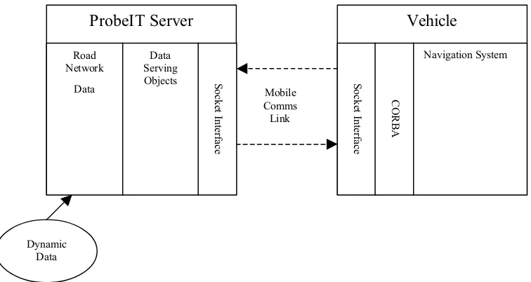
[image:3.595.106.484.521.722.2]The overall system architecture is shown in Figure 1 which indicates the three main elements of the system, the ProbeIT server, communication link and vehicle system.
Figure 1: Overall System Architecture
ProbeIT Server Vehicle
Navigation System Data Serving Objects Dynamic Data Road Network
Data Sock
The ProbeIT service uses a pair of servers working interactively at either end of a minimal bandwidth link. The ProbeIT server consists of a representation of a road network, realising the uniform data sources and the set of data serving objects the logical connection of the information, to support vehicle applications. The exchange mechanism is based on a socket interface. The central ProbeIT data server handles requests for specific data and manages a compressed binary link to a remote mobile server, which delivers the full object data across a CORBA interface to the in-vehicle components. The transferred data consists mainly of coordinates and index reference identifiers, which are typically getting to be larger and larger values as map granularity improves and attribute detail rises.
A key requirement of the system is the need to provide timely real-time data requests and response using the mobile link. The main data object is based on the principle of a 2D tile, which allows a specified region of road network data to be constructed and transferred.
To ensure that no redundant data is transferred, a number of specialised tile functions have been constructed for the ProbeIT system. These functions are: MapDrawingTile, Gazetteer, RoutingTile, BaseGeometryTile and DynamicTile. The definition of the exact format of each type of tile is specified through its object definition.
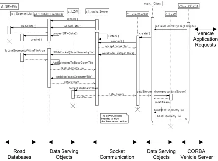
[image:4.595.71.515.379.706.2]The initial communication between the servers used CORBA, which proved to be flexible, but made it difficult to optimise the use of the bandwidth using compression algorithms. This was replaced with a direct socket to socket connection. Figure 2 illustrates the sequence of a data request for the function getBaseGeometryTile(TileSpec).
Figure 2: Sequence Diagram for Function getBaseGeometryTile(TileSpec)
Road Databases
Data Serving Objects
Socket Communication
CORBA Vehicle Server Data Serving
Objects
Vehicle Application
The initial server start-up sequence involves the creation of an index table of segments that is held in the memory. This list contains file pointer locations that allows for fast direct file access to the relevant segment information in the map database data file. This sequence is carried out at once, when the server is started. The function getBaseGeometryTile(TileSpec) requires a TileSpec object. The TileSpec object contains the bounding points for the region requested by the vehicle application. On the vehicle side this request is made to the ProbeIT CORBA server, which then passes it to the data serving objects. The object data is serialised, an LZW compression algorithm applied and the data is streamed through a socket connection to the ProbeIT data server. The TileSpec object is reconstructed at the server and passed to the data serving objects. These locate within the Segment List all segments that are contained within the TileSpec region and construct a BaseGeometryTile object containing all the segments and nodes for the specified area from the map database file. The object is serialised and streamed to the vehicle client, which then reconstructs the object and passes back through the CORBA interface to the calling application.
The Gazetteer and a number of other lookup tables for transferring dynamic data were also used, allowing simple reference values to be passed over the link reducing the quantity of data.
Most of communication relates to the request of data from the ProbeIT data server, however there is functionality for the vehicle to send ‘floating car’ data to the server. This data transfer is carried out on an exceptional basis to minimise the communication, for example if a vehicle travels a link in a slower time than expected then it could inform the server. Should a number of vehicles also report slow link times then the server could mark the link with an estimated journey time.
Data
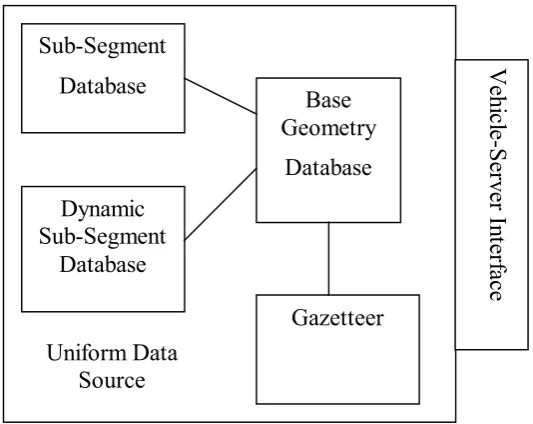
[image:5.595.166.433.469.681.2]The data structure inside the central server is made up of a number of databases, which are administered to form a unified data source, as indicated in Figure 3.
Figure 3: Server Side Application Architecture
The Base Geometry database contains the road network information derived from the map database format supplied by Navigation Technologies. The SubSegmentInfo and dynamic SubSegmentInfo databases contain additional information, such as speed limits or parking
restrictions. This will enable the vehicle to provide added information services. The dynamic SubSegmentInfo database is discussed further in the next section ‘Data Integration’.
Data Integration
One of the key elements to the ProbeIT project was to provide additional information to the vehicle. The data was primarily of two types, firstly fairly static information of an advisory nature, such as speed limits, road work information and parking restrictions. Secondly data of a more dynamic nature, potentially warning of problems on the road network such as accidents, congestion and weather problems.
To be of use, the data passing to the vehicle must be appropriate to the location and journey that is being made. The data must also arrive in a timely manner, so that action can be taken to avoid events, such as accidents or congestion. In the ProbeIT system this is achieved by relating the data to the appropriate road segment within the navigational road network data.
The data has been acquired from a number of sources:
• Roadworks information from Essex County Council. This is held in a spreadsheet
conforming to a Department for Transport (DfT) standard format.
• Traffic regulation information from Essex County Council. The Council currently use
Parkmap [3] traffic order management software for administrating their traffic regulations. This software allows the assignment of traffic order to a geological region.
• Real-time traffic information from the Highways Agency database, QMISS
(Quantified Motorway Information Supply System). QMISS [4] & [5] is part of the Travel Information Highway (TIH) project in the UK, that is promoting the exchange of live traffic data. It contains real-time recording of the Matrix Signals, Variable Message Signs and Controlled Motorway Signs for the trunk road network.
• Real-time traffic and travel information from TrafficLink [6], a third party source that
supplies information in TrafficML format.
The data is stored in the ProbeIT database in the same format, regardless of which source it comes from. A general SubSegmentInfo object was created to store the additional information. It has the following attributes:
• SegmentID, used to specify which segment the information refers to; this is
determined by the integration algorithms;
• Type and SubType, which are reference values relating to lookup tables indicating the
type of information that is been sent, e.g. speed limit;
• Side, which specifies which side of the road the information, and can be left, right or
both;
• PointOn and PointOff, which refer to the shape points of the segment and allow the
information to be restricted to just part of a segment;
• Value, which contains an integer value of the information, for example the speed limit
in miles per hour;
• QualityFactor which is an indicator of quality of information, with 100 for perfect; this
• TimeConstraint, which allows certain data such as congestion warnings to be specified
as being valid for a defined period.
The main challenge of the data integration task was determining how to obtain the SubSegmentInfo values for all the pieces of information from the data sources; specifically how to match the location to the segment in the database.
This is because each of these sources represents the location aspect of the data in a different way. The traffic regulation information was represented as regions in a graphical format using Parkmap software. The roadworks information is referenced using the WGS84 coordinates of the start and end point of the road, along with road name. In QMISS the location is referenced using a fixed point location system. TrafficLink use a WGS84 coordinate with a text-based description. The task of the data integration project was to provide an automated electronic method to analyse the data sources, map each piece of data to one or more segments and represent it in a way suitable for the ProbeIT system. The method used for each of the data sources will now be described.
Roadworks Data Source
The data for the roadwork information is held in a spreadsheet to a DfT standard format. This contains such fields as the WGS84 coordinates of start and end point of the road, the road name, a description of the roadwork and the start and end date. It also contains a text-based description of the location of the roadworks on the road, however it is not possible to use this free-text field in the matching algorithm. The only useful location information always available is the xy co-ordinates of the start and end points of the road. The roadworks information must therefore be placed into every ProbeIT segment along the road containing the roadwork.
Two methods of doing this were investigated:
• putting the information into all segments (in the vicinity of the xy coordinates) with
the same name as the roadwork road name;
• finding the shortest route from the start point to the end point of the roadwork road
and putting the information into all segments along the route.
The first method was found to be the best for several reasons. The main problems with the second method were found to be:
• the closest node to the start or finish point may not be the correct one, leading to
missed segments or extra segments or failure to find a path;
• the shortest path between the start and finish may not be the correct path of the road,
leading to the wrong road being selected;
• it might be impossible to obtain a path between nodes due to an erroneous break in the
ProbeIT data.
The steps for the roadwork matching algorithm are:
For each roadwork:
1. Get the start and finish co-ordinates and the name of the road containing the roadwork;
2. If the name contains apostrophes, remove them (see Note 1);
4. Calculate a rectangle around the roadwork with margin of 200m or 0.5*roadwork length, whichever is greater.
5. Obtain the data from the ProbeIT server for all the segments which are wholly inside the rectangle AND have the same name as the roadwork road name;
6. Put the roadwork information into these ProbeIT segments.
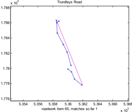
The matching process proved very successful, completely matching 371 out of the 428 roadworks, and partially matching almost all others. The unmatched roadworks were primarily due to differences in the road name between the roadwork and data sources, for example spelling differences, same road with different road name and no road names in one
source.
5.354 5.356 5.358 5.36 5.362 5.364 5.366 5.368 x 10⁵ 1.776
1.778 1.78 1.782 1.784 1.786 1.788
x 105 Trundleys Road
[image:8.595.125.349.219.411.2]roadwork item 65, matches so far 1
Figure 4 illustrates this problem where the roadwork has been only partially matched due to some road segments having different names.
5.354 5.356 5.358 5.36 5.362 5.364 5.366 5.368 x 10⁵ 1.776
1.778 1.78 1.782 1.784 1.786 1.788
x 105 Trundleys Road
roadwork item 65, matches so far 1
Figure 4: Some Segments have Wrong Name
Parkmap Data Source
[image:8.595.183.409.460.652.2]MIF file is divided into regions; each region denoting the area in which the traffic regulation is enforced and relating on a one-to-one basis with the regulation descriptions listed in the MIF file.
A road network dataset is selected for the appropriate area that covers the regions of the Parkmap data. From this the geographically relevant segments are selected that fall within each Parkmap region. The following steps are then applied.
For each region:
1. The relevant segments are selected for the region.
2. The gradients and y-intercepts for each line forming the boundary of the region are calculated.
Then for each segment and region pair:
3. The points at which the ProbeIT segment intersects each of the lines forming the boundary of the Parkmap region are calculated.
4. It is determined whether the intersection points calculated above are of interest.
5. The distances between the ProbeIT node and the intersection points and the distances between adjacent intersection points are calculated.
6. It is determined whether either of the nodes is inside the region.
7. The proportion of the ProbeIT segment inside the Parkmap region is calculated using the distances between the relevant intersection points.
8. The algorithm is repeated with the parallel lines offset by a distance of 2m from either side of the segment.
Then for final matching:
9. Every covered segment and offset is matched to the region which covers it the most.
10. A threshold value is set, (10%), this is the value beyond which the region and segment can be said to refer to approximately the same stretch of road.
11. The region is then matched to the whole segment or the forward or backward directions.
The regions describing the locations of traffic regulations in Parkmap were matched with a very high success rate to underlying road network. However, a number of complication factors were observed.
Firstly, if the region contains boundaries which are almost vertical, then rounding errors in the calculation of the gradient and y-axis intercept of the boundary can affect whether the intersection point is calculated correctly. This can mean a segment inside a region not being found, or a segment outside a region being incorrectly selected. This problem only occurs in
a very small percentage of cases.
finish point of a piece of information, but this is not currently used as the required shape points are rarely populated in the database.
Finally, if the straight line of the segment does not reflect the geometry of the Parkmap data, then there may be no overlap at all, as seen in Figure 5. This would lead to no match being made, even though the two roads are the same.
Figure 5: No Overlap between Segment and Region
QMISS Data Source
The location referencing method in the QMISS database uses a fixed point marker post ID (or PLD point), from the Point Level Database [7]. Using the PLD ID for a piece of QMISS data, information can be extracted from the PLD database. The information required for the matching algorithm includes latitude, longitude, next marker post ID, previous marker post ID and adjacent marker post ID.
The following algorithm was developed to provide a mapping between the PLD point specified in the data and the nearest segment.
For each PLD point:
1. Get the location ID, xy co-ordinates and highway reference of the PLD point. Also obtain the carriageway letter from the location ID. Also get the location IDs and coordinates of the positive and negative offsets
2. Calculate a square with a 2000m margin around the point.
3. Set a flag to show the direction of travel.
4. Set a flag to show the location of the PLD point on the carriageway.
5. Get the bearing of the motorway at the PLD point.
6. Get the relevant ProbeIT segments inside the 4000m square.
7. Get the xy coordinates, segment IDs, node IDs, directions, lengths and road names of the ProbeIT segments.
8. Put segment nodes and coordinates in order of driving direction.
9. Calculate the distance from all ProbeIT nodes to the PLD point.
10. Get the ID and coordinates of the (next) closest ProbeIT node to the PLD point.
11. Calculate the difference in bearing between the ‘PLD bearing’ and the bearing of the ‘best’ segment containing the closest ProbeIT node.
12. If the difference in bearing is more than 30° and less than 20 attempts have been made, return to step 11 and try the next closet ProbeIT node.
13. When the best segment with the correct bearing has been found, if it is at the start or end of the carriageway, accept it as the ‘matched segment’.
14. Otherwise, check whether the adjacent ProbeIT segment is a better match, accept best match as ‘matched segment’.
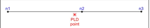
Figure 6 illustrates the importance of step 14, in ensuring that when locating the nearest segment to the PLD point that a check is made to ensure it is the best matched segment. Here node n2 is the closest ProbeIT node so segment n2-n3 would be found initially but the PLD point actually occurs in segment n1-n2.
Figure 6: Possibility of Better Match for Adjacent Segment
It was found that the algorithm matched all (or nearly all) points on the main carriageways and on short slip roads (i.e. those slip roads containing only 2 PLD points, for start and finish). Most points on long link roads between motorways (e.g. from M11 to M25) were also matched successfully.
Whilst the algorithm worked well, it was identified that it would not work under the following conditions:
• if either the start or finish location is not matched successfully;
• if no path can be found between the start and finish segments.
The matching algorithm was very successful and because of the rather static nature of the PLD, it was implemented in an off-line process. Although the location referencing is static, the information itself is dynamic and can be received through XML service from QMISS. The types of information considered for ProbeIT are: device signs, message signs, MDIS (Midlands Driver Information System), road works and traffic events. Because of the flexibility in describing types and values in sub-segment info, this type of information can be easily integrated.
TrafficML Data Source
The data from the TrafficLink source was accessed through an XML [8] file. The TrafficML format was found not to lend itself well to integration into the ProbeIT data. The problems encountered were mainly due to the imprecise and rather text oriented nature to the location data that was more suited to human readable radio broadcasting than an electronic matching procedure. Due to these reasons this data was not integrated into the ProbeIT data source.
EVALUATION
Test Scenarios
The evaluation of ProbeIT is focused on four stages that assess the system on the capabilities of the central information server, the ability to supply non-dynamic and dynamic data to the vehicle and the use of the vehicle as a source of floating vehicle information.
With these in mind, a set of test scenarios were constructed to allow the effective evaluation of the performance of the system under the full range of expected operating conditions. A number of important factors which may influence the operation of the ProbeIT system were identified and the test scenarios designed to cover the full range of combinations, allowing the capabilities and reliability of each part of the ProbeIT data chain to be assessed.
These factors were identified as occurring in three following areas:
n1 n2 n3
• Physical Factors: the type of road the vehicle is travelling on will make different
demands on the ProbeIT system. When travelling on a motorway the vehicle speed is likely to be higher, so more frequent data requests may be needed, whereas travelling slowly in a (more complex) urban area may require less frequent, but larger, sets of data from the ProbeIT data server.
• System Factors: the capacity of the mobile link may be variable, particularly in rural
areas or at peak times of the day. By testing over a range of bandwidths such as 9.6 kbps to 1Mps the change in performance can be assessed. Other factors in this group include the quantity of data pre-loaded into the vehicle cache and the different functions (such as navigation and route choice) required by the user.
• Compounding Factors: these relate mainly to the performance of the mobile
communication network which is potentially variable dependent on the time of day and different weather conditions.
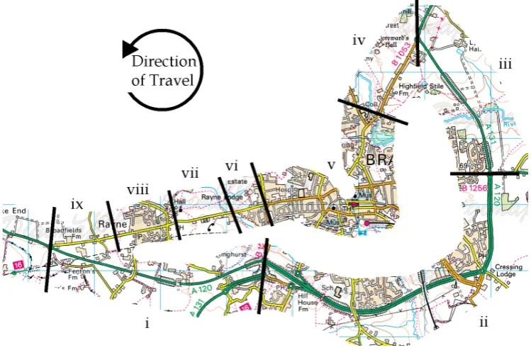
[image:12.595.110.485.287.534.2]© Crown Copyright Ordnance Survey. An EDINA Digimap / JISC supplied service.
Figure 7: Braintree Test Route
Test Routes
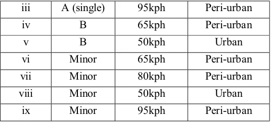
The primary test site location for the project is the 5 mile square located around the town of Braintree, Essex, UK. The main test route approaches the town from the west, before travelling along the bypass to the south of the town centre (Figure 7), providing a range of peri-urban scenarios. A return leg then travels through the town centre, providing the setting for the equivalent urban test scenarios. Table 1 shows the road type, speed limit and build environment for each of the sections along the test route.
Section Road Type Speed Limit Environment
i A (single) 95kph Peri-urban
iii A (single) 95kph Peri-urban
iv B 65kph Peri-urban
v B 50kph Urban
vi Minor 65kph Peri-urban
vii Minor 80kph Peri-urban
viii Minor 50kph Urban
[image:13.595.159.427.70.191.2]ix Minor 95kph Peri-urban
Table 1: Features of the Road Sections on the Braintree Test Route
While this test route provides settings for the urban and peri-urban physical factor combinations, there are no motorway conditions within the area. A separate test route on the M25 to the west of London was therefore identified to represent the corresponding physical factor combinations.
Evaluation Tables
Indicator tables have been created to record the results of the evaluation of each component in the ProbeIT data chain and the overall ProbeIT system. The tables are further subdivided by the type of assessment:
• Technical: where the indicator relates to a capability or functionality of the system.
• Driver: where the indicator relates to the perceptions of the end-user.
• Network Manager: where the indicator relates to the opinions of the information
provider and transport network manager.
Also, the tables include information on the method of measurement for the indicator and definitions of success where appropriate.
Results
The test runs and data collection period are scheduled for the Autumn of 2003, with analysis and formal evaluation results being determined subsequently.
FUTURE WORK
The results above show that the design and partial implementation of an integrated system to realise vehicle applications like dynamic navigation, speed advice and traffic regulation advice has been achieved within the ProbeIT project. Outstanding tasks are mainly refining the system and evaluating the approach for other vehicle applications. These aspects, together with demonstrations, are programmed for completion within the remaining timescales of the ProbeIT project.
REFERENCES
[1] UBI website: http://www.ubiubi.org.uk
[3] Parkmap website: http://www.buchanancomputing.co.uk/parkmap.htm
[4] QMISS website: http://www.qmiss.org.uk
[5] QMISS Specification: QMISS - VASP Interface Design Document Version 3.0,
Mott MacDonald, November 1999.
[6] TrafficLink website: http://www.trafficlink.co.uk/
[7] PLD Specification: Point Level Database Structure, Content and Validation,
Owen Williams Consultancy (for HA Traffic Systems and Signing), April 2001.
[8] TrafficML Specification: TrafficML Version 2.0 Specification,