OCTOBER 1965
TECHNICAL MANUAL
FDR
TM-~~
TAPE TRANSPDRT
AMPEX
CDMPUTER PRDDUCTS DIVISIDNP.D. BDX 329, CULVBA CITY, CALIF.
3110278-10
LIST DF EFFECTIVE PABES
All pages are original through revision D, except for page 5-24, which is a revision E page.
TABLE OF CDNTENTS
Section Paragraph
I GENERAL DESCRIPTION
1-1 1-2 1-3 1-4 1-5 1-6 1-7 1-8 1-9 1-10 1-11 1-12 1-13 1-14 1-15 1-16 1-17 1-18 1-19 1-20 1-21 1-22 1-23 1-24
Scope . . . . General Description . . . . Performance Characteristics
Major Assemblies . . . . Autotransformer Assembly .. . Cabinet Blower Assembly . . . . Cable Assemblies . . . . Capstan Servo Assembly . . . . . Control Electronics Assembly . . . . Data Electronics Assembly (Option). Electronics Frame . . . .
Enclosures . . . . . . .
Input/Output Panel . . . .
Logic Power Supply . . . .
Operator Control Panel . . . . Reel Servo Assembly . . . . Tape Deck . . . . Magnetic Head Assembly . . . . Photosense Assembly . . . .
Reel Retainers . . . . Tape Cleaners . . . . Write Enable Switch Assembly . . . . Vacuum Blower Housing Assembly . . . . Vacuum Control Assembly . . . .
II INSTALLATION
2-1 2-2 2-3 2-4 2-5 2-6 2-7 2-8 2-9 2-10 2-11
Introduction . . . .
General . . . .
Custom Installations . . . . Unpacking . . . . Physical DimensioRs and Weights . . . . Power Requirements. . . .
Input/Output Signals and Connections. . . . . . .
Input/Output Connectors . . . . Command Signals . . . .
Select. . . . . . .
Forward/Reverse,. . . ., . . . .
Section Paragraph
II 2-12 Run/Stop . . . " .. . . . .. . . . .. 2-13
2-13 Forward/Stop . . . ... . . ',' . . . .. 2 -13
2-14 Reverse/Stop . . . '. . .. . . . .. 2-13
2-15 Rewind. . . • . . . .. 2-13
2-16 Rewind and Lockout . . . .. 2-13
2-17 High/Low Density Select. . . • . . .. 2-13
2-18 Status Signals . . . ' . . . . ~ . . . ; . . . .. 2-13
2-19 Ready. .. . . . .. 2-14 2-20 Unit Select . . . .. 2-14
2-21 Select and Remote Indicator. .. . . . .2-14
2-22 Beginning-of-Tape . . . .. 2-14
2-23 End-of-Tape . . . .. 2-14
2-24 Rewinding . . . '. . . .. 2-14
2-25 High/Low Density. . . .. 2-14
2-26 Write Enable Status . . . .. . . . .. 2-14
2-27 Data Signals ' . . • . ~: . . . .. 2-14
2-28 Write Data . . . ' . . . .. 2-15
2-29 Read Data. . . .. 2-15
2-30 Environment . . . .. 2 -15
2-31 Operating Environment. . . .. 2-15
2-32 Storage and Shipping Environment. . . .. 2-15
III OPERATION
3-1 Introduction. . . 3-1
3-2 Operator Control Panel Controls and Indicators. . . .. 3-1
3 -3 POWER Switch. . . . . . 3-1
3-4 FILE PROTECT Indicator. . . • . . . .. 3-1
3-5 REMOTE Switch. . . .. 3-1
3-6 LOCAL Switch . . . , . . . .. 3-1
3-7 HIGH/LOW DENSITY Switch .. ; . . . ' . . . 3-1
3 .... 8 FORWARD Switch. . . .. 3-3
3-9 REVERSE Switch. . . .. . .. . . . .. 3-3
3-10 REWIND Switch. . . .. 3-3
3-11 STOP Switch . . . • . . . • . . . . ' . . . ' 3-3
3-12 Tape Load and Door Interlock Override Switches. . .. . . . . .. 3-3
3 -13 TAPE LOAD Switch. . . .. 3-3
3-14 DOOR INTERLOCK OVERRIDE Switch. . . .. 3-3
3-15 Interlocks. . . .. 3-3
3-16 Power On .' . • . . . • . . . '. . . .. 3-4
3-17 POWER ',Off . . . ,' . . . '. .. .. 3-4
3-18 ReelAccess Door . . . 3-4
3-19 Vacuum Failure. .. .. . . . .. 3-4
3-20 Photosense Tab Control. • . • . . . .. 3-4
Section Paragraph
IV THE OR Y OF OPERATION
4-1 4-2 4-3 4-4 4-5 4-6 4-7 4-8
4-9
4-10 4-11 4-12 4-13 4-14 4-15 4-16 4-17 4-184-19
4-20 4-21 4-22 4-23 4-24 4-25 4-26 4-27 4-284-29
4-30 4-31 4-32 4-33 4-34 4-35 4-36 4-37 4-38 4-39 4-40Scope. . . .. . . . . .
Capstan Servo System. . . . . . .
Capstan Motor and Capstan . . . . . . .
Capstan Servo Control. . . . . . .
Capstan Servo System Operation . . . . Steady-State Operation . . . . Power Amplifier . . . . Acceleration Control . . . . High Speed Control . . . . Reel Servo System .. . . . . Tape Reel and Reel Motor . . . . Reel Servo Control . . . . Tape Loop Position Sensing . . . . Reel Tachometer and Pulley. . . . Reel Servo System Operation . . . . Forward Operation, Tape Initially at Rest . . . . Reverse Operation . . . . Forward to Reverse Operation . . . . Reverse to Forward Operation . . . . Null Detector Circuit . . . . Reel Brake Operation . . . . Tape Loop Positioning . . . . Tape Tension . . . . Vacuum Buffer Storage . . . . Vacuum Pressure Control . . . . Control Electronics . . . .
Printed Circuit Board (PCB) Assemblies . . . . Write Enable Switch Assembly . . . . Photosense Head. . . . Power On Sequencing . . . .
Local Mode Operation . . . . . Forward . . . . Reverse . . . .
Stop . . . . Rewind . . . .
Density Control. . . . Remote Mode Operation . . . .
Forward and Reverse (RUN/STOP
and FWD/REV Inputs) . . . .. . . . . Forward and Reverse (FWD/STOP
and REV/STOP Inputs) . . . . Stop . . . ' . . . .
Sec tion Paragra ph
IV
4-41
4-42
4-43
4-44
Rewind . . . . Rewind and Lockout .. Density Select Output . Read/Write Head Assembly.
V MAINTENANCE
5-1
5-2
5-3
5-4
5-5
5-6
5-7
5-8
5-9
5-10
5-115:-12
5-13
5-14
5-15
5-16
5-17
5-18
5-19
5-20
5-21
5-22
5-23
5-24
5-25
5-26
5-27
5-28
5-29
5-30
5-31
5-32
5-33
5-34
5-35General . . . .
Preventive Maintenance . . . . Cleaning the Tape beck . . . . Cleaning the Tape Cleaner. . . . Cleaning the Cabinet. . . . Cleaning the Positive-Pressure Filter . . . . Cleaning the Capstan-Motor Filter Screen . . . . Removal and Replacement Procedures . . . . Upper Overlay Plate Removal and Replacement . . . . Capstan-Motor and Capstan Removal and Replacement . . . . Read/Write Head Removal and Replacement . . . . Photosense Head Removal and Replacement . . . . Reel Retainer Removal and Replacement . . . . Reel Motor Assembly Removal and Replacement . . . . Reel Motor Brake and Brake Lining
Removal and Replacement . . . .. . . . . Vacuum Chamber Removal and Replacement . . . . Checking Reel Motor and Replacement of Brushes . . . . Vacuum -Blower Unit and Motor Brush
Removal and Replacement . . . . Reel Tachometer Assembly Removal and Replacement . . . . Reel Acce ss Door Removal and Replacement. . . . Write-Enable Switch Assembly, Removal and Replacement . . . Adjustments . . . .
Vacuum Adjustment . . . ~ . . . .
Logic Power Supply Adjustments . . . . Reel Brake Air -Gap Adjustment . . . . Positive-Pressure Adjustments . . . . Capstan Servo System Adjustments . . . . Reel Servo System Adjustments . . . .
Preliminary Adjustments . . . ' . . . .
Final Adjustments . . . . Photosense Threshold Adjustment . . . ' . . . . Write-Enable Switch Assembly Adjustment . . . . Checking Operational Parameters . . . . Start- and Stop..;Time Checkout. . . . . Start Time Definition . . . .
Section Paragraph
v
5-36
5-37
5-38
5-39
5-40
Stop Time Definition . . . . Checkout Procedure . . . . Interchannel Time Displacement
Error (ITDE) Checkout . . . . . Photosense Checkout . . . . Tools and Test Equipment
VI CIRCUIT DESCRIPTIONS
6-1 Introduction.
VII DRAWING S
Figure 1-1 2-1
3-1
3-2 4-1 4-24-3
4-4 4-5 4-6 4-7 4-8 4-9 4-105-1
5-2 5-3 5-47-1 Introduction.
LIST DF ILLUSTRATIONS
Title
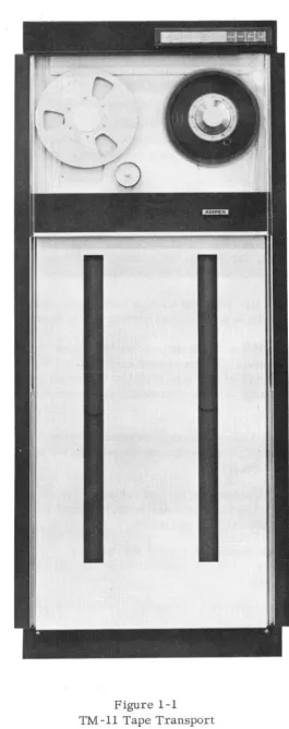
TM -11 Tape Transport .
Input/Output Panel . . . .
Tape Transport Controls, Indicators, and Tape Loading Path . . . .
Reflective Tab Placement Diagram . . . . . . .
Tape Drive, Flow Diagram . . . . Capstan Servo System, Flow Diagram . . . .
Tape Drive Path and Reel Servo Sensors. . . . .. . . . . Reel Servo Control, Input and Preamplifier Flow Diagram. Reel Servo Control, Driver and Output Flow Diagram .. File Reel Forward Drive, Simplified Schmitt
Trigger Control Voltage Diagram . . . . File Reel Forward to Reverse Drive, Simplified
Schmitt Trigger Control Voltage Diagram . . . . Motor-Speed Control, Block Diagram . . . .
Motor-Speed Control, Waveforms. . . . . .
TM -11 Interlock Circuits. . . . . . .
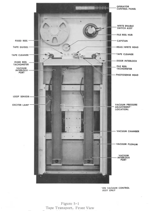
Tape Transport, Front View . . .. . . . . .
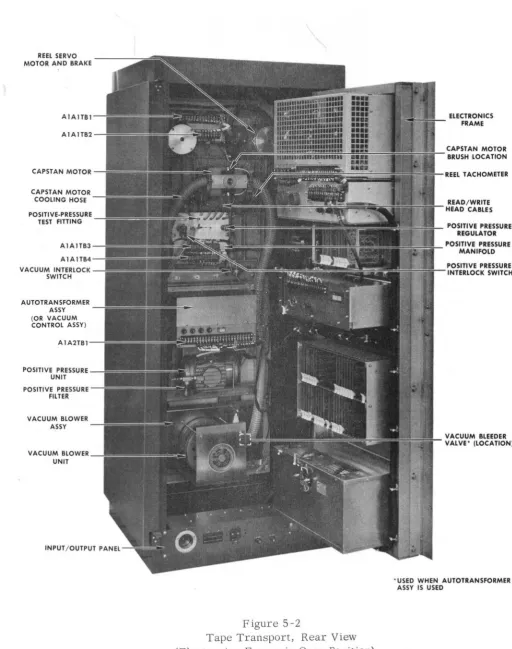
Tape Transport, Rear View. . . . . . .
Tape Transport Electronics Frame, Front View. . . . . . .
Reel Motor Brake, Exploded View.. .. . . . .
Figure
5-5
5-6
5-7
5-8
5-9
5-10
5-11 5-12
5-13
Table
1-1
2-1
2-2
2-3
2-4
2-5
2-6 2-7
4-1
5-1
5-2
5-3
5-4
5-5
Title
Vacuum -Blower Unit . . . .
Control Electronics Assembly and Logic Power Supply . . . . . . .
Capstan Servo System, Flow Diagram . . . . Tape Drive Adjustment, Equipment Connection . . . . Read Amplifier Output Waveforms, Capstan Servo Adjustment . . . . Start- and Stop-Time Measurement,. Test Setup . . . . Start- and Stop-Time Measurement, Wave shape . . . . Interchannel Time Displacement Error, Test Setup . . . .
Interchannel Time Displacement Error, Typical Waveshape . . . .
LIST DF TABLES
Title
TM -11 Tape Transport Performance Characteristics
Reference Designation Numbers of Assemblies. . . . . . .
Physical Dimensions and Weights . : . . . . . . .
Control Connections (Transport Without Data Electronics) . . . . Data Input Connections (Transport Without Data Electronics) . . . . . Local Control Connections . . . . Typical Input Connections (Transport With Data Electronics) . . . . Typical Output Connections (Transport With Data Electronics) . . . .
Printed Circuit Board Cross -Reference List . . . .
Schedule of Preventive Maintenance . . . Vacuum V s Line Voltage . . . . Frequency Vs Tape Speed . . . . Capstan RPM V s Tape Speed . . . . Suggested Tools . . . .
5-15
5-20
5-23
5-24
5-28.
5-34
5-34
5-35
5-35
1-3
2-2
2-3
2-6 2-7
2-8
2-11
2-12
4-22
5-5
5-19
5-25 5-26
1-1. SCOPE.
SECTIDN I
GENERAL DESCRIPTIDN
This technical manual describes the installation, operation, theory of operation, and maintenance of the Ampex TM -11 Tape Transport. (See Figure 1-1.) Section I includes a general description of the equipment and lists performance characteristics.
1-2. GENERAL DESCRIPTION.
The tape transport moves computer grade magnetic tape across a dual-stack magnetic read/write head assembly, in response to commands from either an operator control panel or from remote equipment. Tape is moved in either the forward or reverse direction, or held at a standstill by a servo-controlled direct-drive capstan.
The capstan draws tape from the storage loops in the vacuum chambers. The reel
motors are servo -controlled to maintain the correct supply of tape within the chambers.
The tape is held in contact with the capstan by uniform tension derived from the vacuum columns. The vacuum columns remain active during the rewind operation to provide the tension required to ensure proper tape packing. Precision air-lubricated tape guides ensure accurate tape tracking; a positive pressure system provides the lubricating air-flow to the tape guides.
. . '" .
The read/write head assembly reads information from the tape (to external equipment or the optional data electronics) and writes information on the tape (from external equipment or the optional data electronics).
A two -channel photosense head detects reflective markers fixed to the tape. The photo-sense signals are amplified and are provided to the transport control electronics, the data electronics (option), and the external equipment.
Electro -mechanical interlocks protect the operator, the tape, and the equipment in
the event of failure . . Programming·is inhibited while the equipment stabilizes and the vacuum
and positive pressures build up.
The optional data electronics is described in the Data Electronics Technical Manual.
1-3. PERFORMANCE CHARACTERISTICS.
Figure 1-1
[image:10.607.148.413.53.721.2]TABLE 1-1
TM-11 TAPE TRANSPORT PERFORMANCE CHARACTERISTICS
TAPE WIDTH 1/2 inch tape
Ampex, IBM, or NAB reels
TAPE SPEEDS 120 ips standard
75 and 112.5 ips optional
REWIND SPEED 2400 ft in less than 100 seconds
START/STOP TIME 120 ips: 3.8 ms
112.5 ips: 4.0 ms 75 ips: 6.0 ms
START DISTANCE 0.225 inch nominal
STOP DISTANCE O. 225 inch nominal
LONG TERM SPEED VARIATION ±3% or less of operational speed
INSTANTANEOUS SPEED VARIATION ISV
=
±3% or less of operational speedSHORT TERM 10 ms after start command
INTERCHANNEL TIME DISPLACEMENT 120 ips: 4.11 flsec max
(STATIC SKEW
+
1/2 DYNAMIC SKEW) 112.5 ips: 4.40 flsec max75 ips: 6.56 flsec max
STATIC SKEW (MAX) 120 ips
=
3.36 flsec112.5 ips
=
3.60 flsec75 ips
=
5.36 flsecDYNAMIC SKEW (P - P) 120 ips
=
1. 5 flsec112.5 ips
=
1. 6 flsec75 ips
=
2.4 flsecPOWER REQUIREMENTS Voltage: 115 VAC nominal (standard)
1-4. MAJOR ASSEMBLIES.
The major assemblies of the TM -11 Tape Transport are the cabinet blower assembly, the cable assemblies, the capstan servo assembly, the control electronics assembly, the optional data electronics, the electronics frame, the enclosure, the input/output panel, the logic power supply, the optional operator control panel, the reel servo assembly, the tape deck, the vacuum blower housing assembly, and either the vacuum control assembly or the autotransformer assembly.
1-5. AUTOTRANSFORMER ASSEMBLY.
The autotransformer assembly contains an autotransformer, a compressor unit, and two relays. The autotransformer provides operating power for the vacuum -blower motor; taps on the autotransformer provide for discrete adjustment of the tape -transport vacuum pressure by changing the voltage supplied to the vacuum-blower motor. The compressor unit provides the positive pressure used at the air-lubricated tape guides, the
write-enable-switch assembly, and the magnetic head tape gate. One of the relays is used in the tape load
circuit, the other is used in the door-interlock override circuit.
1-6. CABINET BLOWER ASSEMBLY.
The cabinet blower assembly provides cooling for the tape transport.
1-7. CABLE ASSEMBLIES.
Cable and harness assemblies are determined by transport mounting and by selection of optional features.
1-8. CAPSTAN SERVO ASSEMBLY.
The capstan servo assembly provides power for the capstan motor and contains the power components of the capstan servo system. Field excitation for electromagnetic-field capstan motors is provided by a field supply furnished in the capstan servo assembly when such motors are used ..
1-9. CONTROL ELECTRONICS ASSEMBLY.
1-10. DATA ELECTRONICS ASSEMBLY (OPTION).
The data electronics assembly contains the printed circuit board assemblies which control the writing and reading of data on the tape passing over the magnetic head assembly. The data electronics is an optional feature.
1-11. ELECTRONICS FRAME.
The electronics frame mounts into a standard 24-inch rack-type mount or into the TM-ll console cabinet. The capstan servo assembly, the reel servo assembly, the control electronics assembly, the logic power supply, the optional data electronics, and the cabinet blower assembly are mounted on the electronics frame. The frame is hinged and provides access to the console cabinet and to the assemblies mounted on the frame.
1-12. ENCLOSURES.
The TM-11 Tape Transport is designed for vertical installation in a standard 24-inch rack -type mount or for installation in the Ampex TM -11 console cabinet.
1-13. INPUT/OUTPUT PANEL.
The input/output panel provides receptacles for AC power input and distribution and for remote input and output lines. A circuit breaker on the panel provides overload
protec-tiori for the AC power input to the tape transport. The panel also contains two AC convenience
receptacles, which are connected directly to the AC power input. A fuse on the panel provides overload protection for the convenience receptacles. A second fuse on the panel provides overload protection for a voltage step-down transformer mounted on the input/output panel. The transformer supplies operating power for the control relay on the panel. The relay is used in the power on -off control circuit.
1-14. LOGIC POWER SUPPLY.
The logic power supply provides +24V and -24V unregulated DC voltages and +12V, -12V, and -6V regulated DC voltages for the control electronics PCB assemblies and for the optional data electronics.
1-15. OPERATOR CONTROL PANEL.
1-16. REEL SERVO ASSEMBLY.
The reel servo assembly provides power for the reel motors and reel brakes, and
power for all 12 ~volt DC relays used in the tapetransport.
1-17 . TAPE DECK.
The tape deck consists of all tape drive components mounted on a web-reinforced precision casting. A plenum is molded into the casting, and with the addition of a ported cover plate, serves as the positive-pressure manifold for the tape deck. Also mounted on the tape deck are the tape cleaners and the photosense, magnetic head, reel hub, and write -enable -switch assemblies.
1-18. Magnetic Head Assembly. The standard magnetic head assembly is either a 7-track
dual-stack read/write unit capable of reading and writing in IBM compatible format, or a 9-track unit capable of reading and writing in ASCII compatible format. An erase head is supplied as an optional feature.
1-19. Photosense Assembly. The photosense assembly provides IBM compatible BOT
(beginning-of-tape; at load point) and EOT (end-of-tape) photosensing of reflective tabs on the back of the tape.
1-20. Reel Retainers. Reel retainers are a selective feature. IBM or NAB compatible
screw -down reel retainers may be selected for either the fixed or the file reel. The fixed reel may be a permanently-mounted precision reel assembly.
1-21. Tape Cleaners. The tape cleaners provide for collection of shed materials from the
oxide surface of the magnetic tape. A low-velocity air-flow through the tape cleaners deposits these particles in the vacuum -blower -housing plenum.
1-22. Write Enable Switch Assembly. A write enable switch assembly is provided for
either the IBM or the NAB compatible file reel.
1-23. VACUUM BLOWER HOUSING ASSEMBLY.
1-24.
VACUUM CONTROL ASSEMBLY.The vacuum control assembly contains the vacuum-blower-motor speed control circuit, a compressor unit, and two relays. The vacuum -blower -motor speed control cir-cuit provides operating power for the vacuum -blower motor and maintains a preset motor speed, independent of line voltage fluctuations and minor load changes. The compressor unit provides the positive pressure used at the air-lubricated tape guides, the
2-1. INTRODUCTION.
SECTIDN II
INSTALLATIDN
This section provides information for the installation of the tape transport.
2-2. GENERAL.
The TM-ll Tape Transport is designed for installation in the Ampex TM-ll
cabinet or in a standard 24 -inch rack -type enclosure.
The TM -11 Cable Diagram in Section VII is the interconnecting cabling diagram for the basic transport. When the data electronics option is taken, the TM-11211 Cable Diagram in Section VII is used as the interconnecting cabling diagram.
2-3. CUSTOM INSTALLATIONS.
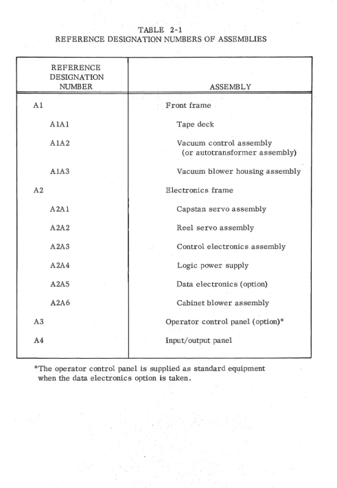
Tape reels and overlay panels must be removed to install mounting screws for standard 24-inch rack-type tape transport installation. Table 2-1 lists the assemblies by reference designation number. See the applicable TM -11 cable diagram in Section VII for a ssembly locations.
2-4. UNPACKING.
Custom-built crates are designed for shipping Ampex equipment. When an
en-closure is supplied with the equipment, the components are installed in the cabinet and are
ready for installation and operation. When no cabinet is supplied, custom shipping crates are provided for the com ponents .
Care should be exercised during unpacking and the equipment should be checked for shipping damage prior to application of power.
The input/output panel is installed with spacers to recess the front of the panel from the mounting frame during shipment. These spacers must be removed when the tape transport is installed.
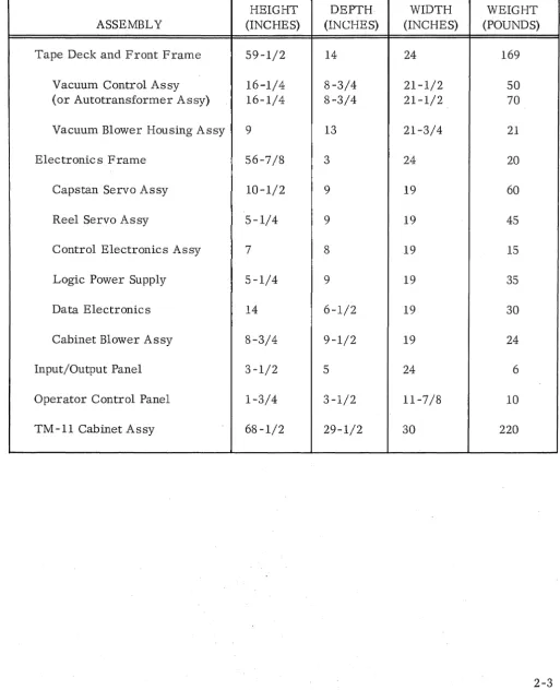
2-5. PHYSICAL DIMENSIONS AND WEIGHTS.
TABLE 2-1
REFERENCE DESIGNATION NUMBERS OF ASSEMBLIES
REFERENCE DESIGNATION
NUMBER ASSEMBLY
Al Front frame
AlAI Tape deck
AlA2 Vacuum control assembly
(or autotransformer assembly)
AIA3 Vacuum blower housing assembly
A2 Electronics frame
A2Al Capstan servo assembly
A2A2 Reel servo assembly
A2A3 Control electronics assembly
A2A4 Logic power supply
A2A5 Data electronics (option)
A2A6 Cabinet blower assembly
A3 Operator control panel (option)*
A4 Input/output panel
[image:17.615.67.559.37.748.2]TABLE 2-2
PHYSICAL DIMENSIONS AND WEIGHTS
HEIGHT DEPTH WIDTH WEIGHT
ASSEMBLY (INCHES) (INCHES) (INCHES) (POUNDS)
Tape Deck and Front Frame 59-1/2 14 24 169
Vacuum Control Assy 16-1/4 8-3/4 21-1/2 50
(or Autotransformer Assy) 16-1/4 8-3/4 21-1/2 70
Vacuum Blower Housing Assy 9 13 21-3/4 21
Electronics Frame 56-7/8 3 24 20
Capstan Servo Assy 10-1/2 9 19 60
Reel Servo Assy 5-1/4 9 19 45
Control Electronics Assy 7 8 19 15
Logic Power Supply 5-1/4 9 19 35
Data Electronics 14 6-1/2 19 30
Cabinet Blower Assy 8-3/4 9-1/2 19 24
Input/Output Panel 3-1/2 5 24 6
Operator Control Panel 1-3/4 3-1/2 11-7/8 10
[image:18.615.62.575.134.765.2]2-6. POWER REQUIREMENTS.
The TM-11 Tape Transport is wired for 115 volt operation unless otherwise speci-fied. Maximum operating current at 115 VAC is 24 amperes. Tapped transformers in the vacuum control assembly (or the autotransformer assembly), the servo assemblies, the input/ output panel, and the logic power supply provide for operation with either 115 ±ll. 5 VAC or 230 ±23 VAC input voltage. AC input power is applied at J 1 on the input/output panel. (See Figure 2-1.)
2-7. INPUT/OUTPUT SIGNALS AND CONNECTIONS.
The input/output signals to the tape transport consist of remote control command and status signals and read/write data signals. Connector J4 on the Ampex input/output panel (Figure 2-1) provides connections for the customer-furnished transport control cable used for the command and status signals. Table 2 -3 lists the command and status signals and pin des ignations for the connector. Connector J5 on the input/ output panel pro-vides the connections for the read -data output signals and the write -data input signals. This
connector also provides the connections for the optional erase signal. Table 2 -:4 lists the
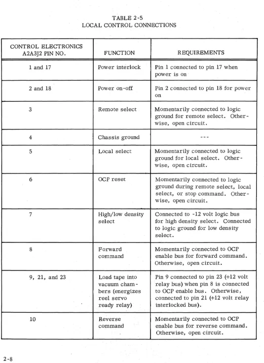
read - and write -data pin designations and the erase -signal pin designations for the connector. If the operator control panel is not supplied, equivalent controls should be provided for local control during tape changes and maintenance. Connector J2 on the control electronics
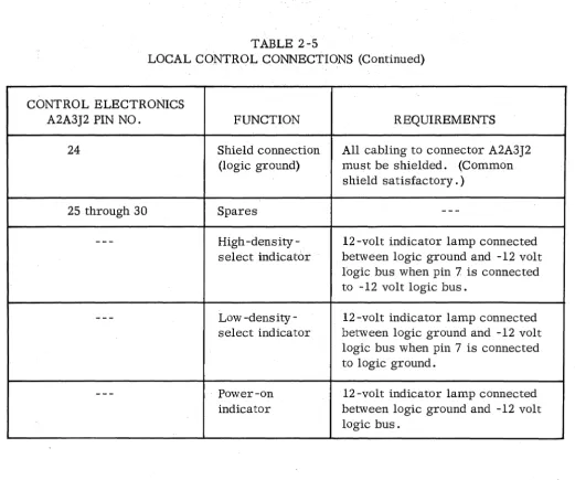
assembly provides connections for a customer -furnished operator -control-panel equivalent; the signal requirements and pin designations are listed in Table 2 -5 . Refer to Section III for the description of the operator control panel functions.
When the data electronics option is taken, connector J4 on the input/output panel provides connections for all input signals from the customer to the tape transport.
Connector J5 on the input/output panel provides connections for all output signals from the tape transport to the customer. These input and output signals are described in the Data Electronics Technical Manual. Table 2 -6 herein lists input signals and pin designations for connector J4. Table 2-7 lists output signals and pin designations for connector J5.
2 -8. INPUT /OUTPUT CONNECTORS.
Mating connectors for customer fabricated cables are provided. (See Figure 2 -1.)
2 -9. COMMAND SIGNALS.
Command signals to the tape transport control electronics must fulfill the following requirements. The FALSE level must be 0 ±1.25 volts. The TRUE level may be -10 to
MATING CONNECTOR
FOR A4Jl
MATING CONNECTOR
FOR A4J5
MATING CONNECTOR
FOR A4J4
TABLE 2-3
CONTROL CONNECTIONS (TRANSPORT WITHOUT DATA ELECTRONICS)
INPUT -OUTPUT PANEL
A4J4 PIN NO. SIGNAL DESCRIPTION TYPE
A REWINDING STATUS (-) STATUS
B READY STATUS (-) STATUS
C HIGH/LOW DENSITY STATUS (-/+) STATUS
D SELECT (-) COMMAND
E UNIT SELECT (-) STATUS
F SELECT AND REMOTE INDICATOR (+) STATUS
H HIGH/LOW DENSITY SELECT (-/+) COMMAND
(OUTPUT)
J REWIND COMMAND (-) COMMAND
K REWIND AND LOCKOUT (-) COMMAND
L GROUND
--M BEGINNING -OF -TAPE (-) STATUS
N END-OF-TAPE (-) STATUS
P GROUND
--R FORWARD/REVERSE (-/+)* COMMAND
S RUN/STOP (-/+)** COMMAND
T GROUND
--U WRITE ENABLE STATUS (NC) STATUS
V ,I WRITE ENABLE STATUS (C) STATUS
.1
W WRITE ENABLE STATUS (NO) STATUS
X SHIELD
TABLE 2-4
DATA INPUT CONNECTIONS (TRANSPORT WITHOUT DATA ELECTRONICS)
INPUT/OUTPUT PANEL
A4J5 PIN NO. SIGNAL DESCRIPTION
A Write Data 1 Return
B . W rite Data 2 Return
C Write Data 1
D Write Data 2
E Write Data 3
F Write Data 4
G Write Data 5
H Write Data 6
J Erase Head
K Erase Head Return
L Write Head Ground (Grd Lug)
M W rite Head Center Tape (Option)
N Write Data 9 Return
P Write Data 8
R W rite Data 3 Return
S Write Data 8 Return
T W rite Data 4 Return
U Write Data 5 Return
V W rite Data 6 Return
W Write Data 7 Return
y Write Data 6
Z Write Data 7
a Read Data 1
b Read Data 2
c Read Data 1 Return
d Write Cable Common Shield
e Read Data 4
f Read Data 3
g Read Data 4 Return
h Read Data 5
j Read Data 6
k Read Data 2 Return
1 Read Data 7
m Read Data 8
n Read Data 7 Return
p Read Data 8 Return
r Read Data 9
s Read Data 5 Return
t Read Cable Common Shield
u Read Data 3 Return
v Read Data 9 Return
w
Read Head Ground [image:22.612.71.547.103.754.2]TABLE 2-5
LOCAL CONTROL CONNECTIONS
CONTROL ELECTRONICS
A2A3J2 PIN NO. FUNCTION REQUIREMENTS
1 and 17 Power interlock Pin 1 connected to pin 17 when
power is on
2 and 18 Power on -off Pin 2 connected to pin 18 for power
on
3 Remote select Momentarily connected to logic
ground for remote select. Other-wise, open circuit.
4 Chassis ground
-
--5 Local select Momentarily connected to logic
ground for local select. Other-wise, open circuit.
6 OCP reset Momentarily connected to logic
ground during remote select, local select, or stop command. Other-wise, open circuit.
7 High/low density Connected to -12 volt logic bus
select for high density select. Connected
to logic ground for low density select.
8 Forward Momentarily connected to OCP
command enable bus for forward command.
Otherwise, open circuit.
9, 21, and 23 Load tape into Pin 9 connected to pin 23 (+12 volt
vacuum cham- relay bus) when pin 8 is connected
bers (energizes to OCP enable bus. Otherwise,
reel servo connected to pin 21 (+12 volt relay
ready relay) interlocked bus).
10 Reverse Momentarily connected to OCP
command enable bus for reverse command .
[image:23.615.39.560.46.760.2]TABLE 2-5
LOCAL CONTROL CONNECTIONS (Continued)
CONTROL ELECTRONICS
A2A3J2 PIN NO. FUNCTION REQUIREMENTS
11 Rewind command Momentarily connected to OCP
enable bus for rewind command. Otherwise, open circuit.
12 Stop command Momentarily connected to logic
ground for stop command. Other-wise, open circuit.
13 Drives select- 12 -volt indicator lamp connected
and -remote between pin 13 and -12 volt logic
indicator lamp bus.
14 Drives local 12 -volt indicator lamp connected
indicator lamp between pin 14 and -12 volt logic
bus.
15 Drives remote 12 -volt indicator lamp connected
indicator lamp between pin 15 and -12 volt logic
bus.
16 Drives file pro- 12 -volt indicator lamp connected
tect indicator between pin 16 and -12 volt logic
lamp bus.
17 Refer to pin 1
18 Refer to pin 2
19 -12 Volt logic bus
--
-20 Logic ground
---21 Refer to pin 9
22 OCP enable bus
TABLE 2-5
LOCAL CONTROL CONNECTIONS (Continued)
CONTROL ELECTRONICS
A2A3J2 PIN NO. FUNCTION REQUIREMENTS
24 Shield connection All cabling to connector A2A3J2
(logic ground) must be shielded. (Common
shield satisfactory.)
25 through 30 Spares
-
---
High -density- 12 -volt indicator lamp connectedselect indicator between logic ground and -12 volt
logic bus when pin 7 is connected to -12 volt logic bus.
-
--
Low -density- 12 -volt indicator lamp connectedselect indicator between logic ground and -12 volt
logic bus when pin 7 is connected to logic ground.
---
Power-on 12-volt indicator lamp connectedindicator between logic ground and -12 volt
logic bus.
2-10. Select. When FALSE, the select line disables tape motion inputs to the control electronics and also disables status outputs from the control electronics. A select TRUE level will enable the remote inputs if the transport is in the ready and remote status.
Transport ready requires that all interlocks are closed. Remote is TRUE when the REMOTE pushbutton, on the operator control panel, has been pressed.
2-11. Forward/Reverse. * When TRUE, forward direction is selected. When FALSE, reverse direction is selected. The forward/reverse level must be established 5 usec prior to a RUN command. A change in level on this line, while the tape is in motion, will cause the tape to stop.
[image:25.615.36.557.41.475.2]TABLE 2-6
TYPICAL INPUT CONNECTIONS (TRANSPORT WITf-I DATA ELECTRONICS
INPUT /OUTPUT PANEL A4J4
PIN NO. SIGNAL DESCRIPTION
A Ground
B Ground
C Write Data 1 (-)
D Write Data 2 (-)
E Write Data 3 (-)
F Write Data 4 (-)
G Spare
H Ground
J Ground
K Ground
L Ground
M Write Data 5 (-)
N Write Data 6 (-)
P Write Data 7 (-)
R Write Data 8 (-)
S Write Data 9 (-)
T Ground
U Ground
V Ground
W WRITE STROBE (-)
X WRITE RESET (-)
Y RUN/STOP (-/+)*
z
REWIND and LOCKOUT (-)a Ground
b Ground
c WRITE PERMIT (-)
d READ PERMIT (-)
e FORWARD /REVERSE (- /+)**
f REWIND COMMAND (-)
g Ground
h Ground
j Spare
k Spare
1 ODD/EVEN PARITY (-/+)
m Shield Ground
*FORWARD/STOP (-/+) when Fwd/Stop-Rev/Stop logic is supplied.
[image:26.615.99.538.86.669.2]TABLE 2-7
TYPICAL OUTPUT CONNECTIONS (TRANSPORT WITH DATA ELECTRONICS)
INPUT /OUTPUT
PANEL A4JS1
PIN NO. SIGNAL DESIGNATION
A Ground
B Ground
C Read Data 1 (-)
D Read Data 2 (-)
E Read Data 3 (-)
F Read Data 4 (-)
G Read Data 8 (-)
H Ground
J
GroundK Ground
L Ground
M Read Data S (-)
N Read Data 6 (-)
P Read Data 7 (-)
R READ CLOCK (-)
S Ground
T Ground
U Ground
V WRITE ENABLE STATUS (C)
W BEGINNING -OF -TAPE (-)
X END-OF-TAPE (-)
Y REWINDING STATUS (-)
Z READY STATUS (-)
a WRITE ENABLE STATUS (NO)
b WRITE ENABLE STATUS (NC)
,
c WRITE CHECK ERROR (-)
d Ground
e HIGH!LOWDENSITY STATUS (-/+)
f Read Data 9 (-)
g Ground·
h PARITY ERROR(-)
j Spare
k UNIT SELECT (-)
1 SELECT AND REMOTE INDICATOR (+)
2-12. Run/Stop. * A transition to the TRUE level will cause the capstan to move the tape. The direction of the tape motion is determined by the previously established forward/ reverse line. A FALSE level will cause tape motion to stop.
2-13. Forward/Stop~* A transition to the TRUE level on the forward/stop line will cause
the capstan to move the tape in the forward direction. A change in level on this line, while the tape is in motion, will cause the tape to stop.
2-14. Reverse/Stop'!'* A transition to the TRUE level on the reverse/stop line will cause
the capstan to move the tape in the reverse direction. A change i~ level on this line, while
the tape is in motion, will cause the tape to stop.
2-15. Rewind. A TRUE level will initiate a high speed rewind cycle. The tape will rewind
to the BOT photosense tab and the capstan will place the tape at the load pOint. The
trans-port will remain in remote mode. High speed in the forward direction can be provided as an optional feature.
2 -16. Rewind and Lockout. A TRUE level will initiate a high speed rewind cycle and return the transport to local mode. The tape will rewind to the BOT photosense tab and the capstan will place the tape at the load point. Unloading of tape from the BOT tab is done manually after operating the TAPE LOAD switch.
2-17. High/Low Density Select. This line is a command output from the operator control panel. The line is used to select the bit-packing density when the data electronics option is taken. When high-density packing is selected the line is at the TRUE level. When low-density packing is selected the line is at the FALSE level.
2-18. STATUS SIGNALS.
Status signals are returned to the external equipment and are provided for the operator control panel. Output levels, with a 25 foot cable, are -12 ±2 volts (5 rna max to the load) and 0 ±1.25 volts (5 rna max from the load) for TRUE and FALSE, respectively, unless otherwise indicated. Status signals to the external equipment are enabled when in the remote mode. The indicator outputs, to the operator control panel, are active in either remote or local mode. Status signals are listed in Table 2 -3.
2-19. Ready. The Ready line remains at the FALSE level until all tape transport interlocks are closed. The ready output is active in the remOte mode.
2-20. Unit Select. A TRUE level on the Unit Select line acknowledges that the tape trans-port has been selected by a TRUE level at the select input. The unit select output is active in the remote mode.
2-21. Select and Remote Indicator. This line is driven by a line driver having a passive output. The line driver must be terminated with an indicator lamp returned to -12 volts. When so terminated, the line driver output is 0 volts whenever the Unit Select line is at the TRUE level, otherwise, the line driver output is 125 ohms returned to ground.
2-22. Beginning-of-Tape (At Load-Point). A TRUE level indicates that the BOT photosense tab is being sensed. The BOT output is active in the remote mode.
2-23. End-of-Tape. A TRUE level indicates that the EaT photosense tab is being sensed. The EaT output is active in the remote mode.
2-24. Rewinding. A TRUE level indicates that the tape is rewinding. The rewind status output is active in the remote mode.
2-25. High/LOW Density. The density status line acknowledges the density select
level. A TRUE level indicates that high density has been selected. The density status line is active in the remote mode.
2-26. Write Enable Status. Three lines are provided to indicate the state of the write enable switch. When a file-protect condition exists, the normally closed contact is at logic ground level. When a write enable condition exists, the normally open contact is at logic ground level. These lines are active in both the remote and local mode.
2-27. DATA SIGNALS ..
The magnetic head assembly is designed for writing and reading NRZI (non
-return-to·::'zero, change on ONEs) digital type infor~a.tion. An instantaneous change in the direction
of write current causes a ONE to be written on magnetic tape. A reversalof the magnetic
. .
Write current requirements and read signal outputs are provided below for Ampex
838 tape at a tape speed of 120 ips and a bit-packing density of 800 bpi, using a 7 -track
head. These requirements are for direct connection to the heads; refer to the Data Elec-tronics Technical Manual for the data signal requirements when the data elecElec-tronics option is taken.
2-28. Write Data. The amplitude of the write input signals shall be 60 rna peak. A DC
current flow of 60 rna through the optional erase head coil will reduce all previously written data to less than 3 percent.
2-29. Read Data. The read head provides a 20 mv (peak-to-peak) output.
2 -30. ENVIRONMENT.
2-31. OPERATING ENVIRONMENT.
The tape transport is designed for operation in a fixed position under the following conditions:
Ambient Air Temperature. . . .. 32° to lOO°F
Relative Humidity. . . .. 20% to 80% (with no condensation)
Altitude . . . .. 0 to 7500 feet
When enclosed, sufficient air must pass over the equipment in the enclosure to maintain the exhaust air temperature (above the transport at the top of the enclosure) at less than 120°F. The inlet air temperature shall be less than 90°F. Capstan motor and servo motor housing surface temperatures must not exceed 170°F. Printed circuit boards and the servo power amplifier temperatures must not exceed 120°F.
2-32. STORAGE AND SHIPPING ENVIRONMENT.
Sudden temperature changes which will cause condensation must be avoided.
Ambient Air Temperature. . . .. -30° to +150°F
Relative Humidity. . .•. . • . . . .. 95% maximum
3 -1. INTRODUCTION.
SECTION III
OPERATION
This section lists controls and indicators. Controls and interlocks are explained and tape loading instructions are presented.
3-2. OPERATOR CONTROL PANEL CONTROLS AND INDICATORS.
All operator controls and indicators except the TAPE LOAD and DOOR INTERLOCK OVERRIDE switches are located on the operator control panel of the transport as shown in Figure 3-1.
3 -3. POWER Switch. The POWER switch is an alternate -action (push ON, push OFF)
pushbutton indicator switch. When the switch is ON and power is applied to the tape trans-port, the POWER indicator is lighted.
3-4. FILE PROTECT Indicator. The FILE PROTECT indicator is lighted when the write
enable ring is not in place. This notifies the operator that the information presently on the tape or file is protected.
3 -5. REMOTE Switch .. The REMOTE switch is a momentary -ON pushbutton indicator
switchthat switches the transport to remote or automatic control. When the pushbutton is pressed, the REMOTE indicator lights ''white'' to indicate REMOTE ready condition. When the transport is operating in the remote mode, the REMOTE indicator lights "red".
3 -6. LOCAL Switch. The LOCAL switch is a momentary-ON pushbutton indicator switch
that switches the transport to local or manual control. When the transport is in the local or manual mode of operation, the LOCAL indicator is lighted.
3-7. HIGH/LOW DENSITY Switch. The HIGH/LOW DENSITY switch is used with the
OPERATOR CONTROL PANEL
Figure 3-1
Tape Transport Controls, Indicators, and Tape Loading Path
DOOR INTERLOCK
3-8. FORWARD Switch. The FORWARD switch is a momentary-ON pushbutton switch which initiates movement of tape in the forward direction. The FORWARD switch also
by-passes the short/long loop sensors in the vacuum chambers. Thus, if the tape is loaded in
the chambers but is not in the normal operating position, the reel servos are enabled to move tape into the correct operating position in the chambers by pressing the FORWARD pushbutton.
3-9. REVERSE Switch. The REVERSE switch is a momentary-ON pushbutton switch
which initiates movement of tape in the reverse direction at normal operation speed.
3-10. REWIND Switch. The REWIND switch is a momentary-ON pushbutton switch which initiates movement of tape in the reverse direction at a high speed until the load point is reached.
3-11. STOP Switch. The STOP switch is a momentary-ON pushbutton switch which stops all tape movement and resets the forward/reverse control circuits. Actuation of the switch returns the transport to local mode.
3-12. TAPE LOAD AND DOOR INTERLOCK OVERRIDE SWITCHES.
3-13. TAPE LOAD Switch. The TAPE LOAD switch is a latching-type pushbutton switch and is located on the tape ledge. When the switch is actuated to ON, the reel brakes are disengaged and the vacuum and positive pressures are turned off to facilitate tape loading and unloading. The switch must be actuated to OFF to resume normal operation of the tape transport.
3-14. DOOR INTERLOCK OVERRIDE Switch. The DOOR INTERLOCK OVERRIDE switch is a momentary-ON pushbutton switch and is located on the tape ledge. Actuating the switch energizes an override relay which bypasses the reel access door interlock, thus permitting the tape transport to be operated with the reel access door open. The override circuit is disabled when the reel access door is closed.
3-15. INTERLOCKS.
If the power supply fails, the vacuum system or positive pressure system fails, the
3-16. Power On~ The vacuum and positive pressure interlocks prevent operation of the tape transport until the equipment has stabilized and the vacuum and positive pressures have reached operating levels; This takes 3 to 4 seconds.
3-17. POWER Off. When the POWER switch is actuated to the OFF position, power is
removed from the transport.
3 -18. Reel Access Door. The reel access door is provided with an interlock which will
stop the tape transport should the access door be opened during operation.
3-19. Vacuum Failure. If the extreme limits (long or short) of permissible tape position
are exceeded in the vacuum storage chamber, the transport will stop.
3-20. PHOTOSENSE TAB CONTROL.
The two channel photo sense unit automatically stops the tape transport and gives an output to remote equipment when reflective tabs on the tape are sensed. Placement of reflective tabs in two channels on the tape is shown in Figure 3-2.
MYLAR SIDE OF TAPE
18' MIN TO END OF TAPE
1/32" BETWEEN EDGE OF TAPE AND TABS
'''''\'''' CHANNEL ... ----";'==---
i
END·OF·TAPE
REFLECTIVE TAB (EOT)
REFERENCE EDGE
Figure 3-2
3-21. LOADING THE TAPE. (See Figure 3-1.)
Follow the procedures of paragraph 5 -3 for tape deck cleaning.
Use Ampex Part No. 087 -007 head cleaner and a cotton swab to clean the head and the tape guides before starting to load the tape. As the tape reel brakes must be released while the tape is being loaded, power to the transport must be sWitched ON during the following steps.
Step 1: (NAB Compatible Reel Retainer) Slip the file reel over the reel retainer. Hold the reel firmly against the turntable surface and rotate the retainer handle approximately 120 degrees clockwise, at which point the reel retainer handle will lock into position. Ensure that the reel is snugly mounted on the retainer, and is flush against the turntable.
(IBM Compatible Reel Retainer) Slip the file reel over the reel retainer. Hold the reel firmly against the turntable surface and rotate the retainer knob clockwise to the mechanical stop. Ensure that the reel is snugly mounted on the retainer and is flush against the turntable.
Step 2: Actuate the TAPE LOAD switch to ON; wait for the vacuum and positive pressures to reach zero.
Step 3: Unwind 3 to 5 feet of tape leader from the reel.
Step 4: Starting where the tape leaves the file reel, place the tape around the file reel right tape guide, under the tape cleaner, and over the file reel servo tachometer pulley.
Step 5: Pass the tape across the top of the vacuum chamber on the file side of the transport, over the file center tape guide, across the photosense assembly, and across the read/write heads.
Step 6: Pass the tape under the capstan file tape guide, around the capstan, and under the capstan fixed reel tape guide.
Step 7: Pass the tape over the fixed reel center tape guide, across the top of the
Step 8: Actuate the TAPE LOAD switch to OFF and close the reel access door.
NO'.
At least three seconds should be allowed between Steps 8 and 9 to let the vacuum reach a level which will pull the tape into the vacuum chamber.
Step 9: Momentarily press the FORWARD pushbutton. This will enable the reel servos to form loops in the vacuum chambers. (Refer to paragraph 3 -8.)
4-1. SCOPE.
SECTION IV
THEORY OF OPERATION
This section include s details of the operation of the tape drive and the control elec-tronics. The tape drive (Figure 4-1) is comprised of the capstan servo system and the reel servo system. Commands from the control electronics cause the tape drive to move tape forward, reverse, or keep tape at a standstill.
4-2. CAPSTAN SERVO SYSTEM.
In response to command from the control electronics, the capstan servo system controls the direction,· acceleration, and velocity of capstan motion. The system is com-prised of the capstan motor and the capstan servo control. The voltage appearing across the capstan motor is supplied to the reel servo system as a capstan direction and velocit"y reference (CAPSTAN VELOCITY input).
The servo system operates in two modes: steady-state or acceleration. In the
steady-state mode, the capstan motor is either stopped, or running at a constant speed. In this mode, the servo system maintains constant voltage across the motor armature terminals. The induced armature voltage (back EMF) at constant speed is very large com-pared to the IR voltage drop in the armature windings, thus the speed of the motor under this condition is practically independent of normal load variations. In the acceleration mode, the servo system maintains constant current through the motor armature until the motor reaches the preset velocity; constant current through the motor armature provides a steady acceleration of motor speed. The armature current required to accelerate the armature and capstan inertial-mass is very large compared to the current required to over-come viscous and static friction losses, thus the acceleration of the motor speed under this condition is practically independent of normal load variations.
4 -3. CAPSTAN MOTOR AND CAPSTAN.
The capstan motor is mounted on the tape deck casting and is a DC servomotor. The motor has a high-torque-to-low-inertia ratio which permits rapid acceleration. The capstan is mounted directly on the motor shaft. The motor is supplied with either a
CONTROL
ELECTRONICS
CAPSTAN VELOCITY
REEL
MOTOR
FIXEJ) REEL'
.--.
....
--SERVO
CONTROL
LOOP
SDSORSCAPSTAN
SERVO
CONTROL
CAPSTAN
MO'l'OR
CAPSTAN VELOCITY
FILE REEL
.~_-
VACUUM
--H-I_.
INTERLOCK
SENSE PORTS
--I+-...
VACUUM
---11-_
,CHAMBEltS
,.
VACUUM
,INTERLOCK
"~'~'SENSEPORTS~--Fipre 4-1
" Tape
Drive,
Flow Oiagram
REEL
MOTOR
FILE REEL
SERVO
CONTROL
4-4. CAPSTAN SERVO CONTROL.
The capstan servo control consists of a bi -polar power amplifier and three control PCB assemblies. The power amplifier is located in the capstan servo assembly and the three PCB assemblies are located in the control electronics card cage.
4-5. CAPSTAN SERVO SYSTEM OPERATION. (See Figure 4-2.)
4-6. Steady-State Operation. Speed of the capstan motor during steady-state operation is
principally controlled by the reference generator on the capstan velocity PCB, the control summing amplifier on the capstan acceleration PCB, and the power amplifier. The OVER-DRIVE input to the control summing amplifier is effectively at zero level, thus having no appreciable effect in the control circuit. When no forward or reverse command logic sig-nals are applied to the reference generator, the generator outputs are at zero volts DC. When a forward command logic signal is applied at the input of the reference generator, the
generator produces a REF (+) signal voltage proportional to the preset forward velocity. The
voltage is approxima tely +0.013 volt/ips (1. 56 volts at 120 ips) and is amplified in the
con-trol summing and power amplifiers and applied to the capstan motor armature, which drives the capstan in the forward direction. When a reverse command logic signal is applied to the reference generator, the generator produces a REF (-) signal voltage (with negative polarity) proportional to the preset reverse velocity. This voltage is amplified in the control summing and power amplifiers and applied to the capstan motor armature, which drives the capstan
in the reverse direction. Two potentiometers in the reference generator provide for speed control; one potentiometer controls the REF (+) signal voltage (forward speed), the other controls the REF (-) signal voltage (reverse speed).
4-7. Power Amplifier. The power amplifier consists of a capstan control preamplifier
stage and nonlinear emitter -follower driver and power ourput stages. The CAPSTAN CON-TRoL signal from the control summing amplifier is amplified in the capstan control pre-amplifier and then applied to the reverse driver stage. The reverse driver is operated class A and controls the reverse output stage and the forward driver, which are operated class B. The forward driver controls the forward output stage, which also is operated class B.
R!.WIIID . (-I
FWD I-l
REV (+1
CAPSTAN.
CONTRO~
FEEDBACK
,---
--' - - -'- - l
CAPSTANVELOCITY I
I I
I
I
r---~~r_---~I--~---1~
..
(~~ELI SYSTEM)
I I I I I I SUMMING
I JUNCTION
PREAMP
FORWARD
DRIVER
REVERSE DRIVER
FORWARD
OUTPI1l'
REVERSE OUTPUT
L _ _ _ _ _ _ _ P~A~II!'~ _ _ _ _
PULSE SHAPER
PULSE
SHAPER
I
I
I
II
I I I I
_ ---1
4 -8. Acceleration Control. During steady-state operation, the output from the limiting summ.ing amplifier is essentially zero due to the balancing action of the integrating fier. A nonzero output from the limiting summing amplifier causes the integrating ampli-fier output to change toward a voltage that will return the limiting summing ampliampli-fier out-put to zero.
Prior to the start of acceleration, the limiting summing amplifier is balanced and the output of the integrating amplifier is a negative analog of the applied reference signal; when the applied reference signal changes, the limiting summing amplifier is unbalanced, producing an inverted and amplified output. This output is again inverted and amplified in .the drive inverter, summed with the output from the dead -band amplifier, and fed back to
the input of the control summing amplifier as the OVERDRIVE signal. The reference volt-age and the large OVERDRIVE signal have the same polarity, thus the total input to the con-trol summing amplifier is very large, driving the concon-trol summing amplifier and power amplifier towards saturation. The motor armature current is sensed by the current control circuit through the CURRENT SENSE signal, which is the voltage appearing across the shunt resistor in the capstan motor return line. When the CURRENT SENSE voltage matches the preset limits of the dead-band amplifier, the amplifier produces a nonzero output which is subtracted from the signal voltage; this feedback prevents the armature current from increas-ing further. The loop consistincreas-ing of the control summincreas-ing amplifier, the power amplifier, the capstan motor, and the dead -band amplifier is then balanced and the motor armature current is maintained at a preset value, causing a steady motor acceleration. The leading and trail-ing edges of the drive current pulse from the dead -band amplifier are step shaped to compen-sate for the spring-mass energy transfer between the motor armature and the capstan. This function is performed by the two pulse shapers on the capstan current control PCB, which
operate whenever the DRIVE (+) or DRIVE (-) signal from the drive inverters on the capstan
acceleration PCB changes level at the start or end of an acceleration period.
The FEEDBACK signal is applied to the noninverting inpt;lt of the dead -band amplifier. The FEEDBACK signal is the summed REF (+), REF (-), and AC output from the control summing amplifier. The AC output is a phase-shifted feedback. and prevents oscillation in
the capstan servo system during acceleration. The REF (+) and REF (-) summed signals
cause an increase in the amplitude of the OVERDRIVE signal during starting acceleration to decrease start time.
The CURRENT SENSE voltage is also applied to the inverting input of the integrating
amplifier; the DRIVE (+) and DRIVE (-) signals are summed with the DRIVE REF signal and
the balanCing input and applied to the noninverting input of the integrating amplifier. The balancing input to the integrating amplifier, from the limiting summing amplifier, is
can-celled during acceleration by the summed DRIVE (+) and DRIVE (-) signals. The DRIVE
amplifier becomes equal to the negative of the reference voltage at the time that the motor velocity reaches the preset value. At that time the limiting summing amplifier becomes balanced, removing the OVERDRIVE signal from the input of the control summing amplifier. The motor armature current then decreases to a low value, since the output of the power amplifier is almost equal to the induced voltage in the motor. The capstan servo system then operates in the steady-state mode until the reference voltage is changed.
4-9. High Speed Control. The high-speed-control circuit operates in conjunction with the
reference generator to increase the voltage of the REF (+) and REF (-) signals when high speed is programmed. When a REWIND logic command is applied, the high speed control
is enabled. If either the REF (+) signal is positive or the REF (-) signal is negative, the
control will supply timing signals to the reference generator to control the onset of a high speed condition so as not to exceed the capability of the reel servo system. The timing signals prevent high-speed motion until normal-speed reel servo motion has stabilized (about 400 ms after initiation ofa tape forward or tape reverse command). At this time, the high':'speed-control signal forward biases an associated transistor in the reference gen-erator and causes the reference voltage to increase about five volts-per-second until the preset reference voltage for high speed motion has been reached; the relatively.:..slow in-crease allows the. reel servo system to follow the tape motion. A potentiometer in the ref-erence generator provides control of the rewind speed (on CVE PCB assemblies only).
When the REWIND logic command is removed (stop high.-speed motion command), the high-speed-control signals immediately reverse bias the associated transistor in the reference generator to return the reference voltage to the preset level for normal speed. At the same time, discharge of the timing capacitor in the high speed control re,verse biases the transistor controlling the inhibit circuit and the inhibit signal level goes negative; the negative signal is applied to the reference generator and causes the reference voltage to immediately drop to zero. The refe;rence voltage change causes the capstan to stop with the highest permissible deceleration. The discharge of the timing capacitor causes the inhibit signal to remain negative for about 400 ms, inhibiting forward or reverse tape commands for that time to allow the reel servo system to stabilize.
4-10. REEL SERVO SYSTEM.
The reel servo system (Figure 4-1) consists of two separate reel servo systems. The file reel servo system includes the file reel, the file reel motor, and the file reel servo control. The fixed reel servo system includes the fixed reel, the fixed reel motor, and the fixed reel servo control. Since both systems operate identically, only one description is included. The function of the reel servo system is to maintain the proper amount of tape within the vacuum chambers at all times.
The capstan servo system accelerates or decelerates the tape from zero ips to 120 ips in 3.8 milliseconds. This high speed intermittent movement of the tape exceeds the response capability of the relatively-high-inertia reel motors, thus requiring a low-friction tape storage device at the capstan input and output. Vacuum storage chambers are used on the tape transport for this purpose and "store" sufficient tape to allow the reel motors to reach the speed required to follow capstan tape motion. Loop sensors are located along one side of each vacuum chamber and are used for tape loop position sensing.
When the tape is at a standstill, a tape loop will be formed in each vacuum chamber somewhere between the two middle loop sensors. The vacuum chamber lengths are such that when the tape is accelerated, the reel motor used for tape take-up can accelerate to the rotational speed corresponding to the final capstan tape velocity before the tape loop reaches the lower vacuum interlock port, and the reel motor used for tape feed can accelerate to the rotational speed corresponding to the final capstan tape velocity before the tape loop reaches the upper vacuum interlock port Of the other vacuum chamber.
During transition from constant tape velocity in one direction to constant tape velocity in the opposite direction (e.g., forward to reverse) the vacuum chambers store sufficient tape to allow the reel motors to decelerate to zero velocity and accelerate to the required rotational speed in the opposite direction before the tape loop reaches the upper or lower vacuum interlock port, as determined by tape direction. The capstan servo system provides a 400 ms delay between high-speed commands, allowing the reel servo system to stabilize before a change in tape motion occurs.
4 -11. TAPE REEL AND REEL MOTOR.
4-12. REEL SERVO CONTROL.
The reel servo control consists of tape loop position sensing (Figure 4-3), the reel tachometer, the reel servo preamplifier, the reel servo driver, and the reel servo assembly.
The function of the reel servo control is to control the motio~ of the reel.motor.
4 -13 . TAPE LOOP POSITION SENSING.
Four photoconductive units (loop sensors) sense the position of the tape loop in each vacuum chamber. Two loop sensors in each chamber sense the tape loop position during forward operation; these are the FEED FWD and LOOP SENSE FWD loop sensors. The other two loop sensors in each chamber sense the tape loop position during reverse opera-tion; these are the FEED REV and LOOP SENSE REV loop sensors. A separate excitation lamp provides the light source for each sensor. When the light source is exposed by the tape loop, the loop sensor resistance decreases, effectively providing a SWitching action by changing the bias level on an associated transist0r switch located in the reel servo preamp-lifier. Depending on the transistor switch function, the illuminated loop sensor changes a forward bias to reverse bias, or a reverse bias to forward bias. In forward operation, a short loop is maintained in the file reel vacuumehamber and a long loop is maintained in the fixed reel vacuum chamber. In reverse or rewind operation, a long loop is maintained in the file reel vacuum chamber and a short loop is maintained in the fixed reel vacuum chamber.
4-14. REEL TACHOMETER AND PULLEY.
The reel tachometer pulley is mounted directly to the shaft of the reel tachometer, which is mounted between the vacuum chamber and the tape reel. The tachometer produces a DC output proportional to the speed of shaft rotation and monitors the velocity of tape pass-ing between the tape reel and vacuum chamber. The high frequency component of the tachom-eter output is filtered out and the DC voltage is supplied to the reel servo preamplifier.
4-15. REEL SERVO SYSTEM OPERATION.
Operation of the 120 ips transport reel servo system is described. Operation of the 112.5 ips, and 75 ips transports is identical, except for speed and start/stop times.
TAPE CLEANER
FIXED REEL TACHOMETER
PULLEY
FIXED LOOP SENSE REV LOOP SENSOR
FIXED FEED REV LOOP SENSOR
FIXED REEL VACUUM CHAMBER
FIXED FEED FWD LOOP: SENSOR
FIXED LOOP SENSE FWD LOOP SENSOR
VACUUM INTERLOCK SENSE PORTS
VACUUM . INTERLOCK SENSE PORTS
REEL
TAPE CLEANER
FILE REEL TACHOMETER
PULLEY
FILE LOOP SENSE FWD LOOP 'SENSOR
FILE FEED FWD .LOOP SENSOR
FILE REEL CHAMBER
FILE FEED REV LOOP SENS'OR
+12V
CAPSTAN VELOCITY
~
;;::::::::::~iFiI~L~E~S~EiRiV~O::::::::::::::::::::::::::::::::~~
________::::::::::::::::::::::::::::::~
FILE REEL
SPEED ADJUST
"''"'"'""'
'""
INPUT "'-.Vv v
-6-
LAMP FILE LOOP- - -- - TA-P-_E ____ --::-:-_____ : 5EN
- SENSE FWD
t;:;'\ LAMP
SENSOR
-E5-
LAMP--- TAPE
SENSOR
L:.ii:::l LAMP
-.;;:::::T TAPE
---~-TAPE
SENSOR
@LAMP
----TAPE
SENSOR
FILE LOOP SENSE REV
FIXED LOOP SENSE FWD
FILE FEED FWD
LOW
LOW
t;:;'\ LAMP
~_TAPE
-lU2LSENSO~R==--r~~
SENSORLOW
FIXED REEL TACHOMETER
INPUT
SENSOR
@LlIMP
---TAPE
FIXED SERVO SENSOR
SPEED ADJUST
--~~::-Cfl
<l)
I-j
-< o
()
o
;::l
,...,.
I-j
o
I - '
~
OUTPUT FILE
(FROM REEL SERVO PREAMP FILE SUMMING
JUNCTION)
OUTPUT FIXED
(FROM REEL SERVO PREAMP FIXED SUMMING
JUNCTION)
FORWARD FILE FWD
SCHMITT TRIGGER
REVERSE SCHMITT TRIGGER
FORWARD SCHMITT TRIGGER
REVERSE SCHMITT TRIGGER
FILE REV
FIXED FWD
FIXED REV
FORWARD OUTPUT
(SCR)
REVERSE OUTPUT
(SCR)
REVERSE BIAS
FORWARD BIAS
FORWARD OUTPUT
(SCR)
REVERSE OUTPUT
(SCR)
FILE FWD
is illuminated and biases off the associated transistor switch in the reel servo preamplifier. When the transistor switch is cut off, a voltage divider circuit which had been effectively grounded by the transistor switch is enabled. The CAPSTAN VELOCITY input, which at this time is the ·positive voltage appearing across the capstan motor, is applied to the voltage divider as a reference of the capstan velocity. The output from the voltage divider is applied to the OUTPUT FILE summing junction. The relatively-high positive voltage at the summing junction causes a high current flow through the reel servo driver input in the positive direc-tion. This high current flow is amplified in the reel servo driver amplifier and phase-splitter stage and applied to the input of the forward Schmitt trigger stage, where it exceeds the trig-ger level and turns on the Schmitt trigtrig-ger. When the Schmitt trigtrig-ger is on it gates on the forward output SCR in the reel servo assembly, which applies operating voltage to the file reel motor, accelerating the motor in the forward direction. The amplifier and phase": splitter stage also applies an inverted signal (negative polarity) to the input of the reverse Schmitt trigger stage, which remains cut off.
When the file reel motor starts rotating, tape is fed from the file reel into the file reel vacuum chamber. The tape passes over the file reel tachometer pulley, rotating the tachometer shaft; the tachometer produces a negative DC voltage output directly proportional to the speed of the tape being supplied from the file reel. This negative DC voltage is applied to the OUTPUT FILE summing junction, where it is summed with the output from the voltage divider circuit. Figure 4-6 shows the control voltage appearing at the input of the Schmitt trigger during tape acceleration from a standstill to a constant velocity. The outputs from the reel tachometer and the FEED FWD voltage divider are summed and produce voltage curve 1. When the tape velocity reaches speed A, the sum of the reel tachometer output and FEED FWD voltage divider output is zero, and the forward Schmitt trigger is cut off, which allows the forward output SCR to turn off. When the forward output SCR turns off, operating power is removed from the reel motor and the