Plasma Nitriding as an Environmentally Benign Surface Structuring Process
Tatsuhiko Aizawa
1and Hideyuki Kuwahara
21Center for Collaborate Research, University of Tokyo, Tokyo 153-8904, Japan 2Research Institute for Applied Sciences, Kyoto 606-8202, Japan
Nitriding has been utilized for surface treatment of automotive parts as a typical cheap and reliable processing. Recent requirement to reduce the environmental burden, denies usage of cyanides or cyanates and excessive exhaustion of ammonia gases, which are widely used in practice. Among several candidates, the plasma nitriding might be well recommended as an alternative, environmentally benign surface treatment. Typical features among the above three approaches are first introduced in the present paper to demonstrate the usefulness of plasma nitriding. Both the commercial high alloy steel with type of SR34 and the Fe–14Cr binary alloy were used to understand the feasibility of plasma nitriding. Among various surface-treated steel automotive parts, a piston ring was employed to consider the possibility of plasma nitriding for alternative surface treatment method with comparison to the gas nitriding, the chromium wet-plating and the CrN PVD coating. Both the hardness testing and the scuffing load measurement were utilized for mechanical evaluation of the surface-treated samples. In the case of the normal plasma nitriding, the trade-off-balancing is held for the surface hardness vs. scuffing load relationship. Since the gas-nitriding data were plotted on the obtained master curve, the normal plasma nitriding can be a candidate surface treatment to be working instead of the gas nitriding processes in industry. Of much concern is the advanced plasma nitriding with formation of multi-striped microstructure. Although further validation is necessary to demonstrate its effectiveness as a reliable surface treatment for industry, the above normal trade-off-balancing curve can be extended in the direction to enhance the scuffing load or the wear toughness even at the same level of surface hardness. Both the chromium wet plating and the CrN ion-plating data might well be classified with this new trade-off-balancing curve for mechanical design of piston ring. This high qualification in the mechanical performance must be indispensable for the environmentally benign surface treatment.
(Received February 17, 2003; Accepted April 21, 2003)
Keywords: plasma nitriding, environmentally benign processing, scuffing load, surface hardness, trade-off-balancing
1. Introduction
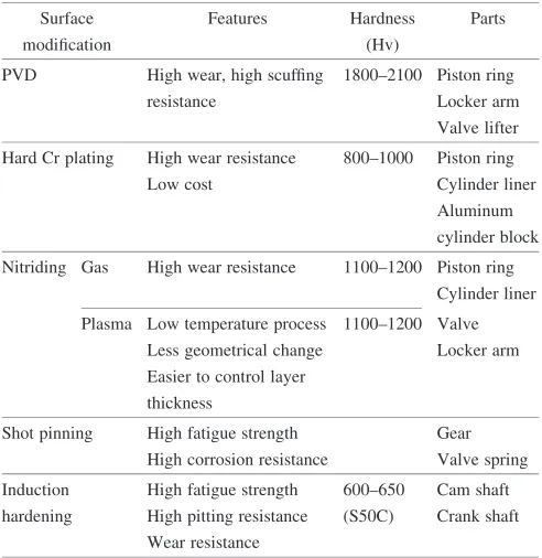
Severe usage of metallic alloy materials requires the surface treatment to further improve the wear resistance, the fatigue strength or the surface hardness. Typical examples can be seen in the automotive parts. Piston ring or cam/ follower must suffer from higher normal pressure and repetitive friction force even in dry condition.1) To refrain from severe wearing and frictional damage, various types of surface treatment methods have been developed. Table 1
listed typical surface treatment approaches for automotive parts.2)These methods are largely classified into two groups: surface modification and surface coating. In the former, the hardened zones, the affected zones or the precipitated layers are formed in the inside of the original matrix materials from its surface. Heat treatments or mechanical hardening are typical to these types of surface modification. Nitriding, carburizing or nitro-carburizing or carbo-nitriding3) have been used to improve the hardness profile. In these approaches, the nitride, carbide or their complex precipitates are formed inside the matrix from its surface. Depending on the type, the size and its distribution of these precipitates, the mechanical properties as well as the wearing/corrosion performance are positively controlled in practice. In the recent studies, the ion implantation enables us to change the old-fashioned concept of surface modification:4–6) chlorine implantation significantly reduces the wearing volume of sample and counter materials and the friction coefficient. This technological impact toward the dry forming and machining is to be further discussed in Ref. 7).
[image:1.595.46.292.531.784.2]The surface coating is another selection for improvement of surface material properties.8)Among various methods, the thermal/plasma spraying and the ion plating are typical approaches in industry. In the thermal spraying, the coating powders are once melt and deposited on the surface of materials, so that any protective layers can be formed on the specified surface portion of materials.9)While, the ion plating has been utilized to make hard ceramic coating on the tool or die surfaces in practice:e.g., titanium nitride coating by ion plating has become popular for cutting tools. In this surface coating approach, additional elements are necessary for coating to improve the original strength to matrix materials. Integrity of these coating layers is strongly dependent on the interfacial strength between coating and substrate materials. Table 1 Various types of surface treatment processings.
Surface Features Hardness Parts
modification (Hv)
PVD High wear, high scuffing 1800–2100 Piston ring
resistance Locker arm
Valve lifter Hard Cr plating High wear resistance 800–1000 Piston ring
Low cost Cylinder liner
Aluminum cylinder block Nitriding Gas High wear resistance 1100–1200 Piston ring
Cylinder liner Plasma Low temperature process 1100–1200 Valve
Less geometrical change Locker arm Easier to control layer
thickness
Shot pinning High fatigue strength Gear High corrosion resistance Valve spring Induction High fatigue strength 600–650 Cam shaft hardening High pitting resistance (S50C) Crank shaft
Wear resistance
Special Issue on Growth of Ecomaterials as a Key to Eco-Society
Sufficient joinability is required to preserve well-conditioned interface when undergoing severe shear stress and high flash temperature transients.
In the present paper, nitriding process is employed as a targeting process to discuss its technological impact toward the minimal emission in processing and the high-qualified surface treatment. Table 2 summarized various types of processes for surface treatment via nitriding. The common feature among these processes lies in the fact that resolved nitrogen atoms should penetrate and diffuse as an interstitial in the matrix material. How to generate the nitrogen atoms, or, how to preserve the nitriding mechanism, might be different in each method. At first, the fundamental concepts of three nitriding processes are surveyed to define their technological positions as an industrial surface treatment methodology: liquid-phase, gaseous phase and plasma nitriding processes. In particular, both the gaseous and plasma nitriding processes are compared with respect to environmental friendliness. As a case for application of nitriding, the piston ring is employed as a typical automotive part to demonstrate what is required for this type of surface treatment. Two types of steel samples are used to investigate the effect of sample alloys on the surface hardness and the scuffing load. The measured trade-off-balancing curves are utilized to discuss the technological impacts of plasma nitriding with comparison to other surface treatment meth-ods.
2. Environmentally Benign Nitriding Design
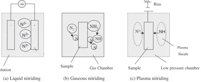
There are three industrial nitriding processes, each of which is working on the basis of its intrinsic principle as compared in Fig. 1. In the liquid-phase processing or the
liquid nitriding, nitrogen atoms are electro-chemically aligned on the surface for nitriding, or, nitrogen compound bases are assembled to the sample surface for nitriding. Hence, the inner nitriding takes place effectively; in particular, the liquid nitriding in the molten salt bath is widely used in industry as en efficient, productive surface treatment tool. Since most of liquid nitriding processes utilize the cyanides or cyanates as a solution, this type of nitriding must be denied as unfriendliness to environments. In the gas phase nitriding, the resolved nitrogen from ammonia is used for nitriding so that the external nitriding as well as internal nitriding take place together inevitably. Hence, the brittle externally nitrided layer formed on the surface, has becomes a nuisance of issue in production of automotive parts. Different from the above two methods, nitrogen-base radicals or ions are positively used in the plasma nitriding. Dependent on the processing conditions, no externally nitrided layers are formed and the thickness of inner nitrided layer is controlled by the duration time in nitriding. From the principles as a productive processing, each of three processes has merits and demerits; however, environmental consciousness plays more weight on the process selection. Even though the liquid nitriding has still merit as an industrial technology, use of molten salt bath must be against the ecomaterial selection.
Several processing features are compared between the gas and plasma nitriding processes. After discussion with Prof. T. Bell,10) the environmental friendliness of plasma nitriding can be summarized in Table 3 with comparison to gas nitriding. The most critical difference between two processes lies in the amount of NOxemission. In the gaseous nitriding,
since very small part of gaseous components is only used in nitriding, much NOxgas must be inevitably emitted from the
[image:2.595.47.548.84.177.2]process. In the case of nitro-carburizing, CO and CO2gases Table 2 Various types of nitriding processes to be available for surface treatment.
Item Processes Feature
Liquid Nitriding Salt-Bath Nitriding Chemical process in solution Electro-Chemical Nitriding
Gaseous Nitriding Ammonia Gas Nitriding Chemical process at ambient pressure
Plasma Nitriding (N2+H2)-Plasma Nitriding Chemical process at reduced
(NH3+H2)-Plasma Nitriding pressure
Solution
Sample
Sample Gas Chamber
Plasma Sheath
Low pressure chamber
(a) Liquid nitriding (b) Gaseous nitriding (c) Plasma nitriding
Sample
N2+ NH
Bias
N2 NH3
NH N
N N
− N3− +
N3−
N3−
[image:2.595.127.475.627.769.2]are also emitted from this system. On the contrary, very little emission of gases is usually experienced in the plasma nitriding. Hence, the plasma nitriding has the most environ-mental friendliness among three nitriding processes. In order that this plasma nitriding should be accepted as an envir-onmentally benign surface treatment in industry, its effec-tiveness as a practical surface treatment must be also verified. In the following, its application to surface treatment of steel automotive parts is employed to evaluate its high qualifica-tion as a manufacturing process.
Among various automotive parts, a piston ring is employed in the following experiments as a target for evaluation on the practical feasibility of plasma nitriding. In the global development of automotive part production firms, various types of surface treatments are developed to make life-time extension of parts. The brief survey was performed on the current status of the surface treatment techniques for piston ring. In the United States, thermal or plasma spray is a main stream for the whole types of piston rings. While, in Europe, the chromium plating is still a main technique in general. Although usage of chromium for surface treatment has been identified as a typical hazardous pollution, its cost-competi-tiveness is much weighed at present. In Japan, liquid nitriding is on the way to be abolished, but gas nitriding is still popular especially for large-scaled piston rings. Technological direction is shifted to CrN ion plating because of its high qualification. This survey implies that no feasible applica-tions are present for the plasma nitriding even if it has a potentiality of environmentally friendly processing. Hence, the plasma nitriding must be re-designed to have new technological impact, in order that it should be a candidate to replace the other processes or to compete with other surface treatment methods.
3. Plasma Nitriding of Steel Parts
[image:3.595.48.549.85.170.2]A systematic experiment was performed not only to investigate the effect of the plasma process conditions on the mechanical properties of the nitrided steels but also to describe the wear behavior of various nitrided samples by using the scuffing test. The details of our developing apparatus for plasma nitriding can be found elsewhere.11) Only its illustration was depicted in Fig. 2. DC-glow discharge was only utilized in the present system in order to simplify the nitriding source. Holding temperature was precisely controlled by the electric heater, with reference to the thermo-couple which was embedded into the sample holder.
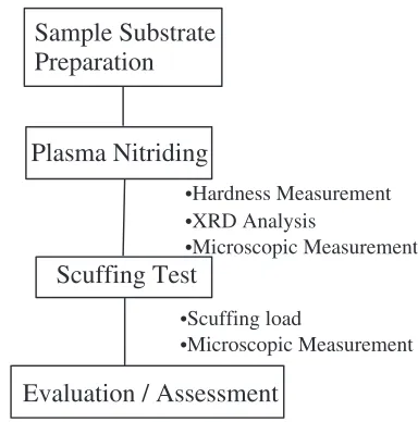
Figure 3 summarized the experimental procedure in the present study. As listed in Table 4, three types of steel
matrices were utilized: two commercial steels (SR34 and SR35) and one reference steel (Fe–Cr binary steel). Both two commercial steels are high-chromium alloys with 13 Cr and 18 Cr, respectively. In the preliminary experiments, SR35 indicated inferior data to SR34 with respect to the hardness and scuffing load of their nitrided specimens. Then, in the following experiments, only SR34 and Fe–Cr alloys were Table 3 Comparison of characteristic features between the gaseous and plasma nitriding processes.
Item Plasma Nitriding Gaseous Nitriding
Amount of gas used (m3h1) 0.6 6.0
Total carbon emission via CO/CO2(mg m3) 504 137, 253
Total amount of NOxgas (mg m3) 1.2 664
Output of residual carbon bearing gas (mg h1) 302 823, 318
Output of residual NOxgas (mg h1) 0.72 3, 984
1 3
4
5 7
8 9
10 13
2
11 12 6
(1) Specimen, (2) Dummy specimen, (3) Specimen table, (4) Heater (in quartz tube), (5) Cathode, (6) Insulator, (7) Thermocouple, (8) N2gas inlet, (9) H2gas inlet, (10) To rotary pump, (11) Ampere meter, (12) Voltage meter,
(13) DC power supply.
Fig. 2 Illustration of the plasma nitriding device.
Sample Substrate
Preparation
Plasma Nitriding
Scuffing Test
Evaluation / Assessment
•Hardness Measurement
•XRD Analysis
•Microscopic Measurement
•Scuffing load
•Microscopic Measurement
[image:3.595.324.534.198.379.2] [image:3.595.328.520.460.654.2]utilized for comparison of plasma nitriding with other surface treatments. The standard specimen size was7 mm8 mm 5 mm brick specimen for SR34 and SR35. With respect to Fe–14Cr alloys, a 10 mm10 mm10 mm cubic sample was nitrided and wrought to small pieces for testing. Table 5 summarized the plasma-nitriding conditions used in the following experiments. After nitriding, the hardness profile as well as the surface hardness, were measured by the Vickers hardness testing. Optical microscopic measurement was performed to identify the nitriding front end and the thickness of nitrided layer. With respect to the gas nitriding, the standard gas nitriding conditions were selected: TTD-967, -974 and -981.
The plasma nitrided Fe–14Cr is strengthened by fine precipitation of CrN in the bcc structured matrix or -iron matrix with low hardness. While, the plasma nitrided SR 34 is strengthened by fine precipitation of both CrN and0-Fe
4N
in the-iron matrix. In the latter, these0-Fe
4N precipitates were formed with the high volume fraction at the vicinity of surface, but no external nitriding layer was seen. This difference in precipitation reflects on the hardness and its profile in depth.
Among various methods to evaluate the wear toughness, the scuffing test was employed in this study. Figure 4 illustrated the scuffing load testing. In this testing, a sample test-piece was in contact with a bore material or a counter
material (boron-bearing cast iron or super-Tarcaloy) under the prescribed compressive load (W).Wwas controlled to be increasing with time, while the counter material was rotated with constant velocity. Only lubricant oil was pasted on the surface of the counter material at the beginning, but no oils were supplied in the subsequent process in order to simulate the intrinsic toughness of surface-treated layers in dry wearing conditions. W was increased from 20 N with the constant rate of 50 N/min. The rotating speed was also constant, 1 m/s. Under this increasing load, the frictional force or torque is nearly constant or slightly increasing due to abrasive wear on the contact surface. When a crack is generated or some softening occurs in the specimen, the friction load once reduces slightly but abruptly increases in the following moment because of total failure of a sample. This limit load is recorded as a scuffing load intrinsic to the surface treated sample material. Optical microscopic mea-surement was also made to describe the cracking behavior after scuffing test.
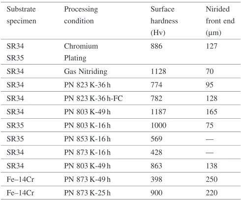
[image:4.595.49.558.84.141.2]Surface hardness (HS) and nitrided layer thickness (dN) of plasma-nitrided steel samples were listed in Table 6 together with the typical surface hardness and nitrided layer thickness for the chromium-plated and the gas-nitrided samples. In the standardized conditions of gas nitriding, the surface hardness only varies from 850 up to 1150 Hv and the nitrided layer thickness is limited to be less than 100mm. The chromium-plated sample has the thickness of 100–150mm with the average surface hardness near 900–1000 Hv. On the contrary, both the nitrided layer thickness and the surface hardness can Table 4 Chemical composition of prepared sample for plasma nitriding.
Specimen C Si Mn P S Cr Mo V
SR-35 0.6 0.4 0.4 0.03 0.001 13 0.3 —
SR-34 0.8 0.4 0.3 0.03 0.001 18 1.0 0.1
Fe–14Cr — — — — — 14 — —
[image:4.595.47.290.190.307.2]Chemical composition is measured by mass%.
Table 5 Typical plasma nitriding conditions in this experiment.
PH2 PN2 Voltage Current
(Torr) (Torr) (V) (A)
399 133 220 0.3
Temperature Holding time
(K) (h)
803 16, 49
823 9, 16, 25, 36, 49
853 9, 16
873 16, 49
W
Scuffing Load
Friction force
Time
Load
Fracture
x
SpecimenCounter material
Fig. 4 Illustration of scuffing loading test.
Table 6 Surface hardness and nitriding front end of the plasma-nitrided steel samples.
Substrate Processing Surface Nirided specimen condition hardness front end
(Hv) (mm)
SR34 Chromium 886 127
SR35 Plating
SR34 Gas Nitriding 1128 70
SR34 PN 823 K-36 h 774 95
SR34 PN 823 K-36 h-FC 782 128
SR34 PN 803 K-49 h 1187 165
SR35 PN 803 K-16 h 1000 75
SR35 PN 853 K-16 h 569 —
SR34 PN 873 K-16 h 428 —
SR34 PN 803 K-49 h 863 138
Fe–14Cr PN 873 K-49 h 398 250
Fe–14Cr PN 873 K-25 h 900 220
[image:4.595.304.549.569.772.2] [image:4.595.61.277.670.767.2]be varied in relatively wide range by using the plasma nitriding. For an example, 50<dN<250mm and
400<HS<1200Hv. This superior controllability in surface modification is the first merit of the plasma nitriding.
The hardness profile can be also controlled by the plasma nitriding. In the normally nitrided Fe–14Cr specimens, the hardness profile has a constant plateau to the nitriding front end. Across this end, the hardness abruptly decreases to the matrix hardness; this is a typical normal hardness profile measured for the plasma-nitrided samples. This hardness profile can be also controlled by the plasma nitriding conditions. Figure 5 compared the measured hardness distributions for two plasma-nitrided samples. The first specimen is a plasma-nitrided SR34 sample with the surface hardness of 900 Hv. At the vicinity of the nitrided layer, the hardness becomes nearly constant by 900 Hv but gradually decreases down to the matrix hardness (HM ¼350Hv) when approaching to the nitriding front end (d¼dN). The second specimen was a plasma-nitrided Fe–14Cr with the multi-stripe pattern. It has a lower surface hardness (HS¼400) but increases to 1000 Hv with the depth (d) ford<dN. Around
dN, the hardness abruptly decreases toHM (¼150Hv). This controllability of hardness profile must be the second merit of the plasma nitriding.
Through our recent works12–14) on the microstructure of the plasma nitrided specimens, formation of nitride precipi-tates can be also controlled by adequate selection of nitriding conditions. Figure 6 compared the normally plasma nitrided microstructure with the multi-striped pattern. In the normal microstructure, both iron and chromium nitrides were formed in the matrix as a precipitate together without formation of an externally nitrided layer. Then, as shown in Fig. 6(a), the
0 100 200 300 400 500
0 300 600 900 1200
(a)
Distance from Surface, d/µm
Vickers Hardness, H/ Hv
0 100 200 300 400 500
0 200 400 600 800 1000
1200 (b)
Distance from Surface, d/µm
Vickers Hardness, H/Hv
Fig. 5 Two typically measured hardness profiles for the plasma-nitrided steel samples: (a) Plasma nitrided SR34 at 803 K for 49 h and (b) Plasma nitrided Fe–14Cr at 873 K for 49 h.
[image:5.595.324.527.73.416.2] [image:5.595.67.527.470.757.2]nitrided layer can be identified as a single surface layer. This optical microstructure is just corresponding to the normal hardness profile. Since the surface hardness can be controlled by the precipitate volume fraction and its size in this normal plasma nitriding, the hardness profile has a constant plateau region from the surface to the nitriding front. On the other hand, a multi-striped pattern with the black-and-white sublayers was formed in Fig. 6(b). This pair of sublayers is composed of the CrN-precipitate rich phase for the black stripe and the dissolved Cr rich phase for the white one. These stripes were formed in parallel with the surface of sample irrespectively of the grain boundaries. Refs. 15) and 16) reported that multi-layer stacking of Cr-rich and CrN-rich sublayers, or, elasto-plastically deforming and highly strong sublayers, should be preferable to significant improvement of wear toughness. Hence, the nitrided samples with this multi-striped microstructure are expected to improve the scuffing load at the same level of surface hardness. This controll-ability of microstructure is the third merit of the plasma nitriding. Precise studies on this multi-striped microstructure formation, are necessary to quantitatively describe this formation mechanism.17)
4. Discussion
The relation of the scuffing load versus the surface hardness was employed to describe the effect of surface treatment on the mechanical performance in wearing. Figure 7 summarized the whole wear test data obtained by the present study together with the reference data. The whole data can be classified into three groups: Group I to III. Both the surface hardness (HS) and the scuffing load (SL) are categorized into one trade-off-balancing line in the case of the normal plasma nitriding and the gas nitriding for SR 34. These data are called here as a Group-II. As has been stressed
in literature,15,18)the scuffing load monotonically increases with the surface hardness. Then, this linear relationship becomes a ground design standard for the nitrided high-chromium alloy parts. From the measured data {HS,SL} for various plasma nitriding conditions, this ground design curve is expressed by
SL ¼0:12 ðHS430Þ þ610: ð1Þ
In the gas nitriding of SR34,HS¼1130Hv andSL ¼700N. The calculatedSLby eq. (1) becomes 694 N, so that the same scuffing load should be obtained even by the plasma nitriding. In other words, the gas nitriding can be replaced with the normal plasma nitriding by controlling the surface harness.
Group-I, including the reference data for the commercial CrN ion-plating and the chromium wet-plating,18,19) is located significantly above this ground design line. At the same level of surface hardness, the scuffing load can be improved by CrN coating or chromium wet-plating. Hence, the current industrial technological movement to CrN coating in Japan or chromium wet-plating in Europe, can be explained by this high qualification. On the contrary, Group-III is located in Fig. 7 below the standard line. These nitrided samples had the nearly the same surface hardness as those for Group I and II, but little endurance against wear is experienced in its use. This significantly low scuffing load might be attributed to the abrupt decrease from the high plateau of hardness to the matrix hardness. First in the following, let us further investigate the detail microstructure of samples in each group.
In this scuffing test, a single, small crack is generated, or, softening of stiffness takes place, at the certain scuffing load, where a small drop of the friction force is measured before its abrupt increase due to total failure of the specimen. Once a small crack or a deformation band is formed in the hardened materials, little or no loading capacity is left, resulting in the total failure of the whole material system. Figure 8 showed a
: Plasma nitrided Fe-14Cr alloy (multi-stripe microstructure) : Cr-plated Fe-0.8C-18Cr-Mo steel
: CrN coated Fe-0.8C-18Cr-Mo steel : Plasma nitrided Fe-0.8C-18Cr-Mo steel : Gas nitrided Fe-0.8C-18Cr-Mo steel
: Plasma nitrided Fe-14Cr alloy (Wagner-like microstructure)
Group I
Group II
Group III
0 200 400 600 800 1000 1200 1400 500
600 700 800
Surface Hardness, H/Hv
Scuffing Load, L/N
Fig. 7 Relationship between the surface hardness and the scuffing load for various plasma nitrided steel specimens together the chromium wet-plated and the ion-plated CrN coated samples.
[image:6.595.58.278.523.723.2] [image:6.595.325.541.537.756.2]typical optical microscopic observation of the post-test sample for group-I and -II. A single lateral crack was formed in the nitrided layer. The measured scuffing load is just corresponding to the critical shear stress to initiate the shear-type cracking. Essential difference of scuffing load between two groups originates from the fact that the critical strength for ion-plated CrN and wet-plated chromium should be higher than those by the normal plasma nitriding or the gas nitriding. On the contrary, many cracks and deformation bands were observed in Fig. 9. In this Group-III, the hardened layer is usually fractured to small fragments. No small drop of friction force was observed in the time history of the measured loads. Chipping behavior of the plasma-nitrided sample might be typically common to the group-III. Significant reduction of scuffing resistance is accompanied with fragmentation of the nitrided layer into many chips.
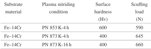
Plasma nitrided Fe–14Cr with the multi-stripe pattern provides higher scuffing load even at the relatively low surface hardness. Table 7 summarized the measured surface hardness and scuffing load data for three samples. In particular, in the case of the plasma nitriding at 873 K, the scuffing load can be increased with the duration time with the constant surface hardness ofHS¼400Hv. In this advanced plasma nitriding with multi-stripe formation, the number of stripes increases with the nitriding time. No change occurs in the surface hardness and the stripe width even with increasing the nitriding time. Hence, the above increase of scuffing load might be because the sufficient stack of alternative CrN-rich and Cr-rich sublayers is mechanically preferable to wear resistance.
In order to evaluate this high scuffing load at low surface
hardness, let us extrapolate this {400 Hv, 660 N} in the direction to increase the surface hardness by using the same gradient in eq. (1).SL ¼720N is calculated atHS¼885Hv, and,SL ¼760N, atHS¼1200Hv. These values are equal to or a little lower than those for Cr-wet plated and CrN ion-plated samples: {885 Hv, 720 N} for Cr-wet ion-plated sample and {1200 Hv, 780 N} for CrN ion-plated sample in Fig. 7. Hence, the chromium plating as well as the CrN ion-plating could be replaced by using this advanced plasma nitriding. The chromium plating is no longer useful as an industrial processing with consideration of environmental conscious-ness. For cost saving, use of CrN coating might be well used only in the designated applications. The advanced plasma-nitriding must be a most promising candidate to improve the wear resistance even in severe practical conditions.
The most attractive feature of the plasma nitriding for high qualification lies in the controllability of hardness distribu-tion and microstructure. In the advanced plasma nitriding, reactivity of solute elements in matrix with diffusing solute nitrogen can be directly controlled together with the nitride precipitation mechanism. In order to search for solutions against the commercial demand from automotive part market, higher controllability of plasma nitriding is indis-pensable. A new type of plasma nitriding device is to be developed to provide wide selection in plasma nitriding.
5. Conclusion
The plasma nitriding has grown up as a reliable methodol-ogy to be utilized for surface treatment instead of liquid and gaseous nitriding methods. The plasma nitriding has its original advantageous features as an environmental friendli-ness: little emission of gases or no pollution of gases and liquids. In the normal plasma nitriding, although the hardness profile as well as the nitrided layer thickness can be varied through the process, its mechanical performance is still limited by the standard trade-off-balancing curve between the surface hardness and the scuffing load. For the commercial high chromium alloy or Fe–0.8C–18Cr–Mo, the optimal scuffing load can be designed by controlling the surface hardness. The gas nitriding can be replaced by the normal plasma nitriding.
To be competitive with other advanced surface treatments for piston rings, the plasma nitriding has to improve the standard trade-off-balancing curve. Both the chromium wet plating and the CrN ion plating attained higher scuffing load than 700 N at the higher surface hardness over 900 Hv. The advanced plasma nitriding with the multi-stripe pattern can provide higher scuffing load of around 700 N even at the low surface hardness of 400 Hv. Hence, this advanced plasma nitriding can be utilized as a new approach to be working as a competitive or complementary method to the above two surface treatments. Although the success in the multi-stripe formation is still limited to high chromium binary alloys, this high qualification is promising to develop the plasma nitriding as an environmentally benign surface treatment. Fig. 9 Optical microscopic observation of the post-test samples in the
[image:7.595.55.283.71.231.2]Group-III.
Table 7 Effect of processing conditions on the surface hardness and scuffing load for the advanced plasma-nitrided samples with multi-stripe pattern.
Substrate Plasma nitriding Surface Scuffing
material condition hardness load
(Hv) (N)
Fe–14Cr PN 853 K-4 h 600 590
Fe–14Cr PN 873 K-4 h 400 645
[image:7.595.46.290.706.785.2]Acknowledgements
Authors would like to express their sincere gratitude to Dr. Novi Granito (Graduate School of Engineering, University of Tokyo) and Mr. Sameshima (NPR, Co.) for their help in experiments. This study is financially supported in part by the Grand-in-Aid from the Ministry of Education, Science and Technology, and by the Barrier-Free Project and the Inter-national Collaboration Project towards New Generation of Ecomaterials.
REFERENCES
1) A. Erdemir, M. Nordin, M. Larsson and S. Hognark: Soc. Auto. Engg. [1] (2000) 518–523.
2) H. Kuwahara, H. Matsuoka, J. Takada and I. Tamura: Plating and Coating10(1999) 54–59.
3) Gas carburizing. Metals Handbook 9th Edit. Vol. 4. ASM Publication (1981) 135–175.
4) A. Mitsuo and T. Aizawa: Mater. Trans., JIM40(1999) 1361–1366. 5) T. Aizawa, T. Akhadejdamrong, C. Iwamoto, Y. Ikuhara and A.
Mitsuo: J. Am. Ceram. Soc.85(2002) 21–24.
6) A. Mitsuo, T. Akhadejdaomrong and T. Aizawa: Proc. Powder
Metallurgy World Congress.1(2002) 23–36.
7) A. Mitsuo, T. Akahdejdamrong and T. Aizawa: Mater. Trans.44(2003) 1295–1302.
8) K. T. Rie and E. Broszeit: Surface and Coating Technology.76–77
(1995) 425–436.
9) R. W. Rigney and R. S. Brunhouse: Proc. Thermec 2000 (2000, Dec., Las Vegas) 226.
10) T. Bell: Abstract of Annual Meeting, ASM-International (2002, Oct., Columbus) 21.
11) N. Granito, H. Kuwahara and T. Aizawa: J. Mater. Sci.37(2002) 835– 844.
12) N. Granito, H. Kuwahara and T. Aizawa: Proc. 20th Heating Treating Conference, ASM-International, (2000, Oct., St. Louis) 227–232. 13) H. Kuwahara, T. Aizawa and N. Granito: Proc. 20th Heating Treating
Conference, ASM-International, (2000, Oct., St. Louis) 265–271. 14) N. Granito, H. Kuwahara and T. Aizawa: J. Jpn. Soc. Powder and
Powder Metallurgy48(2001) 494–500.
15) N. Granito, T. Aizawa and H. Kuwahara: Proc. 20th Heating Treating Conference, ASM-International, (2000, Oct., St. Louis) 347–352. 16) N. Granito: PhD Thesis, University of Tokyo, (2003).
17) N. Granito, H. Kuwahara and T. Aizawa: ISIJ-International (2003) (to be submitted).
18) Nippon Piston Ring: Private Communication (2001).