The Joint Characteristics of Friction Stir Welded AZ91D Magnesium Alloy
Won-Bae Lee
1;*1, Jong-Woong Kim
1;*1, Yun-Mo Yeon
2and Seung-Boo Jung
1;*21Department of Advanced Materials Engineering, Sungkyunkwan University,
300 Cheoncheon-dong, Jangan-gu, Suwon, Kyounggi-do 440-746, Korea
2
Suwon Science College, Hwasung, Kyounggi-do 445-742, Korea
This study was carried out to grow an understanding of the microstructural development of friction stir welding on an AZ91D magnesium alloy and to evaluate the mechanical properties of the welds. AZ91D plates with the thickness of 4 mm were used, and the microstructural development of the weld zone was investigated using optical and scanning electron microscopes. Square butt welded joint with good quality was obtained under 187 mm/min of travel speed with the tool rotation speeds range of 115 to 131 rads1. The microstructure near the welds
consisted of SZ (Stir Zone) which has fine equiaxed grains with no the original dendrite grain structure, TMAZ (Thermo-Mechanically Affected Zone), HAZ (Heat affected zone) and base metal. The microstructure of each zone showed very different features depending on the thermal and mechanical conditions. The hardness tests showed uniform distributed and slightly increased harness in the stir zone. Tensile strength of the stir zone was remarkably improved due to the fine recrystallized grain structure.
(Received October 21, 2002; Accepted March 26, 2003)
Keywords: friction stir welding, AZ91D magnesium alloy, welding parameters, recrystallization, grain refinement
1. Introduction
Magnesium alloys represent unique structural materials combining high specific strength with the capability to absorb
shock and vibration energy.1) For instance, cast Mg alloy
AZ91D containing 9 mass%Al and 1 mass%Zn has been most widely used in aircraft and engine building industries due to its high castability, low density, and good mechanical properties. However, the principal drawback of Mg alloy as a structural material is its high chemical activity leading in many cases to a low welding characteristics and corrosion resistance. This means that in the conventional fusion welding process there should be such a treatment procedure
before or after welding of Mg alloys. Munitzet al., according
to their paper about gas tungsten arc welded AZ91D magnesium alloy plate, reported that in spite of no defect in the weld zone, poor strength of the weld vicinity make it unsuitable for the use of as structural material. To overcome this problem, they proposed that one has to minimize the
HAZ by enforcing high cooling rate during solidification.2)
Mg alloys are currently welded by arc techniques, such as gas tungsten arc welding (GTAW or TIG) and gas metal arc welding (GMAW or MIG). Whilst reasonable welding speeds can be achieved, problems can be experienced with high welding residual stresses and changes in metallurgical structure due to the melting and resolidification. High purity shielding gases are necessary to prevent a weld contamina-tion. Mg alloys can also be laser or electron beam welded, but similar melt zone problems and porosity in the weld zone can
occur.3) These are the reasons why the conventional fusion
welding methods were rarely used in the welding of Mg alloys. It is, thus, very desirable that new joining technologies should be developed and made accessible for industrial usage. Friction Stir Welding (FSW) seems to be such a reasonable welding process at this point.
FSW was developed and patented in the early 1990s and
then has rapidly become an important industrial joining
process.4)
This new technique has resulted in low distortion and high joint strength compared to other techniques. Moreover FSW is capable of joining all kinds of Al alloys. But very little is
known about the weldability of Mg alloys5,6) since recent
studies have nearly restricted to that of Al alloys. There have to be more knowledge about the weldability of Mg alloys.
The objectives of this work are to develop an under-standing of the microstructural development of friction stir welds on an AZ91D Mg alloy, and to determine the optimum welding condition range without any defect in the welds and the mechanical properties of the welds.
2. Experimental Procedures
The material selected for this investigation was 4 mm thick as-cast AZ91D Mg alloy. The plates were cut to 140 mm long and 70 mm wide. The material was a commercial Mg alloy AZ91D with a nominal composition of 8.5 mass%Al,
0.75 mass%Zn, 0.3 mass%Mn, Cu and Ni below
0.001 mass%, and Mg as a balance. The complete chemical
composition is exhibited in Table1.
The range of the travel speed for the welds was between 32 and 187 mm/min, whereas the tool rotation speed varied from
115 to 377 rads1. Microstructural investigation and
analy-tical studies were carried out by opanaly-tical and scanning electron microscopy.
Prior to examination, the mechanically polished surface was chemically etched with the standard agent (4.2 g of picric acid, 70 mL of ethanol, 10 mL of glacier acetic acid and 10 mL of diluted water).
[image:1.595.305.550.753.782.2]Transverse and longitudinal tensile tests were carried out
Table 1 Chemical composition of AZ91D Mg alloy (in mass%).
Al Mn Ni Cu Zn Ca Si K Mg 9.1 0.17 0.001 0.001 0.64 <0:01 <0:01 <0:01 Bal.
*1Graduate Student, Sungkyunkwan University.
*2Corresponding author: sbjung@yurim.skku.ac.kr
to determine the strength of the welds. The schematic illustration of welding process and the transverse and the longitudinal tensile test specimens used in this test was as
shown in Fig. 1. Specially, the longitudinal tensile specimen
machined to 2 mm thickness to evaluate the strength of only the stir zone. The welding tool was rotated in the direction of clockwise and specimens, which were tightly fixed at the backing plate, were traveled.
3. Results and Discussion
3.1 Effect of welding conditions on Friction stir weld-abilities of AZ91D Mg alloy
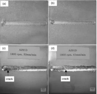
Figure2 shows the top surfaces of the welded specimens
with various welding conditions. AZ91D Mg alloy butt joints have good surfaces appearance after FSW for conditions of
115 to 131 rads1 of the tool rotation speed and 41 to
Fig. 1 Schematic illustration of weld and tensile test specimens: (A) transverse, (B) longitudinal.
Fig. 2 Surface appearances with various welding conditions (a) 131 rads1, 87 mm/min, (b) 131 rads1, 127 mm/min (c) 188 rads1,
[image:2.595.120.476.195.382.2] [image:2.595.128.470.427.757.2]187 mm/min of the welding speed. No exterior defect on the surface of all the joints is observed. However, the surface cracks are partially observed on the top surface for conditions
188 rads1, 32 mm/min and fully along the weld line for
conditions 188 rads1, 41 mm/min.
Figure3shows the cross-sectional macrostructures of near
the welds with various welding conditions. The welds show wider the upper surface than the lower surface because the upper surface experienced an extreme deformation and frictional heat caused by contacting weld specimens with a cylindrical tool shoulder. The shape of the weld zone is
mostly like wine cup. Satoet al.represented that the shape of
the weld zone may depend on the welded materials and their
thermal conductivity.7)
Very different microstructure is formed in the stir zone compared to that of base metal, which has an original dendrite structure. There are small defects, which were named as tunneling voids, in the retreating side of the stir
zone for the tool rotation speed range 168, 188 rads1at the
welding speed, 41 mm/min. This is mainly due to the brittleness of AZ91D and not caused by insufficient heat input. It is apparent that the stir zone exhibited a high degree
of continuity and no porosity for conditions of 131 rads1
regardless of the welding speed.
Figure4 shows the defect shapes in the stir zone with
different tool rotation speeds at fixed welding speed, 41 mm/ min. Fine recrystallized grain structure is formed and no
defect is observed in Fig.4(a). Small sized tunneling void, is
existed in the stir zone of 188 rads1. However, very large
defect named as lack of bonding is formed in the stir zone
over the rotation speed of 262 rads1.
Figure5 gives the brief summary of welding conditions
effect on the weldability of friction stir welded AZ91D Mg alloy joint using special marks. Both the surface crack and the lack of bonding in the stir zone are observed regardless of
welding speed over 188 rads1of the tool rotation speed. At
168 rads1of the tool rotation speed, the surface crack is not
detected by the optical observation and the tunneling void can be only observed in the stir zone. However, inner defect and surface crack are not observed for conditions of 115 and
131 rads1.
From the defect examination of the stir zone, the optimum welding condition range, which includes no defect in the weld zone, of FSWelded AZ91D Mg alloy are the rotation
speed range from 115 to 131 rads1 regardless of the
welding speed because there is no defect both surface and inner weld zone. However, the FSW conditions of cast AZ91D Mg alloy sheet without defect in the weld zone are
limited to narrow tool rotation speed as shown in Fig.5. This
is caused by its inherent poor formability of AZ91D Mg alloy
with lots of an intermetallic compound, Al12Mg17, existed in
the base metal.
3.2 Microstructure of the welds
Figure6 shows the SEM microstructures and the EDX
(Energy Dispersive X-ray) analysis of phase of the base
metal. The base metal is composed of a primaryphase and
Fig. 3 Cross-sectional macrostructures near the welds with various welding conditions (a) 188 rads1, 41 mm/min, (b) 168 rads1,
41 mm/min, (c) 131 rads1, 41 mm/min, (d) 131 rads1, 187 mm/min.
Fig. 4 Optical images of defect in the stir zone with various welding conditions (a) 131 rads1, 41 mm/min, (b) 188 rads1, 41 mm/min,
(c) 262 rads1, 41 mm/min, (d) 377 rads1, 187 mm/min.
0 50 100 150 200
0 50 100 150 200 250 300 350 400
x x
x x
x x
Tool Rotation Speed,
Rt
/ rad
. s
-1
Welding Speed, V/mm. min-1 crack Lack of bonding
Smooth Cavity
Smooth None
Surface Defect
Mark
×
[image:3.595.56.284.69.312.2] [image:3.595.312.541.70.241.2] [image:3.595.312.541.307.479.2]an eutectic structure which composed of Mg solid solution
and intermetallic compounds. However, AZ91 Mg alloy
can be roughly regarded as Mg–9 mass% Al binary because
other additives, Zn and Mn etc., are very little amount and
can be legible. From the equilibrium phase diagram of Al–
Mg,8) the sequence of solidification is Mg solid solution
followed by solid-state transformation ofMg solid solution
to intermetallic compound, Al12Mg17. However, actual
solidification brings the solute segregation during the
solidification process. Therefore, Mgsolid solution and
intermetallic compound were formed by an eutectic reaction during the non-equilibrium solidification.
Figure7 shows the microstructure near the welds. The
welds consist of 4 different regions which are unaffected base
metal (a), heat affected zone (b), thermo-mechanically affected zone (c) and stir zone (d). HAZ, which was received
more thermal effect, has smaller fraction of intermetallic
compound than that of the base metal due to resolution of
intermetallic compound. This result is well agreed to Mg–Al phase diagram. TMAZ, where both the thermal and the
plastic deformation effect were received, is composed of
intermetallic compound and partially observed recrystallized
grain structure. intermetallic compounds are arranged
along the direction of tool rotation. In the stir zone, the original cast structure of the base metal change to fine
recrystallized grain structure and intermetallic compound
disappears due to the resolution of phase intophase by
diffusion at elevated temperature.
Fig. 6 SEM micrographs of the AZ91D base metal (a) and EDX analysis of 3 point (b).
[image:4.595.126.470.71.302.2] [image:4.595.128.470.534.768.2]The temperature of the stir zone can be roughly estimated by the microstructure of the stir zone and Al–Mg binary
phase diagram (Fig. 8). When AZ91D Mg alloy was heated
at elevated temperature,intermetallic compound decreased
with temperature and this phase may be completely dissolved
over 370C. As shown in Fig.7(d), the microstructure of the
stir zone composed of only recrystallized Mg solid solution,
which means the temperature of the stir zone is over 370C.
The heating temperature do not exceed the solidus
tempera-ture, 500C, of the alloys because any cast microstructure
was not observed. These results mean that the temperature of
weld zone is estimated between 370C and 500C. This
estimation of the temperature of the stir zone is similar with
the experimental result ofT, Kagasawaet al., who reported
the temperature of the stir zone was heated up to 460C in the
case of FSWelded AZ31 Mg alloy.9)
Figures9and10show microstructures and the grain size
variation of the stir zone with various welding speeds at fixed
tool rotation speed 131 rads1. The microstructure of the stir
zone becomes irregularly and the grain size of the stir zone remarkably decreases with increasing welding speed. The
grain size of 41 mm/min welding speed is 19mm, that of
87 mm/min is 13mm and that of 187 mm/min is 7mm,
respectively. In FSW, the temperature of the stir zone should be increased as high as to raise the plastic metal flow to occur with ease. Heat input per unit length of the welds can be
expressed by simple equation Q=V, where Q is heat
generation by friction between the tool and materials andV
is travel speed. Q increases with increasing tool rotation
speed.10)Therefore, the heat input decreases with increasing
welding speed. The grain size of stir zone become larger with decreasing welding speed due to increasing heat input, which promoted the growth of the recrystallized grains.
Fig. 8 The binary Al–Mg phase diagram.
Fig. 9 Microstructures of the stir zone with various welding speeds at fixed tool rotation speed, 131 rads1 (a) 42 mm/min,
(b) 87 mm/min, (c) 127 mm/min, (d) 187 mm/min.
20 40 60 80 100 120 140 160 180 200
0 5 10 15 20 25
Grain Size of Stir Zone
,
D
/µ
m
[image:5.595.332.520.315.468.2]Travel Speed,T/mm. min-1
[image:5.595.130.470.520.758.2]3.3 Mechanical properties
Figure11 shows macrostructure and horizontal hardness
profiles of the transverse cross section of the weld joint for
conditions 131 rads1, 41 mm/min. The base metal has a
very wide range of hardness, which is measured
approxi-mately from 50 to 70 Hv. The base metal is composed of
solid solution and intermetallic compound. The Mg solid
solution, which is softer thanintermetallic compound, has a
large volume fraction. If the measured hardness indenter
were located near primary phase than eutectic phase, the
hardness is about 50 Hv. However, in the opposite case, the hardness of the base metal shows over 70 Hv.
Therefore, the hardness of the base metal is very different as measured locations. The hardness of the stir zone is slightly increased and showing relatively uniform distribu-tion. These kinds of tendencies are most likely to be due to
the recrystallized and fine grain structure.11)
Figure12shows the horizontal hardness profiles near the
welds with various welding speed. As the welding speed increases, the average hardness of the stir zone remarkably increases. These results are mainly caused by the grain refinement. However, at higher welding speed, the hardness of the stir zone is non-uniformly distributed by
microstruc-tural irregularity.
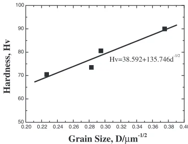
The effects of the average grain size on hardness in the friction stir weld can be estimated using the hardness data
(Hv) and the grain size (D) of the weld. The Hall-Petch
relationship relatesHvtoDthrough the following equation
Hv¼H0þKhD1=2
Where, H0 and Kh are appropriately constant. Figure13
plotsHvagainst the reciprocal of the square rootDfor the stir
zones of AZ91D Mg alloys. The extrapolated values for a boundary-free condition and slope of the Hall-Petch equation
with various weld conditions give value ofH0¼38:6Hv and
Kh¼135:74Hvmm1=2, respectively.
Figure14 shows the transverse and longitudinal tensile
strength with various welding conditions. The base metal has 110 MPa ultimate tensile strength from these experimental results.
The transverse tensile strength shows constant and almost the same values in comparison to that of the base metal regardless of welding speed. Since the transverse tensile specimens is composed of the stir zone and unaffected base
metal. The non-uniformed distributedintermetalllic phases
[image:6.595.49.288.375.555.2]and shrinkage defects existed in unaffected base metal act as a preferential crack initiation. Therefore, all of the tensile specimens are fractured at unaffected base metal and shows the similar ultimate tensile strength with that of the base metal.
Fig. 11 Macrostructure (a) and horizontal hardness profiles (b) of the transverse cross section of the weld joint at condition of 131 rads1with
41 mm/min.
-15 -10 -5 0 5 10 15
30 40 50 60 70 80 90 100 110 Hardness, Hv
Distance from Weld Center, L/mm
[image:6.595.329.521.418.565.2]41mm/min 87mm/min 127mm/min 187mm/min
Fig. 12 Hardness distributions of the welds with various welding speeds.
0.20 0.22 0.24 0.26 0.28 0.30 0.32 0.34 0.36 0.38 0.40
50 60 70 80 90 100 Hardness, Hv
Grain Size, D/µm-1/2
Hv=38.592+135.746d-1/2
Fig. 13 Effect of the grain size on the hardness in friction stir welds of AZ91D Mg alloy.
20 40 60 80 100 120 140 160 180 200
0 20 40 60 80 100 120 140 160 180 Tensile Strength, σu /MPa
Welding Speed, v/mm. min-1
Longitudinal Transverse
[image:6.595.73.265.622.767.2]Tensile strength of the base metal
[image:6.595.332.522.623.769.2]However, the longitudinal tensile strength shows higher values than that of the base metal. The longitudinal tensile specimens only include the stir zone which has a recrystal-lized fine grain. Homogenous microstructure results in uniform deformation during the tensile test. This is a reason why the longitudinal tensile specimen has the higher tensile strength. The longitudinal tensile strength is slightly in-creases with increasing welding speed because the grain size becomes smaller as increasing welding speed. Small increase of longitudinal tensile strength compared to hardness increase with decrease grain size can be explained by the
equation ofHv¼3y12)which roughly expressed the relation
between hardness and strength. And the irregularity of the recrystallized grain structure also affected the tensile strength at higher welding speed.
The longitudinal tensile strength has a range of 142 MPa and 162 MPa, which is almost 145% of joint efficient, in comparison with that of the base metal.
4. Conclusion
In this study, the microstructural development and me-chanical properties of the friction stir welded AZ91D 4 mm thick plates have been determined. The results obtained are summarized as follows.
(1) AZ91D Mg alloy was successfully joined using friction stir welding under the optimum conditions ranges of 41 to 187 mm/min of welding speed with 115 to
131 rads1 of the tool rotation speed.
(2) It has been confirmed that the original base metal grain structure became completely eliminated and replaced
by very fine and equiaxed grains in the stir zone.
-intermetallic phase which was in the base metal was dissolved by the frictional heat input.
(3) Temperature of the weld zone could be roughly
estimated to the range of 370C to 500C by
micro-structure observations and Mg–Al phase diagram. (4) The mechanical properties, such as hardness and tensile
properties were improved due to the refinement of the grain structure in the stir zone.
REFERENCES
1) S. Lee, S. H. Lee and D. H. Kim: Metal. Mater. Trans. A29(1998) 1221–1235.
2) A. Munitz, C. Cotler, A. Stern and G. Kohn: Mater. Sci. Eng. A302
(2001) 68–73.
3) S. A. Lockyer and M. J. Russell: Proc. of Third International Symposium on Friction Stir Welding, ed. by P. Treadgill, (The Welding Institute, 2001).
4) C. J. Dawes: Weld. Met. Fabrication63(1995) 13–16.
5) K. Nakata, S. Inoki, Y. Nagano, T. Hashimoto, S. Jorgan and M. Ushio: J. of Jpn. Inst. of Light Met.51(2001) 528–533.
6) W. B. Lee, Y. M. Yeon, Shae. K. Kim, Y. J. Kim and S. B. Jung:
Magnesium Technology 2002, ed. by H. I. Kaplan, (TMS (The Mineral, Metal and Materials Society), 2002) pp. 309–312.
7) Y. S. Sato, H. Kokawa, M. Enomoto and S. Jorgan: Metall. Mater. Trans. A30A(1999) 2429–2437.
8) T. B. Massalsk:Binary Alloy Phase Diagrams, Vol. 1, (ASM, Ohio, USA, 1986) pp. 169–171.
9) T. Nagasawa, M. Otsuka, T. Yokota and T. Ueki: Magnesium Technology 2000, ed. by H. I. Kaplan, J. Hym and B. Clow, (TMS (The Mineral, Metal and Materials Society), 2000) pp. 383–386. 10) O. Frigaard, O. Grong and O. T. Midling:Preprint of INALCO’98, ed.
by M. H. Ogle (The Welding Institute, 1998) pp. 197–207.
11) K. Nakata, S. Inoki, Y. Nagano, T. Hashimoto, S. Jorgan and M. Ushio:
Proc. of Third International Symposium on Friction Stir Welding, ed. by P. Treadgill, (The Welding Institute, 2001).