Pilot Placement for Time-Varying MIMO OFDM Channels
with Virtual Subcarriers
Alieh Moradi, Hamidreza Bakhshi, Vahid Najafpoor Electrical Engineering Department, Shahed University, Tehran, Iran
E-mail: moradi@shahed.ac.ir
Received October 13, 2010; revised January 7, 2011; accepted January 19, 2011
Abstract
The rapid time-variation of a fading multipath environment can impair the performance of multiple-input multiple-output orthogonal frequency division multiplexing (MIMO OFDM). This paper proposes a pilot placement method for MIMO OFDM systems under time-varying channels with the guard band. The time-varying channel is described by complex exponential basis expansion model (BEM). We discuss the least square (LS) channel estimation to obtain the minimum mean square error (MSE) and derive the pilot allocation that can satisfy the minimum MSE with regard to guard band in time-varying channels. It is shown that optimal pilot clusters can distribute non-uniformly in frequency domain and minimize the MSE. We generalize our scheme over G OFDM symbols and compare it with comb pilots. It is demonstrated that the
proposed approach is more effective than previous work. Simulation results validate our theoretical analysis.
Keywords:Guard Band, MIMO OFDM, Pilot, Time-Varying Channel, Virtual Subcarriers
1. Introduction
Orthogonal frequency division multiplexing (OFDM) gives an effective technique for high data rate transmis-sion. A multiple-input multiple-output (MIMO) system increases system capacity and provides diversity in fad-ing environment [1]. The combination of MIMO and OFDM offers high system throughput.
A pilot signal design is presented in [2] for MIMO OFDM system. The least square (LS) channel estimation is used for channel coefficients. To obtain the minimum MSE, an equal-powered, equal-spaced and phase shift orthogonal pilot sequence is suggested. In [3], the train-ing sequences are designed for OFDM system where pilot tones satisfy the optimal conditions. The placement of pilot symbols is studied in [4] for single-carrier and OFDM systems. The problem of setting and design of pilot sequences is considered in [5] for the frequency- selective channel estimation. The Cramer-Rao Bound (CRB) in order to the minimum MSE of the channel es-timation is computed for both single-input single-output and MIMO systems. The optimal pilot allocation is de-scribed in [6] for OFDM system. As supposed in it, the channel must be quasi static and have a finite impulse response. The energy exchange between the pilot and data is also derived optimally. In order to derive an
op-timum estimation, [7] also discussed the selection of pi-lot tones. As shown in it, the training sequences with equal space have the best performance. In [8], the train-ing sequences with virtual subcarriers are presented. The pilot placement is non-uniform and gives the minimum MSE of the LS channel estimation. In practice systems, the presence of the virtual subcarriers can cause non- uniform pilot placement. To achieve optimal conditions, it applies the algorithm which is given in [9] for solving the linear inequalities. In [10], a pilot design scheme for the LS channel estimation is described in MIMO OFDM systems. A suboptimal pilot sequences is also suggested for reduction of the training overhead. General groups of pilot sequences are addressed in [11] for frequency-se- lective channel estimation in MIMO OFDM systems. Various pilot sequence allocations are arranged for each transmit antenna. These allocations are organized as fol-lows: time-division multiplexing, frequency-division multiplexing, code-division multiplexing in the frequency domain and in the time domain, and different combina-tions of them.
matrices for fading channels is considered. The pilot signals are used for obtaining the channel coefficients. The channel variations are modeled as multichannel autoregressive (AR). The peaks of the AR spectrum show the Doppler frequencies.
A pilot approach is considered in [14] for MIMO OFDM systems in time-varying channels. To increase the performance, the inter-carrier interference (ICI) due to time variations must be decreased in high delay envi-ronments. In [15], the channel estimation for MIMO OFDM systems is expressed in linearly time-varying channel. The channel coefficients of the linearly time- varying channel are based on complex exponential basis expansions model. In direct sequence code division mul-tiple access (DS-CDMA) systems, [16] expresses an adaptive estimation of Doppler shifts for several Doppler sub-paths. The channel model is based on basis expan-sion model (BEM). For suppresexpan-sion of ICI in time- varying channel, [17] presents an analytical framework dependent on the known statistical properties with mo-bile radio channels. [18] uses a parallel removal tech-nique for discarding ICI in frequency domain. It is sup-posed that the channel impulse response (CIR) changes linearly along a block period. For time-varying frequency- selective channels, a general framework is described in [19] to achieve the optimal pilot overhead and the opti-mal pilot boost. For single-input multiple-output time- varying channels, blind channel estimation is given in [20], where the time-varying channel is expressed as a complex exponential basis expansion model (CEBEM). For frequency-selective fading channel estimation, a rectangular-windowed least square estimation is studied in [21], relying on a polynomial model of the time- varying channel delays. For channel estimation, a new block differential codec is derived in [22]. The time- varying channels are described as a basis expansion model. By using the BEM, block differential design has a simple implementation, and derives the maximum Dop-pler diversity in the time-varying channels.
So as to discard the interference between neighboring channels in practical systems, a guard band is considered at each transmit data symbol. The guard band includes virtual subcarriers that are not used for transmission. In [23], a pilot placement is suggested regard to the guard band. It implies that comb pilots with the largest distance between pilot tones have the best effectiveness by ex-ploiting the equivalence of the Toeplitz and circulant matrices. In this paper, we suggest an optimal pilot allo-cation that does not rest in the guard band based on the minimum MSE under time-varying channel. We also show that our new scheme has better performance than comb pilots.
The remainder of the paper is organized as follows:
Section 2 expresses the basis expansion model for time- varying channels and describes the MSE of the LS channel estimation. To obtain the minimum MSE, the optimal conditions are also derived in this section. In Section 3, we introduce a new pilot allocation that is op-timal with respect to virtual subcarriers. We organize our method over G OFDM symbols in Section 4. Section 5
contrasts our scheme with comb pilots. Section 6 pre-sents the simulation environment and outcomes, and shows improvement in our design. Eventually, the con-clusions are expressed in Section 7.
Notations: tr .
is used to show the matrix trace.
., and
.T
.Hexpress conjugate, transpose and conju-gate transpose respectively. is applied for the cyclic convolution. Expectation is presented by
.E . The
ceiling of a number is shown by . denotes the set of integer numbers. Bold letters is presented for matrices (column vectors) and variables are displayed in italic.
.
2. System Model
The desired system is depicted in Figure 1. It is a MIMO OFDM system with t transmit antennas, r receive
antennas and K subcarriers. The length of channel
im-pulse response (CIR) is equal to L for each
trans-mit-receive antenna pair. A cyclic prefix (CP) with length V is inserted to form a complete OFDM symbol.
The CP is considered to be larger than the largest multi-path delay. The channel estimation procedure is applied similarly at each receive antenna, so we assume to have
transmit antenna and one receive antenna.
N N
t
N
Let S ni
be the data symbol on nth time sample atith transmit antenna. After removal the CP at the receiver,
the output can be written as
1 ,
1 0
t
N L
i l i i l
Y n h n S n l N n
(1)where n0,1, , K1 and is additive
Gaus-sian noise with zero mean and variance of
N n
2
n
. The channel coefficient can be approximated by a complex exponential model as
2 2, , ,
2
qn
Q j
N i l i l q
q Q
h n h e
(2)where i l q, , is zero mean, complex Gaussian random
variables with equal variance . Since the BEM is periodic with period of N and the real channel is not
periodic, N must be larger than the length of transmit
data, i.e., . h
2 , q l
xT Ks
NK Q 2fma , fmax is the maxi-
mum Doppler frequency, Ts T1 is the sample
in-terval and is the total interval of data symbol [14].
K
1 T
Figure 1. System model.
, 2 , 0 1, 0 1j kn K
K K k n e k K n K
F (3)
1 , , 2 20
,
ql kl
L j j
N K
i i l q
l
H k q h e e
(4)
0 2 1, , 2 , , 2 1T
q K q qn
j j j
N N N
q e e e
V F (5)
then, with above definition, the fast Fourier transform (FFT) of Y(n) is given by
2
1 2
, t
N Q
i q i
i q Q
Y k H k q k N k
V X (6)where k0,1, , K1 and N k
is the FFT ofwith variance of
N n 2. i is the transmit data
vector in frequency domain, i.e., . X
i i
X F S Vq
kdenotes a cyclic shift vector of with a shifting length k.
0q
V
As discussed in [15], the major power of the vector concentrates on two ends. So,
0q
V Vq
0 can beapproximated by
20
0 , , ,0, ,0, , , 1
q
T
q q q q
qn j
N q
V V T V K T V K
V n e
V
(7) where T is a positive number. T = 2 or 3 is sufficient for
involving the principal lobe of Vq
0 . Since thecon-volution between Vq
0 and is only performed at2T + 1 sequential tones around the tone k, we use pilot
clusters with length 2T + 1. We consider pilot clusters on
a set of subcarriers
i X
k k1, , ,2 kP
. P denotes the
number of pilot clusters. So the pilot sequences at the pilot cluster kp is
T
, ,Xi
kp T
i kp Xi kp X at ith transmit an-
tenna. Define:
Vq
k Xi
kp ,i q p
w k (8) 2
, , , ,
ql j
N i l q i l q
H h e
(9)
2 p, , ,
k l j
N q p i q p
R k w k e
i l (10)
Then at all pilot clusters, the Equation (6) can be writ-ten as
Y RH Ν (11) where R is a P N L Q t
1
matrix. The least squarechannel estimation, supposingR RH has full rank and
1
t
PN L Q , is given by [24]
1ˆ H H
H R R R Y (12) From (12), the MSE of the LS channel estimation can be obtained as
2
2
2
1 ˆ
1 tr 1
t
H
t
E
Q LN
Q LN
H H
R R
MSE
In order to obtain the minimum MSE of the LS chan-nel estimation with fixed energy allocated for pilot sequences, we must have i
E
1
t
H
i LN Q
E
R R I (14) where I shows an identical matrix. For achieving (14) and minimizing the MSE in (13), we must satisfy the following condition as
2
, , 0
1, , 1 0
km j
K i q i q
k
r m w k w k e
m L L and m
E (15)where r
0 i. For qq, we have
2
, , 0
1, , 1 and , { 2, , 2
km j
K i q i q
k
s m w k w k e
m L L q q Q Q
(16)finally, for two different transmit antennas and qq,
we require
2
, , 0
1, , 1 and
km j
K i q j q
k
d m w k w k e
m L L i j
(17)3. Pilot Placement with Guard Band
In practical system, some of subcarriers are not use for transmission that called virtual subcarriers. The virtual subcarriers set in the guard band. For avoiding the inter-ference between communication channels, the guard band is considered at each transmit data sequence. The transmit subcarriers are assumed to be belonged to
0, 1, ,
2 2 G K K
where KG denotes the number of the virtual subcarriers.
The purpose is to estimate the channel impulse response under time-varying channel with guard band. Therefore, we suggest the pilot placement that minimizes the MSE in the presence of the guard band under the BEM.
As discussed in previous section, for minimizing the MSE, the conditions (15), (16) and (17) must equal to zero. In this paper, for simplification, it is assumed K is
even and KG is odd. Let E K K. Define M as the
number of pilot cluster groups at each transmit symbol, where E is the number of pilot clusters and is the
distance between pilot clusters at each groups. So, we have M pilot cluster groups at each transmit antenna.
Since pilot tones are outside the guard band, the distance between pilot clusters at each group must be larger than the length of the guard band, i.e., G
K
K K
. The condi-tion of full rank shows that we should have at
least
H
R R
1
t
N L Q pilot clusters, i.e. EN L Qt
1
. Con-sider
a
(h) is the power allocated for each pilot in hthgroup, where h i h
a E E. The following pilot allo-
cation is proposed as
2 , 1 ; 0, h p i q pa k
w k
, 2
elsewhere;
e K h T
(18)
where
K 2
KG1
2
T , 0,1, , and1
e E
0,1, , 1
h M . The problem is to find M and
imply that the pilot allocation (18) satisfies (15), (16) and (17) with regard to the guard band.
1) for e = 0 and h = 0, the relation (18) can be
ex-pressed as
2 0, first , first
i q p p
w k a k 1
2 2 G K K T
(19)
as seen, kp is the middle tone at each pilot cluster. So,
the first tone places at kpT and the last ton sets at
p
k T . kpfirst T
K 2
KG1
2
is the firstedge of the subcarriers that is outside the guard band. 2) for e = E − 1 and h = M − 1, we have
2 1 , last last ,1 1 2
M i q p
p
w k a
k E K M T
1 (20)
where kplastT is the last tone of the last cluster that
should be outside the guard band. It means
last 1 2 2 G p K K
k T (21)
E 1
K
M 1 2
T 1
T T (22)
then, M can be written as
2 1 G K K M T
(23)
for above M, our proposed pilot placement do not
in-clude the virtual subcarriers. Figure 2 illustrates subcar-riers with guard band.
Now, we should demonstrate this pilot allocation zeros (15), (16) and (17).
3) with substituting condition (18) in (15), it can be given by
2 2 1
,
0 2 2
1 2 2 1 2
2 1 2 1
1 2
j e K h T m K h
e h
j m K j m e K K e
j T m K j m e K K e
j M T m K
M j m e K K e
r m a e
a e e
a e e
a e e
Guard band Guard band
Figure 2. Subcarriers with guard band.
it is implied
1
2 2 / 2
0 1 2 1 1 0 E 1
j m e K K j m K K j m K E K e
E j j j
E E E
e e e
e e e
(25)where 2m. We corroborate that r(m) is ze
cation. For minimizing the MSE,
ro for
ur pilot allo s(m) and
lso become zero.
ifferent transmit antennas and o
d(m) should a
4) for two d qq, the
training sequence is designed as
2 1 2,
j i q Q Le E h
i q p
w k a e (26)
After, setting (26) in (17), it can be obtained
1
0
0 1, , 1 &
E
j j
h K E
h e
d m a e e
m L L i
(27)2 2 1 2
or
h T m e
j q q
where
i j q q L
m. Since ENtL Q
1
, is always smaller than E and 1
2
0
E
j e E e
e
becomesze ew pilot
pl ard to the
guard band that minimizes the MSE and achieves the optimal conditions. We can generalize our sch
G OFDM symbols.
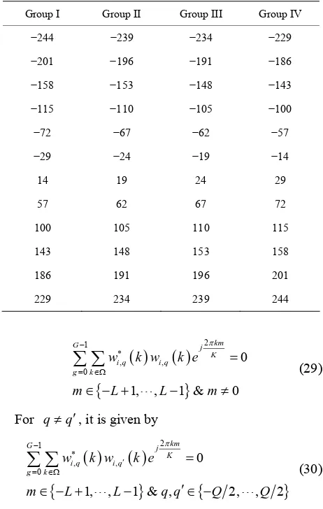
Table 1 shows an example of our pilot allocation in oups. Consider two tra tennas. Let K
516, L = 3, Q = 1 and T = 2. As known
ro for all m. Therefore, we introduce a n
acement under time-varying channel with reg
eme over
four gr nsmit an =
23
KG ,
1
t
N L Q
, so we choose E = 12 K 43
E and .
Relation (23) provides M = 4. Each group has 12 pilot
clusters and each cluster requires 5 pilot tones.
4. Pilot Placement over
G
OFDM Symbols
In this section, we suppose G OFDM symbols at each
transmit antenna. Let .
g i qw k be wi q,
k at gthOFDM symbol. is consideration, condition (14)
1 1 t G
gH g
i LN Q
E
R R I With thchanges to
(28)
0 g
where R g is R at
gth OFDM symbol.
Fro , conditions (15), (16) and (17) can be as
m (28) ten
Table 1. Placement of pilot clusters for Nt2, 516K , 23
G
K , 3L and E12.
Group I Group II Group III Group IV
−244 −239 −234 −229
−201 −196 −191
−143
−57
−2 −19 −14
−186
−158 −153 −148
−115 −110 −105 −100
−72 −67 −62
9 −24
14 19 24 29 57 62 67 72 100 105 110 115 143 148 153 158 186 191 196 201 229 234 239 244
2 1 , , 0 0 1, , 1 & 0km G j K e i q i q g k
w k w k
m L L
(29) For m qq, it is given by
2 1 , ,1, , 1 & , 2, , 2
km
G j
K i q
g k
w k w k e
m L L q q Q Q
)For two different transmit antennas and
0
0
i q
(30
qq, it can
be obtained as
2 1
, ,
0k i q j
0 1, , 1 &
km
G j
K q
g
w k w k e
m L L i j
(31)To achieve (29), we can write (18) as
1 2
,
0 0, elsewhere;
g
1
M h
, 2 1 ;
h G
p i q p
a k e K h T
w k
(32)where 0 0 h a
.From (30) and (31), we can express
1 ; (33)
1 , , , 2 0, elsewhere; Gi q p j q p
h p w k w k
a k e K h T
[image:5.595.307.540.110.467.2]5. Comparing the Proposed Method with
Comb Pilot
scribed pil quences that can minimize the r time-varying channel with virtual subcarriers.
N od with comb
pi-lots which have equal space and equal power without crossing the guard band. In [23], comb pilots are used for single input single output OFDM systems in the
of the guard band. Without considering the vi
carriers, pilots with equal space and equal power can optimize (13) with uniform eigenvalues. As known, comb
ti-3] r timal scheme. The equivalence of r(m),
We de ot se
MSE fo
ow, we interest to contrast our meth
presence rtual
sub-pilots do not place in the guard band and can not op mize the MSE of the LS channel estimation. So, [2
esents a semi-op p
with assumption of [23], is given by
2
0
1, 2, , 2, 1
kn K j
K k
r n R k e
n L L L L
(34)
for k , R(k) is equal to 1, i.e., R k
1. Let Pbe the number of pilot clusters which distribute symmet-ric about the origin. Then, we have
2
3
, , ,
2 2 2
P
d d
d d
. The inverse dis-
crete Fourier transform of R(k) is written as
sind n
sin
P K r n
d n K
(35)
nergy with rai r
has the narrowest main lobe.
If we choose r(m) of con
the e of r(n) diminishes rapidly sing n fo
comb pilots. It is shown in [23] that comb pilots with larger distance between pilot tones have better signal to noise ratio because the largest space
1
i
E , dition (15) will be
equal to one for m=0, i.e., r
0 Ei andzero for m0. Thus, r(m) illustrates an im
will become pulse func-tion. Wi eration ivalence to r(n)
given in sed
(15), (16) mp
has the obe es zero suddenly
trans
modulatio ed to have
DM
th this co [23]. Ou and (1 narrowest
nsid r propo 7). In co main l
, r(m) is equ
meth arison
and becom
od achieves conditions with comb pilots, r(m)
in m 0. Therefore, our proposed pilot setting is
opti-mum while comb pilots are sub-optimal.
6. Simulation and Results
W
e consider two mit and two receive antennas for MIMO OFDM system. The n mode is chosen as BPSK. The channel is suppos L = 3 and V =
5. The OF symbol size is selected as K=516 and the
length of the guard band is KG 23. We assume that
the channel coefficients are distributed identically and independently by complex Gaussian random process. The symbol rate is fs 1 MHzor Ts 1 μs and the
ma Doppler frequency is fmax 100 Hz. N =
5120 is chosen, where N > K. We select Q
ximum
T = 2,
the length of the p nown,
der E
= 1 an 1 = 5. A
1
. C d s k onsi so ilot cluster is 2T +t
N L Q E must be equal or larger than
12 and K 43
= because of E K K. The relation
(23) shows that M can be at most 4. We only suppose
two groups in our simulation in Figure 3 and Figure 4,
i.e.,M = 2. The number of total pilot clusters is ME = 24
and the total pilot tones are equal to (2T + 1) ME = 120.
The multi-path density profile is considered as
exp 0.1 /
c Ts
and the Doppler power spec- trum is
2 2
1max c
S f f f
[image:6.595.57.288.312.468.2] , where fmax f .
Figure 3 shows the bit error rate signal to noise ratio (SNR) for the time-varying BEM. The dis-tance between comb pilot cluster 1 is d = 20 and the pilot
clusters are belonged to the set 0, , 230 . The set of ot cluster 2 is
(BER) versus
comb pil
10, 3
9, 27, , 207
, where the distance between them is chosen as d = 18. The amplitude of pilot tones is
equal to each other. The pilot clusters of proposed ap-proach are placed at
244, 201, , 229
, whereup IV in these tones are selected from group I and gro
Table I. The amplitude o tion (26). Since we only zero. As seen, t ter
f pilot tones is followed by have two groups, so a 1 and
2
a are he comb pilot cluster 1 has
effectiveness than comb pilot cluster 2 because of the larger distance between them. The proposed approach yields performance improvements greatly compared to comb pilot clusters.
Figure 4 illustrates the MSE v
pilot cluster 1, comb pilot cluster 2 and proposed ap-proach. By comparison between curves, it is concluded that the proposed scheme is the best.
Figure 5 compares the MSE of proposed approach for different Doppler frequencies as fmax 100 Hz, 200 Hz
and 500 Hz. We consider four groups and the total pilot tones are 240, therefore a 1 and a 2 are non-zero.
T simulation results show that the effectiveness of the MSE is decreased with increasing Doppler frequency.
7. Conclusion
ersus SNR for comb
he
In
annels and then, we expressed the optimal conditions based on the mini-
Figure 3. BER performance for pilot placement, K516, 23
G
[image:7.595.62.286.303.471.2]K , E12 and L3.
Figure 4. MSE performance for pilot placement, K516, 23
G
K , E12 and L3.
Figure 5. MSE performance for different Doppler
fre-quency, and
mum MSE. We suggested a new pilot allocation that is distributed non-uniformly with non-equally powered pilot tones. We arranged the proposed pilot cluster over G
OFDM symbols and gave an example of the pilot setting in four pilot groups. After contrasting our design with comb pilots, it was shown that the proposed scheme im-proves SNR. Simulation results also verify our idea.
8. References
[1] M. Jankiraman, “Space-Time Codes and MIMO Sys-tems,” Artech House, London, 2004.
[2] I. Barhumi, G. Leus and M. Moonen, “Optimal Training Design for MIMO OFDM Systems in Mobile Wireless Channels,” IEEE Transactions on Signal Processing, Vo
L. Tong, “Optimal Design and Placement s for Channel Estimation,” IEEE Tran- sactions on Signal Processing, Vol. 50, No. 12, 2002, pp. nathan, “Optimal
3 L . 516K , KG23, E12
l. 51, No. 6, June 2003, pp. 1615-1624. doi:10.1109/TSP. 2003.811243
[3] J. Manton, “Optimal Training Sequences and Pilot Tones for OFDM Systems,” IEEE Communications Letters, Vol. 5, No. 4, April 2001, pp. 151-153. doi:10.1109/4234.9170 97
[4] S. Adireddy, L. Tong and H. Viswanathan, “Optimal Placement of Training for Frequency-Selective Block- Fading Channels,” IEEE Transactions on Information Theory, Vol. 48, No. 8, August 2002, pp. 2338-2353. doi:10.1109/TIT.2002.800466
[5] M. Dong, and of Pilot Symbol
3055-3069. doi:10.1109/TSP.2002.805504 [6] S. Adireddy, L. Tong and H. Viswa
Embedding of Known Symbols for OFDM,” Proceedings of ICASSP’01, Vol. 4, 2001, pp. 2393-2396.
[7] R. Negi and J. Cioffi, “Pilot Tone Selection for Channel Estimation in a Mobile OFDM System,” IEEE Transac- tions on Consumer Electronics, Vol. 44, No. 3, August 1998, pp. 1122-1128. doi:10.1109/30.713244
[8] Hu, L. Yang, Y. Shi and L. He, “Optimal Pilot Sequence Design for Channel Estimation in MIMO OFDM Sys-tems,” IEEE Communications Letters, Vol. 10, No. 1, January 2006, pp. 1-3. doi:10.1109/LCOMM.2006.1576 550
[9] D. L. Xinming and W. Fang, “A New Algorithm for Solving Systems of Linear Inequalities,” ACTA Mathe- maticae Applicatae sinica, Vol. 18, July 1995, pp. 340- 343.
[10] Z. Lu, and J. H. Ge, “Time-Domain Training Sequences Design for MIMO OFDM Channel Estimation,” Journal of Zhejiang University SCIENCE A, Vol. 9, No. 4, De-cember 2007, pp .464-469.
[11] H. Minn and N. Al-Dhahir, “Optimal Training Signals for MIMO OFDM Channel Estimation,” IEEE Transactions on Wireless Communications, Vol. 5, No. 5, May 2006, pp. 1158-1168.
[image:7.595.60.283.512.690.2]. Tsatsanis and Z. Xu, “Pilot Symbol Assisted
16
0.
o. 6, 1999, pp. 862-873. doi:10.1109/26.771 34
M.2004.823604
M. Kay, “Fundamentals of Statistical Signal Process-MIMO Frequency-Selective Fading Channels,” IEEE
Transactions on Wireless Communications, Vol. 4, No. 2, March 2005, pp. 453-466. doi:10.1109/TWC.2004.8429 98
[13] M. K
Modulated in Frequency Selective Fading Wireless Channels,” IEEE Transactions on Signal Processing, Vol. 48, No. 8, August 2000, pp. 2353-2365. doi:10.1109/78. 852 0
[14] X. Wu and G. Kang, “Pilot Sequence Design Scheme for MIMO OFDM Systems under Time-Varying Channels,” IEEE Wireless Communication Conference, Singapore, May 2008, pp. 777-781.
[15] X. Dai, “Optimal Training Design for Linearly Time- Varying MIMO/OFDM Channels Modeled by a Complex Exponential Basis Expansion,” IET Communications, Vol. 1, No. 5, 2007, pp. 945-953. doi:10.1049/iet-com:200453 01
[16] T. Wang, C. Li and H. Chen, “Basis Expansion Model and Doppler Diversity Techniques for Frequency Domain Channel Estimation and Equalization in DS-CDMA Sys-tems,” Proceedings of ICC’07, 2007, pp. 4907-4912. [17] A. Gorokhov and J. P. Linnartz, “Robust OFDM
Receiv-ers for DispReceiv-ersive Time-Varying Channels: Equalization and Channel Acquisition,” IEEE Transactions on Com-munications, Vol. 52, No. 4, 2004, pp. 572-583. doi:10. 1109/TCOMM.2004.826354
[18] W. Hou and B. Chen, “ICI Cancellation for OFDM Communication Systems in Time-Varying Multipath
Fading Channels,” IEEE Transactions on Wireless Communications, Vol. 4, No. 5, 2005, pp. 2100-211 doi:10.1109/ TWC.2005.853837
[19] I. Cosovic and G. Auer, “Capacity Achieving Pilot De-sign for MIMO-OFDM over Time-Varying Frequency- Selective Channels,” Proceedings of ICC’07, 2007, pp. 779-784.
[20] J. K. Tugnait and W. Luo, “Linear Prediction Error Method for Blind Dentification of Periodically Time- Varying Channels,” IEEE Transactions on Signal Proc-essing, Vol. 50, No. 12, 2002, pp. 3070-3082. doi:10. 1109/TSP.2002.805493
[21] D. K. Borah and B. D. Hart, “Frequency-Selective Fading Channel Estimation with a Polynomial Time-Varying Channel Model,” IEEE Transactions on Communications, Vol. 47, N
3
[22] X. Ma, G. B. Giannakis and B. Lu, “Block Differential Encoding for Rapidly Fading Channels,” IEEE Transac- tions on Communications, Vol. 52, No. 3, 2004, pp. 416- 425. doi:10.1109/TCOM
[23] S. Song and A. Singer, “Pilot-Aided OFDM Channel Estimation in the Presence of the Guard Band,” IEEE Transactions on Communications, Vol. 55, No. 8, August 2007, pp. 1459-1465. doi:10.1109/TCOMM.2007.902526 [24] S.