ISSN Print: 2327-5219
DOI: 10.4236/jcc.2019.77022 Jul. 31, 2019 267 Journal of Computer and Communications
An Efficient Acceleration of
Solving Heat and Mass Transfer
Equations with the First Kind
Boundary Conditions in Capillary
Porous Radially Composite Cylinder
Using Programmable Graphics Hardware
Hira Narang, Fan Wu, Abdul Rafae Mohammed
Computer Science Department, Tuskegee University, Tuskegee, Alabama, USA
Abstract
With the latest advances in computing technology, a huge amount of efforts have gone into simulation of a range of scientific phenomena in engineering fields. One such case is the simulation of heat and mass transfer in capillary porous media, which is becoming more and more necessary in analyzing a number of eventualities in science and engineering applications. However, this procedure of numerical solution of heat and mass transfer equations for capillary porous media is very time consuming. Therefore, this paper pursuit is at making use of one of the acceleration methods developed in the graphics community that exploits a graphical processing unit (GPU), which is applied to the numerical solutions of such heat and mass transfer equations. The nVidia Compute Unified Device Architecture (CUDA) programming model offers a correct approach of applying parallel computing to applications with graphical processing unit. This paper suggests a true improvement in the performance while solving the heat and mass transfer equations for capillary porous radially composite cylinder with the first type of boundary conditions. This heat and mass transfer simulation is carried out through the usage of CUDA platform on nVidia Quadro FX 4800 graphics card. Our experimental outcomes exhibit the drastic overall performance enhancement when GPU is used to illustrate heat and mass transfer simulation. GPU can considerably accelerate the performance with a maximum found speedup of more than
How to cite this paper: Narang, H., Wu, F. and Mohammed, A.R. (2019) An Efficient Acceleration of Solving Heat and Mass Transfer Equations with the First Kind Boundary Conditions in Capillary Porous Radially Composite Cylinder Using Pro-grammable Graphics Hardware. Journal of Computer and Communications, 7, 267-281.
https://doi.org/10.4236/jcc.2019.77022
Received: March 14, 2019 Accepted: July 28, 2019 Published: July 31, 2019
Copyright © 2019 by author(s) and Scientific Research Publishing Inc. This work is licensed under the Creative Commons Attribution International License (CC BY 4.0).
DOI: 10.4236/jcc.2019.77022 268 Journal of Computer and Communications 5-fold times. Therefore, the GPU is a good strategy to accelerate the heat and mass transfer simulation in porous media.
Keywords
Numerical Solution, Heat and Mass Transfer, General Purpose Graphics Processing Unit (GPGPU), CUDA
1. Introduction
During the previous half of the century, many scientists and engineers working in Heat and Mass Transfer phenomena in porous media have devoted a fantastic amount of efforts in finding solutions each analytically/numerically, and expe-rimentally. To exactly analyze physical transfer phenomena of heat and mass transfer such as heat conduction, convection, and radiation, the simulation of these phenomena is very important. A heat and mass transfer simulation is car-ried out through utilizing parallel computing resources to simulate such heat and mass transfer phenomena. With help from the computer, in the beginning the sequential solutions had been found, and later when more high-powered computer systems became available, faster solutions have been applied to heat and mass transfer problems. However, the heat and mass transfer simulation of coupled phenomena requires a whole lot of greater computing sources than the uncoupled simulations. Therefore, acceleration of this simulation is very vital to effectively analyze and understand a complex set of heat and mass transfer problems.
This paper makes use of the parallel computing power of GPUs to accelerate the heat and mass transfer simulation. GPUs are very proficient considering the hypothetical rates of floating-point operation [1]. Therefore, comparing with super-computer, GPU is a powerful co-processor on a regular PC which is ready to simulate a large-scale heat and mass transfer with much fewer resources. The GPU has various benefits over CPU architectures, such as being relatively paral-lel, computation-intensive workloads, being inclusive of higher bandwidth, higher floating-point throughput. The GPU can be an alluring choice to clusters or super-computer in high performance computing areas.
CUDA [2] by nVidia already proved its effort to boost each programming and memory models. CUDA is a new parallel, C-like programming language Appli-cation Program Interface (API), which bypasses the rendering Interface and avoids the difficulties from the usage of GPGPU. Parallel computations are ex-pressed as general-purpose, C-like language kernels operating in parallel over all the factors in an application.
DOI: 10.4236/jcc.2019.77022 269 Journal of Computer and Communications numerical solutions to heat and mass transfer equations; Section 5 offers our experimental results; and Section 6 concludes this paper and suggests some possible future work directions.
2. Related Work
The simulation of heat and mass transfer has been a very important subject matter for many years. And there is loads of work related to this field, such as fluid and air flight simulation. We just refer to some most current work de-scribed to this subject here.
Soviet Union was once in the fore-front for exploring the coupled Heat and Mass Transfer in media, and major advances were made at Heat and Mass Transfer Institute at Minsk, BSSR [3]. Later England and India took the lead and made further contributions for analytical and numerical options to certain problems. Narang [4]-[9] explored the wavelet solutions to heat and mass trans-fer equations and Ambethkar [10] explored the numerical solutions to some of these problems.
Krüger et al.[11] computed the basic linear algebra equations with the feath-ers of programmability of fragments on GPU, and in addition computed the 2D wavelets equations and NSEs on GPU. Bolz et al. [12] matched the sparse matrix into textures on GPU, and utilized the multigrid approach to remedy the fluid problem. In the meantime, Goodnight et al.[13] used the multigrid method to resolve the boundary price problems on GPU. Harris [14] [15] solved the PDEs of dynamic fluid motion to get cloud animation.
GPU is also used to solve other kinds of PDEs by different researchers. Kim et al. [16] solved the crystal formation equations on GPU. Lefohn et al. [17]
matched the level-set iso surface records into a dynamic sparse texture format. Another innovative usage was to pack the records of the subsequent energetic tiles into a vector message, which used to be used to control the vertices and texture coordinates wanted to send from CPU to GPU. To examine more pur-poses about general-purpose computations GPU, more data can be determined from here [18]. Recently, Narang, et al.[19] [20] [21], have extended the heat and mass transfer to porous solid, hollow and composite cylinders.
3. An Overview of CUDA Architecture
The GPU that we have used in our implementations is nVidia’s Quadro FX 4800, which is DirectX 10 compliant. It is one of nVidia’s fastest processors that sup-port the CUDA API and as such all implementations using this API are forward compatible with newer CUDA compliant devices. All CUDA compatible devices support 32-bit integer processing. An important consideration for GPU perfor-mance is its level of occupancy. Occupancy refers to the number of threads avail-able for execution at any one time. It is normally desiravail-able to have a high level of occupancy as it facilitates the hiding of memory latency.
DOI: 10.4236/jcc.2019.77022 270 Journal of Computer and Communications
Figure 1. GPU memory architecture [2].
4. Mathematical Model and Numerical Solutions of Heat and
Mass Transfer
4.1. Mathematical Model
ap-DOI: 10.4236/jcc.2019.77022 271 Journal of Computer and Communications proximation, are:
2 2
1 2 2 2
1
T k T T T k C
t r r r z t
∂ = ∂ + ∂ +∂ + ∂
∂ ∂ ∂ ∂ ∂ (1)
2 2 2 2
3 2 2 4 2 2
1 1
C k C C C k T T T
t r r r z r r r z
∂ ∂ ∂ ∂ ∂ ∂ ∂
= + + + + +
∂ ∂ ∂ ∂ ∂ ∂ ∂ (2)
0< <z 2L, a r b< < , t>0, where a=0,b=0.5 for the experimental case here,
2L is the length of the material r is the radius for capillary porous Radially composite cylinder.
2 2
11 2 2 21
1
T k T T T k C
t r r r z t
∂ = ∂ + ∂ +∂ + ∂
∂ ∂ ∂ ∂ ∂ (1a)
2 2 2 2
31 2 2 41 2 2
1 1
C k C C C k T T T
t r r r z r r r z
∂ ∂ ∂ ∂ ∂ ∂ ∂
= + + + + +
∂ ∂ ∂ ∂ ∂ ∂ ∂ (2a)
0< <z 2L, a r< <1, t>0, where 2L is the length of the second Material, r is the radius for capillary
porous radially composite cylinder and t is the time a = 0.5, for this experimental case
for capillary porous composite cylinder. Initial Conditions
(
)
(
)
, ,0 0
, ,0 1
T r z C r z
=
= (3)
Boundary Conditions
(
,0,)
0T r t =T
(
,0,)
0C r t =C (4)
(
1, ,)
0T z t =T
(
1, ,)
0C z t =C (5)
(
)
(
)
22,2 , 0
,2 ,0 1
L L
T r L t T
C r L C
= =
= = (6)
Interface Conditions at r = a: Continuity of Temperatures and Concen-trations as well as their fluxes in the two materials.
Since the radially composite cylinder is assumed to be capillary porous, µ1 is
the velocity of the fluid, Tp the temperature of the fluid near the capillary
porous radially composite cylinder, T∞ the temperature of the fluid far away from the capillary porous radially composite cylinder, Cp the concentration
DOI: 10.4236/jcc.2019.77022 272 Journal of Computer and Communications end of the capillary porous radially composite cylinder, g the acceleration due to gravity,
β
the coefficient of volume expansion for heat transfer, β′ thecoeffi-cient of volume expansion for concentration, ν the kinematic viscosity, σ the scalar electrical conductivity, ω the frequency of oscillation, k the thermal con-ductivity.
From Equation (1) we observe From Equation (1) we observe that v1 is
in-dependent of space co-ordinates and may be taken as constant. We define the following non-dimensional variables and parameters.
2
1 0 , 0 1
4 4
t V V z
t z
v v
= = (7)
1 1 1
0
, , , r , c
P P
u T T C C v v
u T C P S
V T T∞∞ C C∞∞ k D
− − = = = = = ′ − −
(
)
2 0 2 3 0 0 , P rvg T T
B v M G V V β σ ρ ∞ − = =
(
)
3 2 0 0 4 , P i mvg C C v
G
V V
β′ − ∞ ω ω
= =
Now taking into account Equations (5), (6), and (7) Equations (1) and (2) re-duce to the following form:
2 2
2 2
1 4
4
r
T T C T T
t r t r r P z
∂ +∂ − ∂ + ∂ = ∂
∂ ∂ ∂ ∂ ∂ (8)
2 2
2 2
1 4
4
r
C C T C C
t r t r r P z
∂ +∂ − ∂ + ∂ = ∂
∂ ∂ ∂ ∂ ∂ (9)
4.2. Numerical Solutions
Here we sought a solution by finite difference technique of implicit type namely Crank-Nicolson implicit finite difference method which is always convergent and stable. This method has been used to solve Equations (8), and (9) subject to the conditions given by (4), (5) and (6). To obtain the difference equations, the region of the simulation is divided into a grid or mesh of lines parallel to z and r axes. Solutions of difference equations are obtained at the intersection of these mesh lines called nodes. The values of the dependent variables T, and C at the nodal points along the plane z=0 are given by T
( )
0,t and C( )
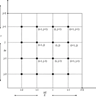
0,t hence are known from the boundary conditions.In Figure 2, ∆z & ∆r are constant mesh sizes along z and r directions re-spectively. We need an algorithm to find single values at next time level in terms of known values at an earlier time level. A forward difference approximation for the first order partial derivatives of T and C. And a central difference approxi-mation for the second order partial derivative of T and C are used. On intro-ducing finite difference approximations for:
For the purposes of coming up with a numerical solution for the problem, the radius of the capillary porous composite cylinder is 1.0
( )
2
1, 1, 1, 1 1, 1 ,
2 2
,
2 2
i j i j i j i j i j
i j
T T T T T
DOI: 10.4236/jcc.2019.77022 273 Journal of Computer and Communications
Figure 2. Finite difference grid for capillary porous composite cylinder.
( )
2
1, 1, 1, 1 1, 1 ,
2 2
,
2 2
i j i j i j i j i j
i j
T T T T T
T r r + − − + + + − − + − ∂ = ∂ ∆
( )
1, 1, 1, 1 1, 1
, 4
i j i j i j i j
i j
T T T T
T r r + − − + + + − − + ∂ = ∂ ∆
, 1 , , 1 , , 1 ,
, , ,
, ,
i j i j i j i j i j i j
i j i j i j
T T C C u u
T C u
t t t t t t
+ − + − + − ∂ ∂ ∂ = = = ∂ ∆ ∂ ∆ ∂ ∆
( )
1, 1, 1, 1 1, 1
, 4
i j i j i j i j
i j
C C C C
C t t + − − + + + − − + ∂ = ∂ ∆
( )
21, 1, 1, 1 1, 1 ,
2 2
,
2 2
i j i j i j i j i j
i j
C C C C C
C z z + − − + + + − − + − ∂ = ∂ ∆
( )
21, 1, 1, 1 1, 1
2 2
, 2
i j i j i j i j
i j
C C C C
C r r + − − + + + − − + ∂ = ∂ ∆
( )
1, 1, 1, 1 1, 1
, 4
i j i j i j i j
i j
C C C C
C r r + − − + + + − − + ∂ = ∂ ∆
DOI: 10.4236/jcc.2019.77022 274 Journal of Computer and Communications sides by
∆
t
and after simplifying, we let( )
2 1t r
z
∆ = =′
∆ (method is always stable and convergent), under this condition the above equations can be written as:
(
)
( )
( )
( )
(
)
, , , ,
2 2
2 2
1
2 2
i j i j i j i j
U V T C U V T C
C U V
t r r r z
+ − + + − +
∂ = + + +
∂ ∆ ∆ ∆
(
)
( )
( )
( )
(
)
, , , ,
2 2
2 2 2 2 2 2
1 2
2 2
i j i j i j i j
U V T C U V T C
T U V
t r r r z
+ − + + − +
∂ = + + +
∂ ∆ ∆ ∆
Let U T= i+1,j−Ti−1,j+Ti+1, 1j+ −Ti−1, 1j+ Let V =Ci+1,j−Ci−1,j+Ci+1, 1j+ −Ci−1, 1j+
4.3. Grid Structure and Plane of Heat and Mass Continuity
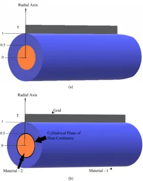
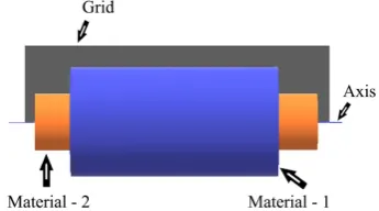
The plane of heat continuity is the cylindrical plane along the horizontal axis of the solid Figure 3(a) and Figure 3(b)) where the material properties change i.e. where the two different materials are joined or merged together. So, the grid po-sition in the above radially composite cylinder is as depicted in Figure 4.
(a)
[image:8.595.233.515.334.690.2](b)
Figure 3. (a) Plane of heat and mass continuity in a composite solid cylinder; (b) Grid
DOI: 10.4236/jcc.2019.77022 275 Journal of Computer and Communications
Figure 4. Grid position in a composite solid cylinder.
At this point of interface, i.e., the temperature at the last grid point along any radius of the first material is approximately equal to the temperature at the first grid point in the second material and similarly heat flux continuity is assumed. Similarly, the concentration at the last grid point along any radius of the first material is approximately equal to the concentration at the first grid point in the second material and similarly the concentration flux. So, the heat and mass con-tinuity equations can be written as follows:
(
)
(
)
1 , ,l 2 , ,0
T r z t =T r z t (10)
(
)
(
)
1 , ,l 2 , ,0
C r z t =C r z t (11)
The flux continuities can be similarly described.
5. Experimental Results and Discussion
5.1. Setup and Device Configuration
The experiment was executed using the CUDA Runtime Library, Quadro FX 4800 graphics card, Intel Core 2 Duo. The programming interface used was Vis-ual Studio.
The experiments were performed using a 64-bit Lenovo ThinkStation D20 with an Intel Xeon CPU E5520 with processor speed of 2.27 GHZ and physical RAM of 4.00 GB. The Graphics Processing Unit (GPU) used was an NVIDIA Quadro FX 4800 with the following specifications:
CUDA Driver Version: 3.0
Total amount of global memory: 1.59 Gbytes Number of multiprocessors: 24
Number of cores: 92
Total amount of constant memory: 65,536 bytes Total amount of shared memory per block: 16,384 bytes Total number of registers available per block: 16,384 Maximum number of threads per block: 512 Bandwidth:
Host to Device Bandwidth: 3412.1 (MB/s) Device to Host Bandwidth: 3189.4 (MB/s) Device to Device Bandwidth: 57,509.6 (MB/s)
condi-DOI: 10.4236/jcc.2019.77022 276 Journal of Computer and Communications tions of first kind using numerical methods. Our main purpose here was to ob-tain numerical solutions for Temperature T, and concentration C distributions across the various points in a capillary porous radially composite cylinder as heat and mass are transferred from one end of the capillary porous radially composite cylinder to the other. For our experiment, we compared the similarity of the CPU and GPU results. We also compared the performance of the CPU and GPU in terms of processing times of these results.
In the experimental setup, we are given the initial temperature T0 and
concen-tration C0 at point z = 0 on the capillary porous radially composite cylinder. Also,
there is a constant temperature and concentration N0 constantly working the
surface of the capillary porous radially composite cylinder. The temperature at the other end of the capillary porous radially composite cylinder where z = ∞ is assumed to be ambient temperature (assumed to be zero). Also, the concentra-tion at the other end of the capillary porous radially composite cylinder where z = ∞ is assumed to be negligible (≈0). Our initial problem was to derive the tem-perature T1 and concentration C1 associated with the initial temperature and
concentration respectively. We did this by employing the finite difference tech-nique. Hence, we obtained total initial temperature of (T0 + T1) and total initial
concentration of (C0 + C1) at z = 0. These total initial conditions were then used
to perform calculations.
For the purpose of implementation, we assumed a fixed length of 2L for the capillary porous radially composite cylinder and varied the number of nodal points N to be determined in the capillary porous radially composite cylinder. Since N is inversely proportional to the step size ∆z, increasing N decreases ∆z and therefore more accurate results are obtained with larger values of N. For easy implementation in Visual Studio, we employed the Forward Euler Method (FEM) for forward calculation of the temperature and concentration distribu-tions at each nodal point in both the CPU and GPU. For a given array of size N, the nodal points are calculated iteratively until the values of temperature and concentration become stable. In this experiment, we performed the iteration for 10 different time steps. After the tenth step, the values of the temperature and concentration became stable and are recorded. We ran the tests for several dif-ferent values of N and ∆z and the error between the GPU and CPU calculated results were increasingly smaller as N increased. Finally, our results were norma-lized in both the GPU and CPU.
5.2. Experimental Results
The normalized temperature and concentration distributions at various points in the capillary porous radially composite cylinder are depicted in Table 1 and
DOI: 10.4236/jcc.2019.77022 277 Journal of Computer and Communications
Table 1.Comparison of GPU and CPU results for capillary porous composite cylinder
(concentration).
Z CPU RESULTS GPU RESULTS
1 0.05102320 0.048674520
2 0.16001332 0.179985630
3 0.32310478 0.340000563
4 0.40124587 0.444023145
5 0.50029010 0.530001245
6 0.56310245 0.551212230
7 0.64102563 0.600102345
8 0.67502143 0.655201462
9 0.74001265 0.779856321
10 0.84420135 0.859874563
11 1 1
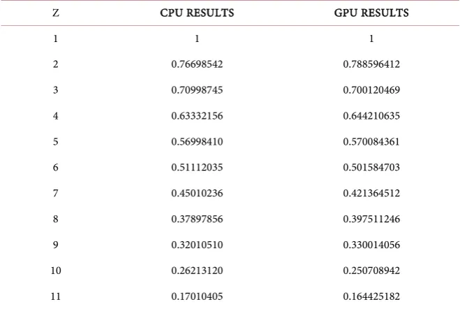
Table 2.Comparison of GPU and CPU results for capillary porous composite cylinder
(temperature).
Z CPU RESULTS GPU RESULTS
1 1 1
2 0.76698542 0.788596412
3 0.70998745 0.700120469
4 0.63332156 0.644210635
5 0.56998410 0.570084361
6 0.51112035 0.501584703
7 0.45010236 0.421364512
8 0.37897856 0.397511246
9 0.32010510 0.330014056
10 0.26213120 0.250708942
11 0.17010405 0.164425182
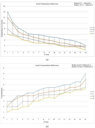
where the heat resource and mass resource are constantly applied. As we move away from this point, the values of the temperature decrease and concentration increase. At a point near the designated end of the capillary porous radially composite cylinder, the values of the temperature approach zero and concentra-tion approach one.
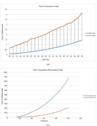
[image:11.595.209.539.368.589.2]DOI: 10.4236/jcc.2019.77022 278 Journal of Computer and Communications For the purpose of measuring the execution time, the same functions were im-plemented in both the device (GPU) and the host (CPU), to initialize the temper-ature and concentration and to compute the numerical solutions. In this case, we measured the processing time for different values of N. The graph in Figure 5
depicts the performance of the GPU versus the CPU in terms of the processing time. We ran the test for N running from 10 to 550 with increments of 30 and generally, the GPU performed the calculations a lot faster than the CPU.
- When N was smaller than 16, the CPU performed the calculations faster than the GPU.
- For N larger than 16 the GPU performance began to increase considerably.
Figure 6(a) and Figure 6(b) show some of our experimental results for both capillary porous radially composite cylinder.
(a)
[image:12.595.208.539.260.706.2](b)
DOI: 10.4236/jcc.2019.77022 279 Journal of Computer and Communications
(a)
[image:13.595.209.539.59.485.2](b)
Figure 6. (a) Performance of GPU and CPU implementations for capillary porous
compo-site cylinder; (b) Performance of GPU and CPU implementations for capillary porous composite cylinder with incremental number of nodes.
Finally, the accuracy of our numerical solution was dependent on the number of iterations we performed in calculating each nodal point, where more iteration means more accurate results. In our experiment, we observed that after 9 or 10 iterations, the solution to the heat and mass equation at a given point became stable. For optimal performance, and to keep the number of iterations the same for both CPU and GPU, we used 10 iterations and experimental results for ca-pillary porous radially composite cylinder show about 5 times speed-up
6. Conclusion and Future Work
DOI: 10.4236/jcc.2019.77022 280 Journal of Computer and Communications GPGPUs. Our conclusion shows that finite difference method is well suited for parallel programming. We implemented numerical solutions utilizing highly parallel computations capability of GPGPU on nVidia CUDA. We have demon-strated GPU can perform significantly faster than CPU in the field of numerical solution to heat and mass transfer. Experimental results for capillary porous ra-dially composite cylinder indicate that our GPU-based implementation shows a significant performance improvement over CPU-based implementation and the maximum observed speedups are about 10 times.
There are several avenues for future work. We would like to test our algorithm on different GPUs and explore the new performance opportunities offered by newer generations of GPUs. It would also be interesting to explore more tests with large-scale data set. Finally, further attempts will be made to explore more complicated problems both in terms of boundary and initial conditions as well as other geometries.
Conflicts of Interest
The authors declare no conflicts of interest regarding the publication of this pa-per.
References
[1] Owens, J.D., Luebke, D., Govindaraju, N., Harris, M., Krüger, J., Lefohn, A.E. Pur-cell, T.J. (2007) A Survey of General-Purpose Computation on Graphics Hardware.
Computer Graphics Forum, 26, 80-113.
https://doi.org/10.1111/j.1467-8659.2007.01012.x
[2] NVIDIA Corporation (2009) NVIDIA Programming Guide 2.3.
https://www.nvidia.com
[3] Luikov, A.V. (1966) Heat and Mass Transfer in Capillary Porous Bodies. Pergamon Press, Oxford, 233-303. https://doi.org/10.1016/B978-1-4832-0065-1.50010-6
[4] Narang, H.N. and Nekkanti, R.K. (2001) Wavelet-Based Solution to Time-Dependent Two-Point Initial Boundary Value Problems with Non-Periodic Boundary Conditions. Proceedings of the IATED International Conference Signal Processing, Pattern Recognition & Applications, Rhodes, Greece, 3-6 July 2001. [5] Narang, H.N. and Nekkanti, R.K. (2002) Wavelet-Based Solution of Boundary
Val-ue Problems Involving Hyperbolic Equations. Proceedings from the IATED Inter-national Conference Signal Processing, Pattern Recognition & Applications, Grete, Greece, 25-26 June 2002, 470-473.
[6] Narang, H. and Nekkanti, R. (2001) Wavelet-Based Solutions to Problems Involving Parabolic Equations. Proceedings of the IATED International Conference Signal Processing, Pattern Recognition & Applications, Rhodes, Greece, 3-6 July 2001. [7] Narang, H.N. and Nekkanti, R.K. (2002) Wavelet-Based Solution to Elliptic
Two-Point Boundary Value Problems with Non-Periodic Boundary Conditions.
Proceedings from the WSEAS International Conference in Signal, Speech, and Im-age Processing, Skiathos, Skiathos Island, Greece, 25-28 September 2002.
Com-DOI: 10.4236/jcc.2019.77022 281 Journal of Computer and Communications putation and Differential Equations, SCICADE 2003, Trondheim, Norway, 30 June-4 July 2003.
[9] Narang, H.N. and Nekkanti, R.K. (2004) Wavelet Based Solution to Time-Dependent Two Point Initial Boundary Value Problems with Non-Periodic Boundary Conditions Involving High Intensity Heat and Mass Transfer in Capillary Porous Bodies. IATED International Conference Proceedings, Rhodes, Greece, 30 June-2 July 2003, 130-135.
[10] Ambethkar, V. (2008) Numerical Solutions of Heat and Mass Transfer Effects of an Unsteady MHD Free Conective Flow Past an Iffinite Vertical Plate with Constant Suction. Journal of Naval Architecture and Marine Engineering, 5, 27-36.
[11] Krüger, J. and Westermann, R. (2003) Linear Algebra Operators for GPU Imple-mentation of Numerical Algorithms. ACM Transactions on Graphics, 22, 908-916.
https://doi.org/10.1145/882262.882363
[12] Bolz, J., Farmer, I., Grinspun, E. and Schröder, P. (2003) Sparse Matrix Solvers on the GPU: Conjugate Gradients and Multigrid. ACM Transactions on Graphics, 22, 917-924. https://doi.org/10.1145/882262.882364
[13] Goodnight, N., Woolley, C., Luebke, D. and Humphreys, G. (2003) A Multigrid Solver for Boundary Value Problems Using Programmable Graphics Hardware.
Proceeding of Graphics Hardware, San Diego, CA, 26-27 July 2003, 102-111. [14] Harris, M., Baxter, W., Scheuermann, T. and Lastra, A. (2003) Simulation of Cloud
Dynamics on Graphics Hardware. Proceeding of Graphics Hardware, San Diego, CA, 26-27 July 2003, 92-101.
[15] Harris, M. (2003) Real-Time Cloud Simulation and Rendering. Ph.D. Thesis, The University of North Carolina, Chapel Hill, NC.
[16] Kim, T. and Lin, M. (2003) Visual Simulation of Ice Crystal Growth. Proceedings of SIGGRAPH/Eurographics Symposium on Computer Amination, San Diego, CA, 26-27 July 2003, 86-97.
[17] Lefohn, A., Kniss, J., Hansen, C. and Whitaker, R. (2003) Interactive Deformation and Visualization of Level Set Surfaces Using Graphics Hardware. IEEE Visualiza-tion, Seattle, WA, 19-24 October 2003, 75-82.
[18] GPGPU Website. http://www.gpgpu.org
[19] Narang, H.N., Wu, F., Ogunniyan, A. and Mohammed, A.R. (2017) An Efficient Acceleration of Solving Heat and Mass Transfer Equations with Second Kind Boundary and Initial Conditions in Solid and Hollow Cylinder Using Programma-ble Graphics Hardware. Journal of Computations & Modellling, 7, 29-50.
[20] Narang, H.N., Wu, F. and Mohammed, A.R. (2017) An Efficient Solution of Heat and Mass Transfer Equations using Programmable General Purpose Processing Unit under Natural Boundary Conditions in Capillary Porous Solid and Hollow Cy-linder. International Advanced Research Journal in Science, Engineering and Technology, 4, 1-11.
![Figure 1. GPU memory architecture [2].](https://thumb-us.123doks.com/thumbv2/123dok_us/9010514.397764/4.595.212.537.72.475/figure-gpu-memory-architecture.webp)