PREPARATION, CHARACTERIZATION
1,*
Manjunath, N.K.,
1
Faculty
2
Assistant Professor, Department of Chemistry, Arbaminch University, Ethiopia
ARTICLE INFO ABSTRACT
Fuel cells are electrochemical devices that directly convert chemical energy to electrical energy. Among
electrolyte membrane (PEM
PEMFC stack the gas diffusion media is sandwiched between the bip
to form the gas diffusion layer (GDL). In the present study GDL macroporous layer were prepared using coir pith carbon fibers along with PVA as binder and Pani as co
of electrical resistivity
commercially available(SIGRACET 10, 24/25,34/35& TORAY GDL) GDL, the effect of binder, co binder and thickness of GDL were studied.
Copyright © 2018, Manjunath et al. This is an open access distribution, and reproduction in any medium, provided
INTRODUCTION
Fuel cells are environmentally safe, efficient, clean, quite and modular electrochemical devices consisting of an electrolyte medium sandwiched between two electrodes as anode and cathode. The Ions generated during oxidation or reduction are transported from one electrode to the other through the ionically conductive but electronically insulating electrolyte. The electrolyte also serves as a barrier between the fuel and oxidant.. The fuel and oxidant do not mix at any point hence combustion does not occurs. The fuel cell therefore is not limited by the Carnot efficiency. Theoretically fuel cell can yield 100% efficiency. However practically it is not satisfactory due to mixed potential at electrodes, activation losses, Ohmic losses and
Go = –nFEo,cell
Where n is the number of electrons transferred, F is Faraday’s constant (96,475 C/equiv). A PEMFC is unique in that it is the only kind of low temperature fuel cell that uses a solid electrolyte, usually a polymer electrolyte membrane (PEM Nafion®).
*Corresponding author: Manjunath, N.K.,
Faculty, National Institute of Technology, Trichy.
ISSN: 0975-833X
Vol. 10, Issue,
Article History:
Received 30th August, 2018
Received in revised form 07th September, 2018
Accepted 19th October, 2018
Published online 30th November, 2018
Citation: Manjunath, N.K., Ethiraj, J. and Karthikeyan M Ramasamy
pem fuel cell”, International Journal of Current Research Key Words:
PEMFC (polymer electrolyte membrane fuel cell), GDL (gas diffusion layer),
MaPL (macro porous layer), Pani (poly aniline), PVA (poly vinyl alcohol).
RESEARCH ARTICLE
PREPARATION, CHARACTERIZATION AND COMPARATIVE STUDY OF GAS DIFFUSION LAYER FOR
PEM FUEL CELL
Manjunath, N.K.,
2Ethiraj, J. and
2Karthikeyan M Ramasamy
Faculty
,National Institute of Technology, Trichy
Assistant Professor, Department of Chemistry, Arbaminch University, Ethiopia
ABSTRACT
Fuel cells are electrochemical devices that directly convert chemical energy to electrical energy. Among fuel cells PEMFC is unique and only kind of low temperature fuel cell that uses solid polymer electrolyte membrane (PEM - Nafion®) which operates at relatively low temperature (60
PEMFC stack the gas diffusion media is sandwiched between the bip
to form the gas diffusion layer (GDL). In the present study GDL macroporous layer were prepared using coir pith carbon fibers along with PVA as binder and Pani as co
of electrical resistivity and porosity of coir pith carbon fibers based GDL macroporous layer with commercially available(SIGRACET 10, 24/25,34/35& TORAY GDL) GDL, the effect of binder, co binder and thickness of GDL were studied.
access article distributed under the Creative Commons Attribution the original work is properly cited.
Fuel cells are environmentally safe, efficient, clean, quite and modular electrochemical devices consisting of an electrolyte medium sandwiched between two electrodes as anode and cathode. The Ions generated during oxidation or reduction are rom one electrode to the other through the ionically conductive but electronically insulating electrolyte. The electrolyte also serves as a barrier between the fuel and oxidant.. The fuel and oxidant do not mix at any point hence . The fuel cell therefore is not limited by the Carnot efficiency. Theoretically fuel cell can yield 100% efficiency. However practically it is not satisfactory due to mixed potential at electrodes, activation
Where n is the number of electrons transferred, F is Faraday’s constant (96,475 C/equiv). A PEMFC is unique in that it is the only kind of low temperature fuel cell that uses a solid electrolyte, usually a polymer electrolyte membrane
(PEM-PEFCs presently operate at relatively low temperatures (60 120°C; more toward the lower end of the range). The operating environment is kept well hydrated to maximize membrane conductivity. In a proton exchange membrane fuel cell (PEMFC) stack, the gas dif
between the bipolar plate and the catalyst layer to form the gas diffusion layer mass transport losses which cause overvoltage due to which the cell voltage output decreases with increasing current density. The standard free ener
overall reaction of the fuel cell is given by. In addition to the functions specified, the diffusion media must also be resistant to corrosion. The environment inside a PEMFC is typically very moist, acidic, and has high concentration
the anode. Most materials, particularly metal, are prone to corrosion in this type of environment. The requirements identified by Mathias, along with the need for stability in a corrosive environment, limit the options for materials which can be used as diffusion media in PEM fuel cells. Carbon fibers are the predominant materials used for the construction of gas diffusion media due to their resistance to corrosion and low electrical resistivity or high electrical conductivity. Generally carbon fibers used for preparation of GDL are polyacrylonitrile (PAN) , isotropic pitch and mesophase pitch based fibers usually are coal based or petroleum pitch based are relatively costlier and prone to exhaustion. In the present
International Journal of Current Research
Vol. 10, Issue, 11, pp.75435-75442, November, 2018
DOI: https://doi.org/10.24941/ijcr.33101.11.2018
Karthikeyan M Ramasamy. 2018. “Preparation, characterization and comparative study of gas diffusion layer for
International Journal of Current Research, 10, (11), 75435-75442.
COMPARATIVE STUDY OF GAS DIFFUSION LAYER FOR
Karthikeyan M Ramasamy
Assistant Professor, Department of Chemistry, Arbaminch University, Ethiopia
Fuel cells are electrochemical devices that directly convert chemical energy to electrical energy. fuel cells PEMFC is unique and only kind of low temperature fuel cell that uses solid polymer Nafion®) which operates at relatively low temperature (60-120°C). In PEMFC stack the gas diffusion media is sandwiched between the bipolar plate and the catalyst layer to form the gas diffusion layer (GDL). In the present study GDL macroporous layer were prepared using coir pith carbon fibers along with PVA as binder and Pani as co-binder. A comparative analysis and porosity of coir pith carbon fibers based GDL macroporous layer with commercially available(SIGRACET 10, 24/25,34/35& TORAY GDL) GDL, the effect of binder,
License, which permits unrestricted use,
PEFCs presently operate at relatively low temperatures (60-120°C; more toward the lower end of the range). The operating environment is kept well hydrated to maximize membrane In a proton exchange membrane fuel cell (PEMFC) stack, the gas diffusion media is sandwiched between the bipolar plate and the catalyst layer to form the gas diffusion layer mass transport losses which cause overvoltage due to which the cell voltage output decreases with increasing current density. The standard free energy change (Go) of the overall reaction of the fuel cell is given by. In addition to the functions specified, the diffusion media must also be resistant to corrosion. The environment inside a PEMFC is typically very moist, acidic, and has high concentration of hydrogen at the anode. Most materials, particularly metal, are prone to corrosion in this type of environment. The requirements identified by Mathias, along with the need for stability in a corrosive environment, limit the options for materials which an be used as diffusion media in PEM fuel cells. Carbon fibers are the predominant materials used for the construction of gas diffusion media due to their resistance to corrosion and low electrical resistivity or high electrical conductivity. rbon fibers used for preparation of GDL are polyacrylonitrile (PAN) , isotropic pitch and mesophase pitch based fibers usually are coal based or petroleum pitch based are relatively costlier and prone to exhaustion. In the present
OF CURRENT RESEARCH
study GDL prepared was from carbon fibers of low cost and globally available coir pith fibers which are renewable and inexhaustible source of carbon materials.(2 – 21)
CHARACTERIZATION
The carbon layers obtained were characterized for the following properties by the techniques mentioned
Resistivity by Four-point probe method
The surface resistivity of carbon layers was determined by four point probe method. The advantage of this method is that two additional probes measures the voltage potential of the material surface and do not carry any current. In this method the voltage potential v adjacent to a probe carrying current is given by (22-24)
V = ρI/ 2πr
Where ρ is the surface resistivity of a material of semi-infinite size, I is the current in the probe, and r is the distance between the voltage measurement and the current probe
Porosity by pycknometer
The porosity of carbon layer was determined using pycknometer were in the particle porosity, material density, particle density were calculated using the formula
Particle porosity; Ep =(V1-(W1/Qm))/V1
Material density; Qm=(W1/(V1-( W5W1))g.cm -3
(GDL). Mathias et al. (1) provided specific functions of the gas diffusion media of reactant permeability, product permeability, heat conduction, mechanical strength and low Electrical resistivity.
MATERIALS AND CHEMICALS
Coir pith, poly vinyl alcohol, poly aniline
EXPERIMENTAL METHODS
Preparation of Carbon Fibers: Coir pith fibers obtained were cleaned with abrasive paper. The fibers were of longitudinal shreds of sideways protrusions. These fibers were cut into short fibers of about 1cm long. Then they were placed in a closed silica crucible. The temperature of pyrolysis was varied from 7500C to 10000C. The duration of pyrolysis (30, 45, 60 minutes) was also varied and optimized.
Fabrication of gdl Macro Porous Layer: The extent of carbonization or graphitization of coir pith depends on the heating temperature and time. The resulted carbon fibers were chopped, grinded up to a suitable particle size or dimension (sufficiently big particle shows relatively low resistivity). A slurry of the carbon particles in polyvinyl alcohol was prepared, sonicated and stirred for half an hour. Small amount of water was added to make mixture less viscous and the slurry was poured on to a hot plate at temperature 900C to 1000C.After evaporation of water, the carbon paper is removed from the hot plate and kept for drying at 450C to 600C.The carbon paper was heated at 180 0C to 200 0C for an hour in an oven to produce the macro porous layer.
Fabrication of gdl macro porous layer using conductive polymer filler (Pani) as co-Binder: Freshly prepared Pani solution was added to the mixture of grinded carbon, and PVA. It was stirred well for proper mixing and the mixture was poured on to a hot plate maintained at temperature 600Cto 700C. (Pani decomposes above 800C). After the evaporation of water, the carbon paper is removed from the hot plate and allowed to dry at 450C to 600C for an hour. Macro Porouslayer with Pani was fabricated. Macro porous carbon layers were obtained at different pyrolysis temperature and duration.
Particle density; Qp=(W1/V1) g.cm -3
Where W1 is the weight of the sample taken and V1 is the volume of the wet sample.
RESULTS AND DISCUSSION
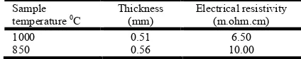
[image:2.595.325.537.436.478.2]Table-1,2,3 summaries the electrical resistivity and pyrolysis temperature of coir pith carbon fiber GDL at different temperature range and different time intervals with thickness(mm). Table-1 shows pyrolysis temperature maintained at 10000C and 8500C for 30 minutes. Similarly in Table 2 and table 3 temperature range are 8500C-9500C is maintained at 45 and 60 minutes. In Table-4 electrical resistivity and thickness of commercial GDL (SIGRACET 10 GDL) is shown for comparison. The electrical resistivity is low compared to commercial GDL at relatively lower thickness for different pyrolysis temperature and tine intervals.
Table 1.Variation of Resistivity of carbon layer pyrolysed at different temperatures for a period of 30 minutes
Sample temperature 0C
Thickness (mm)
Electrical resistivity (m.ohm.cm)
1000 0.51 6.50
[image:2.595.311.556.521.685.2]850 0.56 10.00
Table 2. Variation of resistivity of carbon layer pyrolysed at different temperatures for a period of 45 minutes
Sample temperature 0C
Thickness (mm)
Electrical resistivity (m.ohm.cm)
950 0.64 7.70
900 0.64 5.20
Fig. 1. Comparative study graph of electrical resistivity of coir pith carbon fiber GDL (pyrolysis of coir pith fibers for 60
minutes) with commercial GDL (Sigracet GDL 10)
Fig. 2. Comparative study graph of electrical resistivity of coir pith carbon fiber GDL (pyrolysis of coir pith fibers for 30
minutes) with commercial GDL (SIGRACET GDL 10)
Fig. 3. Comparative study graph of electrical resistivity of coir pith carbon fiber GDL (pyrolysis of coir pith fibers for 45
minutes) with commercial GDL (SIGRACET GDL 10)
Table-5 shows pyrolysis temperature maintained at 10000C, 9000C and 8500C for 30 minutes. Similarly in Table 6 and Table 7 temperature range are 8000C-9500C is maintained at 45 and 60 minutes. In Table-8, 9, 10 electrical resistivity and thickness of commercial GDL (SIGRACET 24/25,34/35& TORAY GDL) is shown for comparison. The electrical resistivity is low compared to commercial GDL at relatively lower thickness for different pyrolysis temperature and time intervals.
Table 5.Variation of resistivity of carbon layer pyrolysed at different temperatures for a period of 30 minutes using Pani
prepared from 0.2 M Aniline
Sample temperature 0C
Thickness (mm)
Electrical resistivity (m.ohm.cm)
1000 0.5 4.80
900 0.59 3.33
800 0.59 8.33
Table 6. Variation of resistivity of carbon layer pyrolysed at different temperatures for a period of 45 minutes using Pani
prepared from 0.2 M Aniline
Sample temperature 0C
Thickness (mm)
Electrical resistivity (m.ohm.cm)
950 0.5 2.22
900 0.45 6.30
850 0.5 7.90
800 0.6 5.90
Table-7. Variation of resistivity of carbon layer pyrolysed at different temperatures for a period of 60 minutes using Pani
prepared from 0.2 M Aniline
Sample temperature 0C
Thickness (mm)
Electrical resistivity (m.ohm.cm)
950 0.65 4.20
850 0.4 3.03
From Table 7 & Fig 4 coir pith GDL prepared using Pani (prepared from 0.2M aniline) as co-binder. The coir pith fibers pyrolysed at 8500C(relatively low temperature) for 60 minutes showed very low electrical resistivity(3.03 milli ohm.cm) at relatively lower thickness of GDL(0.4mm) which is the optimum temperature and time in comparison with Fig 5 & 6 (30, 45 minutes) along with commercial GDL.
Table 8.Electrical resistivity and thickness values of commercial sample SIGRACET GDL24/25
Thickness (mm) Electrical resistivity (m.ohm.cm)
0.75 <10
0.93 <12
0.75 <10
Table 9.Electrical resistivity and thickness values of commercial sample SIGRACET GDL34/35
Thickness (mm) Electrical resistivity (m.ohm.cm)
1.10 <11
1.24 <14
1.18 <12
1.27 <15
Table 10. Electrical resistivity and thickness values of commercial sample TORAY GDL
Thickness (mm) Electrical resistivity (m.ohm.cm)
0.19 5.8
0.28 5.6
0.37 4.7
Fig. 4. Comparative study graph of electrical resistivity of coir pith carbon fiber GDL prepared with Pani of 0.2M aniline (pyrolysis of coir pith fibers for 60 minutes) with commercial
GDL (TORAY GDL)
Fig. 5. Comparative study graph of electrical resistivity of coir pith carbon fiber GDL prepared with Pani of 0.2M aniline (pyrolysis of coir pith fibers for 30 minutes) with commercial
Fig. 6. Comparative study graph of electrical resistivity of coir pith carbon fiber GDL prepared with Pani of 0.2M aniline (pyrolysis of coir pith fibers for 45 minutes) with commercial GDL
[image:4.595.312.557.189.303.2](SIGRACET GDL 24/25&34/35)
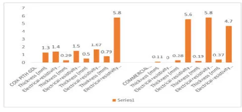
Table-11, 12 summaries the electrical resistivity and pyrolysis temperature of coir pith carbon fiber GDL using Pani (prepared from 0.4M aniline) as co-binder at different temperature range and different time intervals with thickness (mm). Table-11 shows pyrolysis temperature maintained at 9500C, 9000C for 30 minutes. Similarly in Table 12 temperature range are 8000C-10000C is maintained at 45 minutes. In Table- 10 electrical resistivity and thickness of commercial GDL (TORAY GDL) is shown for comparison. The electrical resistivity is low compared to commercial GDL at relatively comparable or high thickness for different pyrolysis temperature and time intervals. From Table 12 & Fig 7 coir pith GDL prepared using Pani (prepared from 0.4M aniline) as co-binder. The coir pith fibers pyrolysed at 9500C, 10000C for 45 minutes showed very low electrical resistivity(1.5milli ohm.cm) at relatively lower thickness of GDL(0.29mm) and 1.4 milli.ohm.cm resistivity at relatively high thickness of 1.3mm respectively which is the optimum temperature and time in comparison with Fig 8 (30minutes) along with commercial GDL
Table 11.Variation of resistivity of carbon layer pyrolysed at different temperatures for a period of 30 minutes using Pani
prepared from 0.4 M Aniline
Sample temperature
0C
Thickness (mm)
Electrical resistivity
(m.ohm.cm)
950 0.45 2.50
[image:4.595.311.555.360.481.2]900 0.45 7.10
Table 12. Variation of resistivity of carbon layer pyrolysed at different temperatures for a period of 45 minutes using Pani
prepared from 0.4 M Aniline
Sample temperature 0C
Thickness (mm)
Electrical resistivity (m.ohm.cm)
1000 1.3 1.40
950 0.29 1.50
900 0.50 1.67
850 0.79 5.80
Table-13 summarizes effect of variation of PVA binder on resistivity. Lower percentage of the binder (6.5%-8.0%) resulted in low resistivity or good conductivity. The higher percentages incorporate resistivity to the sample due to the non-conducting nature of PVA while lesser percentage than 6.5% provides poor binding. Table-14 & Fig 9 summarizes effect of variation of PVA binder and Pani on resistivity for carbon layers. It was observed that the increase of conducting
Pani decreases the resistivity of carbon layer and less PVA% (<6%) or poor binding have significant effect on the resistivity of carbon layer (increase in resistivity observed) even in presence of Pani. Table-15 summarizes effect of variation of thickness on resistivity for carbon layers. It was observed that the decrease in thickness (removing the polymer layer using salt paper, decreasing the roughness of surface) decreases the resistivity of carbon layer (0.18mm-5milli.mho.cm). The conductivity or resistivity of GDL is expected to be depends on the structure of polymer binder, content and distribution of conducting filler in polymer matrix at that particular thickness.
Fig. 7. Comparative study graph of electrical resistivity of coir pith carbon fiber GDL prepared with Pani of 0.4M aniline (pyrolysis of coir pith fibers for 45 minutes) with commercial
[image:4.595.41.281.536.579.2]GDL (TORAY GDL)
Fig. 8. Comparative study graph of electrical resistivity of coir pith carbon fiber GDL prepared with Pani of 0.4M aniline (pyrolysis of coir pith fibers for 30 minutes) with commercial
[image:4.595.319.545.568.638.2]GDL (TORAY GDL)
Table 13. Effect of variation of PVA binder on electrical resistivity
PVA% Thickness (mm) Resistivity (m.ohm.cm)
<6 0.34 15.4
6.5 0.34 9.50
7 0.33 10.00
8 0.35 5.60
9 0.33 20.00
[image:4.595.39.285.631.693.2]12 0.34 33.33
Table 14. Effect of variation of PVA binder and Pani on resistivity for carbon layers pyrolysed at 950oC temperatures and
for a period of 45 minutes
Sample Temperature 0C
PVA% Pani prepared from
aniline concentration (M)
resistivity (m.ohm.cm)
950 <6.0 0.1 14.30
950 6.5 0.2 2.50
950 6.5 0.4 1.54
[image:4.595.308.555.691.743.2]In Table – 17, 18 & Fig 10 depicts comparative study of porosity of coir pith GDL with commercial GDL. Table 17, 18 & Fig 10 it could be observed that coir pith GDL showed less and comparable porosity than commercial GDL (SIGRACET GDL 10, 24/25, 34/35 & TORAY GDL). From Tabel 19, 20, 21, 22 & Fig 11, 12 it could be observed that coir pith carbon fiber GDL with Pani showed comparable and equal porosity with commercial GDL.
Fig 13 summarizes Comparative study of thickness, material density and porosity of coir pith GDL with commercial GDL. From Fig 13 it could be observed that Pani based coir pith GDL showed equal and comparable porosity as same as commercial GDL at relatively high material density of coir pith GDL.This could be due to the space filling ability of Pani to penetrate results in the formation of open pores in the carbon layer and its tendency to increase the surface area.
[image:5.595.132.477.158.297.2]Fig. 9. Effect of variation of PVA binder and Pani on resistivity for carbon layers
Table 15. Effect of variation of thickness on resistivity for carbon layers pyrolysed at 950oC temperatures and for a period of 45 minutes and using Pani prepared from 0.2M aniline
Sample Temperature 0C PVA% Thickness (mm) Resistivity (m.ohm.cm)
950 9 0.70 13.9
950 9 0.60 10.40
950 9 0.44 7.70
[image:5.595.141.468.349.400.2]950 9 0.18 5.00
Table 16. Commercially Available Carbon Papers & Their Properties
Name of sample Thickness(mm) Material density(gcm-3) Porosity %
SIGRACET GDL10 1.57 1.63 1.63 -- 88 84 82
SIGRACET GDL 24/25 0.75 0.93 0.75 -- 84 76 88
SIGRACET GDL 34/35 1.1 1.24 1.18 -- 83 75 90
TORAY GDL 0.11 0.19 0.28 0.40 0.44 0.44 80 78 78
TORAY GDL 0.30 0.45 77
KUREHA E-715 0.35 0.35 TO 0.40 60 TO 80
[image:5.595.90.514.432.510.2]SPECTRACRAB 0.25 0.40 60 TO 80
Table 17. Effect of temperature of pyrolysis on material density & particle porosity for a period of 30 minutes
Sample Temperature 0C Thickness(mm) Material density(gm.cm-3) Particle porosity %
1000 0.51 0.217 35.7
900 0.61 0.645 69.0
850 0.56 0.284 42.5
[image:5.595.121.486.546.599.2]800 1.17 0.534 63.6
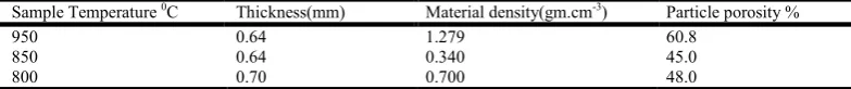
Table 18. Effect of temperature of pyrolysis on material density & particle porosity a period of 45 minutes
Sample Temperature 0C Thickness(mm) Material density(gm.cm-3) Particle porosity %
950 0.64 1.279 60.8
850 0.64 0.340 45.0
[image:5.595.107.499.631.672.2]800 0.70 0.700 48.0
Table 19. Effect of temperature of pyrolysis on material density & particle porosity a period of 30 minutes and using pani prepared from 0.2M aniline
Sample Temperature 0C Thickness(mm) Material density(gm.cm-3) Particle porosity %
1000 0.5 0.756 57.7
950 0.5 0.394 55.7
900 0.59 1.260 68.7
850 0.69 1.176 78.7
[image:5.595.91.518.716.792.2]Fig. 10. Comparative study graph of POROSITY & THICKNESS of coir pith carbon fiber GDL (pyrolysis of coir pith fibers for 30, 45 minutes) with commercial GDL (SIGRACET GDL 10, 24/25, 34/35 & TORAY GDL)
Table 20. Effect of temperature of pyrolysis on material density & particle porosity a period of 45 minutes and using pani prepared from 0.2M aniline
Sample Temperature 0C Thickness(mm) Material density(gm.cm-3) Particle porosity %
950 0.5 0.788 75.9
900 0.45 0.741 76.7
[image:6.595.107.491.415.595.2]800 0.6 1.470 85.0
Fig. 11. Comparative study graph of POROSITY & THICKNESS of coir pith carbon fiber GDL prepared with Pani of 0.2M aniline (pyrolysis of coir pith fibers for 30, 45 minutes) with commercial GDL (SIGRACET GDL 10, 24/25, 34/35 & TORAY GDL)
Table 21. Effect of temperature of pyrolysis on material density & particle porosity a period of 30 minutes and using pani prepared from 0.4 M aniline
Sample Temperature 0C Thickness(mm) Material density(gm.cm-3) Particle porosity %
1000 0.45 0.770 68.1
900 0.45 1.190 76.1
850 0.45 1.315 81.0
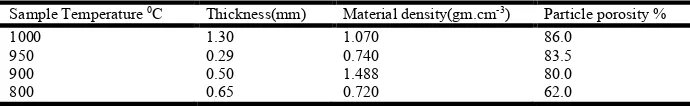
Table-22. Effect of temperature of pyrolysis on material density & particle porosity a period of 45 minutes and using pani prepared from 0.4 M aniline
Sample Temperature 0C Thickness(mm) Material density(gm.cm-3) Particle porosity %
1000 1.30 1.070 86.0
950 0.29 0.740 83.5
900 0.50 1.488 80.0
[image:6.595.117.480.641.683.2] [image:6.595.126.471.726.779.2]Conclusion
In the present study, we have chosen coir pith fibres which are cheap and globally available material as a source of carbon fibres to prepare GDL for PEMFC. GDL samples of coir pith with Pani (prepared from 0.2M, 0.4Maniline) as co-binder showed very low electrical resistivity AT RELATIVELY lower GDL thickness comparing with commercial GDL (SIGRACET GDL 10, 24/25, 34/35 & TORAY GDL). Porosity of coir pith GDL without pani showed less porosity. Coir pith GDL with Pani as co-binder showed comparable and equal porosity as same as commercial GDL at relatively lower thickness and high material density. Ultimately cost effective coir pith carbon fiber GDL samples with Pani as co-binder were prepared and these samples possess low electrical resistivity and comparable porosity, equal porosity with reference to commercial GDL. This may be due to physicochemical structure of polymer binder and conducting filler, content and distribution of filler in polymer matrix, shape and size of conductive filler particles as well as the processing method and conditions which shows good lower electrical resistivity. High porosity of Pani based GDL could be due to the space filling ability of Pani to penetrate results in the formation of open pores in the carbon layer and its tendency to increase the surface area.
Further work is in progress which involves preparation of GDL by varying sample temperature, thickness of carbon layer(mm), varying type & percentage of binder and co-binder (PVA, Pani) respectively and study of characteristic properties of GDL for PEM fuel cells.
REFERENCES
Coppo, M. Siegel, N.P. and vonSpakovsky, M.R. 2005. "On the Influence of Temperature on PEM Fuel Cell Operation," Journal of Power Sources, In Press.
Heinzel, A., Nolte, R., Ledjeff-Hey, K. and Zedda, M. 1998. "Membrane fuel cells - concepts and system design,"
Electrochimica Acta, Vol 43:24, PP 3817-3820.
Lim, C. and Wang, C. Y. 2004. "Effects of hydrophobic polymer content in GDL on power performance of a PEM fuel cell," Electrochimica Acta, vol 49:24, PP 4149-4156., (2004).
Mathias, M., J. Roth, J. Fleming, and W. Lehnert, 2003. “Diffusion media materials and characterization,"
Handbook of Fuel Cells: Volume 3 - Fuel Cell Technology
[image:7.595.85.507.51.243.2]and Applications, John Wiley & Sons.
Fig. 12. Comparative study graph of POROSITY & THICKNESS of coir pith carbon fiber GDL prepared with Pani of 0.4M aniline (pyrolysis of coir pith fibers for 30, 45 minutes) with commercial GDL (SIGRACET GDL 10, 24/25, 34/35 & TORAY GDL)
[image:7.595.116.482.280.491.2]Merida, W. R., McLean, G. and Djilali, N., 2001. "Non-planar architecture for proton exchange membrane fuel cells,"
Journal of Power Sources, Vol102:1-2, PP 178-185.
Passalacqua, E., Lufrano, F., Squadrito, G., Patti, A. and L. Giorgi, 1998. "Influence of the structure in low-Pt loading electrodes for polymer electrolyte fuel cells,"
Electrochimica Acta, Vol43:24, PP 3665-3673.
Prasanna, M., Ha, H.Y., Cho, E.A., Hong, S.A. and Oh, I. H. 2004. "Influence of cathode gas diffusion media on the performance of the PEMFCs," Journal of Power Sources, Vol 131:1-2, PP 147-154.
Song, J.M., Cha, S.Y. and Lee, W.M. 2001. "Optimal composition of polymer electrolyte fuel cell electrodes determined by the AC impedance method," Journal of
Power Sources, Vol94:1, PP 78-84.
Williams, M. V., Begg, E., Bonville, L., Kunz, H.R. and Fenton, J.M. 2004. "Characterization of gas diffusion layers for PEMFC," Journal of the Electrochemical
Society, Vol151:8, PP A1173-A1180.