Electron Microscopy Study of Eutectic Structure in Nb-Ti-X
and Nb-Zr-X (X = Co, Ni) Hydrogen Permeation Alloys
Mitsuhiro Matsuda
1, Takuya Murasaki
1, Minoru Nishida
2, Kazuhiro Ishikawa
3and Kiyoshi Aoki
31
Department of Materials Science and Engineering, Kumamoto University, Kumamoto 860-8555, Japan
2Department of Applied Science for Electronics and Materials, Kyushu University, Kasuga 816-8580, Japan 3Department of Materials Science, Kitami Institute of Technology, Kitami 090-8507, Japan
The morphology and crystallography of eutectic structures in several niobium-bearing hydrogen permeation alloys such as Nb20Ti40Ni40,
Nb30Ti35Co35, Nb13Zr43Ni44, and Nb25Zr35Co40 have been investigated by means of transmission electron microscopy. The alloys
Nb20Ti40Ni40, Nb30Ti35Co35, and Nb25Zr35Co40possess eutectic structures consisting of fine lamellar morphology with Nb-based bcc and B2
intermetallic phases. The Nb13Zr43Ni44alloy possesses a eutectic structure consisting of rod-shaped bcc-(Nb, Zr) phase and B33-ZrNi phase
which displacively transforms from the B2 high-temperature phase. The eutectic structures in the Nb20Ti40Ni40and the Nb25Zr35Co40alloys
exhibit a cube-on-cube orientation relationship between the bcc and B2 phases. The eutectic structure in the Nb13Zr43Ni44alloy also exhibits a
cube-on-cube orientation relationship by considering the lattice correspondence between the B2 and the B33 structures. On the other hand, a unique orientation relationship is found out in the Nb30Ti35Co35alloy, as follows:ð110Þ(Nb, Ti)==ð110ÞTiCo,½2221(Nb, Ti)==½001TiCo. The atomic
arrangements at the eutectic interface are also discussed on the basis of high-resolution observations. [doi:10.2320/matertrans.MA200803]
(Received April 23, 2008; Accepted May 20, 2008; Published July 2, 2008)
Keywords: eutectic structure, niobium-bearing alloy, transmission electron microscopy, orientation relationship
1. Introduction
Pd-Ag alloys have been commercially used as hydrogen permeation membranes for separating and purifying hydro-gen gas. Since Pd is too expensive and scarce in resources, it is desirable to develop non-Pd-based hydrogen permeation alloys with low cost and high performance. From the viewpoint of the hydrogen permeability for this demand, group 5A metals such as V, Nb, and Ta are promising candidates, because the hydrogen permeability of such metals is higher than those of Pd and Pd-Ag alloys.1–3) However, since these metals suffer from severe hydrogen embrittlement, they cannot be used as membranes at present. Recently, one of the authors found out that the Nb-Ti-Ni alloy consists of bcc-(Nb, Ti) + B2-TiNi eutectic micro-structures with an appropriate combination of high-hydrogen permeability and excellent hydrogen embrittlement resist-ance.4,5) The former property is attributable to the bcc-(Nb, Ti) phase, while the latter property is attributable to the B2-TiNi phase in the eutectic structure. On the basis of the same concept, Nb-Ti-Co,6) Nb-Zr-Ni7,8) and Nb-Zr-Co alloys have been developed as new hydrogen permeation materials. In these alloys, the eutectic structure is con-sidered to be valuable and indispensable in achieving the compatible properties. However, no study has yet focused on such eutectic microstructures, except for the Nb20Ti40Ni40 alloy.9,10)
The purpose of this paper is to clarify the morphology and crystallography of the eutectic structures in the four types of the Nb-bearing hydrogen permeation alloys, i.e., Nb20Ti40Ni40, Nb30Ti35Co35, Nb13Zr43Ni44, and Nb25 -Zr35Co40 by means of conventional transmission electron microscopy (CTEM). The atomic arrangements at the eutectic interface are also discussed on the basis of high-resolution transmission electron microscopy (HRTEM) observations.
2. Experimental Procedure
The eutectic alloys Nb20Ti40Ni40, Nb30Ti35Co35, Nb13 -Zr43Ni44, and Nb25Zr35Co40 (at%) were prepared from 99.9% Nb, 99.7% Ti, 99.9% Ni, 99.9% Co, and 99.9% Zr (% by mass) by arc melting in an argon atmosphere. The structural and microstructural examinations were carried out by using a X-ray diffractometer (XRD) and a scanning electron microscope (SEM), respectively. The TEM speci-mens were cut from the as-melted ingots and prepared by the argon ion milling technique. The CTEM and HRTEM observations were performed by using JEM-2000FX and FEI-Tecnai20F microscopes operated at 200 kV, respec-tively.
3. Results and Discussion
Figure 1 shows the XRD patterns of the four eutectic alloys. The Nb20Ti40Ni40 alloy consists of the bcc-(Nb, Ti) solid solution and B2-TiNi phase,4) as shown in Fig. 1(a). The lattice parameters of the (Nb,Ti) solid solution and Ti-Ni phase are calculated to be 0.329 nm and 0.302 nm, respectively. Although a near-equiatomic Ti-Ni alloy under-goes a thermoelastic martensitic transformation from the B2 to B19’ structure at approximately 373 K upon cooling,11) the TiNi phase in the eutectic Nb20Ti40Ni40 alloy possesses the B2 structure, as shown in Fig. 1(a). This occurs because the Ms point of the TiNi phase decreases below room temperature by the dissolution of a small amount of Nb in the Ti-Ni phase.12) Similarly, the Nb
30Ti35Co35 alloy con-sists of the bcc-(Nb, Ti) solid solution and B2-TiCo phase,6) as shown in Fig. 1(b). The lattice parameters of the (Nb, Ti) solid solution and TiCo phase are estimated to be 0.331 nm and 0.301 nm, respectively. The Nb13Zr43Ni44 alloy is composed of the bcc-(Nb, Zr) solid solution and B33-ZrNi phase with an orthorhombic cell,7,13)as shown in Fig. 1(c). Special Issue on Effectual Utilization of Hydrogen in Materials
The lattice parameters of the (Nb, Zr) solid solution and B-33 ZrNi phase are calculated to bea(Nb,Zr)¼0:332nm and aZrNi¼0:329nm, bZrNi¼0:998nm cZrNi¼0:406nm, re-spectively. The Bragg peaks on the Nb25Zr35Co40 alloy are indexed on the basis of the bcc-(Nb, Zr) solid solution and B2-ZrCo phase, except for the unknown Bragg peaks, as shown in Fig. 1(d). The lattice parameters of the (Nb, Zr) solid solution and ZrCo phase are estimated to be 0.332 nm and 0.319 nm, respectively.
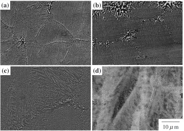
In order to investigate the microstructure of each eutectic alloy, SEM observations are carried out as shown in Fig. 2. The Nb20Ti40Ni40, Nb30Ti35Co35, and Nb25Zr35Co40 alloys possess eutectic structures with a fine lamellar morphology, as shown in Figs. 2(a), 2(b), and 2(d), respectively. The Nb13Zr43Ni44 alloy possesses a eutectic structure with lamellar and granular morphologies, as shown in Fig. 2(c). To clarify the morphology of such eutectic structures, SEM
observations of the longitudinal and vertical sections of the same part in the Nb13Zr43Ni44ingot are performed, as shown in Figs. 3(a) and 3(b). It is apparent that the Nb13Zr43Ni44 alloy consists of a rod-shaped structure. The results obtained from the XRD and SEM observations are summarized in Table 1. It has been recognized that the eutectic structure possesses a lamellar morphology when the volume fraction of the second phase is greater than 28%. While the rod-shaped morphology is observed for volume fractions less than 28%.14)Here, the volume fraction of the Nb-based bcc phase in the Nb20Ti40Ni40, Nb30Ti35Co35, and Nb25Zr35Co40 alloys are 33.3, 32.3, and 34.2%, respectively, as listed in Table 1. On the other hand, the volume fraction of the (Nb, Zr) solid solution in the Nb13Zr43Ni44 alloy is 21.9%. Therefore, the Nb13Zr43Ni44alloy consists of the rod-shaped eutectic structure, as apparent from the abovementioned criteria.
(a)
(b)
(c)
(d)
10
µ
m
Fig. 2 SEM images of the (a) Nb20Ti40Ni40, (b) Nb30Ti35Co35, (c) Nb13Zr43Ni44, and (d) Nb25Zr35Co40eutectic alloys.
5µm
(a)
(b)
Fig. 3 SEM images of the (a) longitudinal and (b) vertical section of the same part in the Nb13Zr43Ni44ingot, showing the rod-shaped structure.
Intensity (a.u.)
Diffraction angle, 2θ/
30 40 60 70
(a)
(b)
(c)
(d)
bcc
B2 B33unknown
50 80
°
Fig. 1 XRD patterns of the (a) Nb20Ti40Ni40, (b) Nb30Ti35Co35, (c)
[image:2.595.57.280.70.238.2] [image:2.595.305.546.72.222.2] [image:2.595.117.480.289.547.2]CTEM observations are performed to clarify in detail the crystallography of the eutectic structure. Figures 4(a) and 4(b) show the typical bright field image and the correspond-ing electron diffraction pattern of the Nb20Ti40Ni40 alloy, respectively. From the pattern shown in Fig. 4(b) and the dark field image obtained using 100TiNi reflection, it is identified that the thicker lamellas correspond to the B2-TiNi phase, whereas the thinner lamellas correspond to the bcc-(Nb, Ti) phase. The thickness of the bcc-(Nb, Ti) phase varies
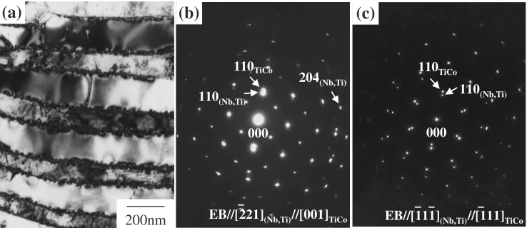
[image:3.595.49.550.84.205.2]from 40 to 60 nm and that of the TiNi phase varies from 100 to 200 nm. The orientation relationship between the (Nb, Ti) and the TiNi phases is determined as follows:½001(Nb,Ti)== ½001TiNi, ð100Þ(Nb,Ti)==ð100ÞTiNi, ð010Þ(Nb,Ti)==ð010ÞTiNi, that is, the cube-on-cube orientation relationship is main-tained between the two phases. The interface plane between the two phases is determined as f110g(Nb,Ti)==f110gTiNi. Similar morphology and crystallography, i.e., the cube-on-cube relationship between the (Nb, Zr) and the ZrCo phase, are confirmed for the eutectic structure of the Nb25Zr35Co40 alloy. The thickness of the (Nb, Zr) phase varies from 30 to 60 nm and that of the ZrCo phase varies from 60 to 100 nm. Figure 5 shows the typical bright field image and the corresponding electron diffraction patterns of the eutectic structure in the Nb30Ti35Co35 alloy. The thinner lamellas with widths ranging from 80 to 100 nm correspond to the bcc-(Nb, Ti) phase, and the thicker lamellas with widths ranging from 150 to 200 nm correspond to the B2-TiCo phase. It must be noted that the orientation relationship between the the bcc-(Nb, Ti) and B2-TiCo phases is determined to be ½2221(Nb,Ti)==½001TiCo, ð110Þ(Nb,Ti)==ð110ÞTiCo. This rela-tionship is invariant, even for specimens annealed at 1173 K for 360 ks. However, it is apparent that the interface is parallel to f110g(Nb,Ti) and f110gTiNi, similar to that in the Nb20Ti40Ni40 alloy. This fact indicates that the two phases relatively rotate approximately 70around the common (110) plane from the cube-on-cube orientation relationship. So far as we know, this relationship is quite unique in the eutectic Table 1 Characteristics of the eutectic structure in the four niobium-bearing alloys.
Nb20Ti40Ni40 Nb30Ti35Co35 Nb13Zr43Ni44 Nb25Zr35Co40
Morphology lamellar lamellar rod lamellar
Nb-based phase lattice parameter (nm)
bcc-(Nb, Ti)
a¼0:329
bcc-(Nb, Ti)
a¼0:331
bcc-(Nb, Zr)
a¼0:332
bcc-(Nb, Zr)
a¼0:332
Volume fraction of
Nb-based phase (%) 33.3 32.3 21.9 34.2
Intermetallic phase lattice parameter (nm)
B2-TiNi
a¼0:302
B2-TiCo
a¼0:301
B33-ZrNi
a¼0:329 b¼0:998 c¼0:406
B2-ZrCo
a¼0:319
EB//[001](Nb,Ti)//[001]TiNi
000 100TiNi
200nm
110TiNi
110(Nb,Ti)
(a)
(b)
Fig. 4 (a) A bright field image and (b) the corresponding electron diffraction pattern of the Nb20Ti40Ni40 alloy from the ½001(Nb, Ti)==
½001TiNizone axis, showing the cube-on-cube orientation relationship.
200nm EB//[221](Nb,Ti)//[001]TiCo
000
204(Nb,Ti)
110TiCo
110(Nb,Ti)
(a)
(b)
(c)
000 110TiCo
110(Nb,Ti)
EB//[111](Nb,Ti)//[111]TiCo
Fig. 5 (a) A bright field image, (b) and (c) the corresponding electron diffraction patterns of the Nb30Ti35Co35 alloy from the
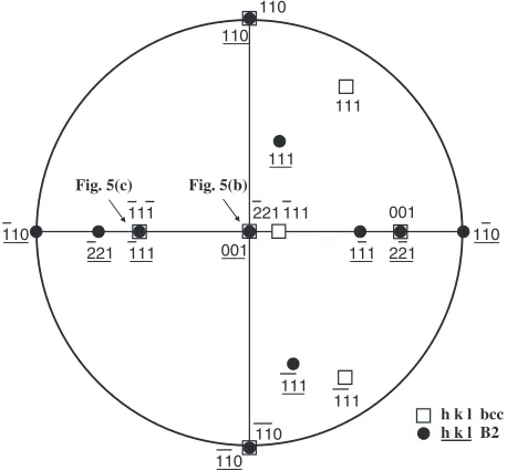
[image:3.595.47.291.241.399.2] [image:3.595.114.483.597.757.2]structure consisting of the bcc and B2 phases.15)The strain contrast along the interface in the Nb30Ti35Co35alloy is more complex as compared to that in the Nb20Ti40Ni40alloy, which is probably due to the different orientation relationship. This will be discussed later in the HRTEM observations. For satisfying this orientation relationship, the direction along which the eutectic interface is observed in the edge-on state from the low index zone axis of both the phases is only ½11111(Nb,Ti)==½1111TiCo, as shown in the stereographic pro-jection in Fig. 6. This fact is demonstrated in Fig. 5(c).
Figure 7(a) shows the typical bright field image of the Nb13Zr43Ni44 alloy. The electron diffraction patterns in Figs. 7(b) and 7(c) are obtained from the elliptical phase A, and those in (b0) and (c0) are obtained from the matrix region B. Since the patterns (b) and (c) are consistently indexed with the bcc structure ofa0¼0:332nm determined from the XRD experiment in Fig. 1(c), the elliptical phase A is identified as the (Nb, Zr) solid solution. The longitudinal section of the rod-like bcc phase is observed from another beam direction.
Therefore, the phase A with elliptical shape in Fig. 7(a) indicates the vertical section of the rod-like bcc phase; thus, the ½110bcc direction is considered to be parallel to the growth direction of the rod-like phase. These observations correspond to the SEM images in Figs. 2(c) and 3. On the other hand, the patterns (b0) and (c0) can be indexed by the B33 structure with orthorhombic unit cell, as mentioned above. It is apparent from these two pairs of patterns that crystallographic orientation relationships exist between the bcc-(Nb, Zr) and B33-ZrNi phases, as follows:ð1110Þ(Nb, Zr)== ð001ÞZrNi, ð001Þ(Nb, Zr)==ð100ÞZrNi, ð110Þ(Nb, Zr)==ð010ÞZrNi, ½110(Nb,Zr)==½010ZrNi, and ½001(Nb, Zr)==½100ZrNi. We have confirmed the existence of reversible endothermic peaks at approximately 1380 K and exothermic peaks at approximately 1300 K in the DTA heating and cooling curves, respectively. It has been reported that near-equia-tomic ZrPd alloys undergo martensitic transformation from the B2 to B33 structures.16)Therefore, we can assume that the ZrNi alloys as well as ZrPd alloys undergo martensitic transformation from the B2 to B33 structures. The lattice correspondence between the B2 parent and B33 martensitic phases is deduced as follows by considering the lattice parameters of both the structures: ½001B2==½100B33, ð110ÞB2==ð010ÞB33, and ð1110ÞB2==ð001ÞB33. The orientation relationship between the bcc-(Nb, Zr) phase and the B2 parent phase of ZrNi alloy is expressed as follows: ½001(Nb,Zr)==½001B2-ZrNi, ð110Þ(Nb,Zr)==ð110ÞB2-ZrNi, and ð1110Þ(Nb,Zr)==ð1110ÞB2-ZrNi, that is, they satisfy the cube-on-cube relationship.
The orientation relationships of the eutectic structure in the four niobium-bearing alloys are summarized in Table 2. These observations provide that the eutectic structures in the Nb20Ti40Ni40, Nb13Zr43Ni44, and Nb25Zr35Co40 alloys possess the cube-on-cube relationship, while that in the Nb30Ti35Co35 alloy possesses a unique orientation relation-ship, i.e.,½2221(Nb,Ti)==½001TiCoandð110Þ(Nb,Ti)==ð110ÞTiCo. Ondaet al.have investigated the cube-on-cube interface in the Nb20Ti40Ni40 alloy by using HRTEM observations and Ballman’s O-lattice theory.9)There exist misfit dislocations ofb¼1=2½1111TiNior1=2½1111TiNiwith regular spacings of approximately 2.6 nm in the B2-TiNi phase. Since we also
110
111 111
h k l bcc h k l B2
110
001 221 111 110
221 111 111
111 221 001
110
110
110 111
111
Fig. 5(b) Fig. 5(c)
Fig. 6 Stereographic projection from the½2221bccand½001B2direction.
100nm
(a)
EB//[001](Nb,Zr) 000
200
EB//[100]ZrNi 000
001 020
(c)
(c’)
EB//[110](Nb,Zr) 000
110
EB//[010]ZrNi 000
001 100
(b)
(b’)
A
B
002 110
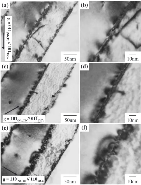
[image:4.595.54.283.75.288.2] [image:4.595.144.452.582.756.2]obtain the same results by the HRTEM observations, although we do not reproduce the micrograph here, only the unique eutectic interface in the Nb30Ti35Co35 alloy is discussed hereafter. Figure 8 shows the bright field images obtained from the ½11111(Nb, Ti)==½1111TiCo direction of the eutectic interface in the Nb30Ti35Co35 alloy. This direction corresponds to a unique condition in which the eutectic interface is in the edge-on state, observed from the low index zone axis of both the phases, as described in Figs. 5 and 6. In case of g¼011(Nb, Ti)==101TiCo and 1011(Nb, Ti)==0111TiCo, the periodic contrasts due to the misfit dislocations with the spacings of 1.5 to 1.8 nm are observed, as shown in Figs. 8(a) to 8(d). On the other hand, whengis110(Nb, Ti)==110TiCo, no contrast is observed, as shown in Figs. 8(e) and 8(f). The two-dimensional lattice image of the eutectic interface from the ½11111(Nb, Ti)==½1111TiCozone axis is presented in Fig. 9. The eutectic interface is almost parallel to the (110) plane of both the phases. We observe the extra half planes ofð101ÞTiCo on the eutectic interface, as indicated by the arrows. The
spacing between theð101ÞTiCoplane is of the order of 7–12 layers. This is consistent with the periodic contrasts shown in Fig. 8. In addition to the ð101ÞTiCo plane, we can also identify the extra half planes ofð110ÞTiCoalong the eutectic interface. Therefore, it is confirmed that the two types of misfit dislocations are coupled and arranged along the eutectic interface. The complex strain contrast along the interface is probably due to the two types of misfit dislocations. The characterizations such as determination of the Burgers vector of these dislocations have not yet been completed. This analysis is now in progress and will be reported in due course.
Final comments concern about the relationship between the hydrogen permeability and the interface structure. The hydrogen permeability of the Nb-Ti-Ni alloy increases with the volume fraction of the primary (Nb, Ti) phase.4,5) On the other hand, the Nb-Ti-Co alloy with the eutectic composition possesses the highest hydrogen permeability among all the Nb-Ti-Co ternary alloys.6)This indicates that hydrogen permeability depends on the alloy systems and their compositions. On the basis of the present microstruc-tural observations, the crystal, macro-, and micro-structures of the eutectic Nb-Ti-Ni alloy are similar to those of the eutectic Nb-Ti-Co alloy. However, the orientation relation-ship between both the alloys and their interface micro-structures are quite different. These facts suggest that the hydrogen permeation is probably influenced by the interface microstructure.
4. Conclusions
[image:5.595.45.549.85.136.2]The morphology and crystallography of the eutectic structures in several niobium-bearing hydrogen permeation Table 2 Orientation relationship between the two phases of the eutectic structure in the four niobium-bearing alloys.
Nb20Ti40Ni40 Nb30Ti35Co35 Nb13Zr43Ni44 Nb25Zr35Co40
Orientation ½001(Nb,Ti)==½001TiNi
½2221(Nb,Ti)==½001TiCo
½001(Nb,Zr)==½100B33-ZrNi==½001B2-ZrNi ½001(Nb,Zr)==½001ZrCo
relationship of the ð100Þ(Nb,Ti)==ð100ÞTiNi
ð110Þ(Nb,Ti)==ð110ÞTiCo
ð110Þ(Nb,Zr)==ð010ÞB33-ZrNi==ð110ÞB2-ZrNi ð100Þ(Nb,Zr)==ð100ÞZrCo
eutectic structure ð010Þ(Nb,Ti)==ð010ÞTiNi ð1110Þ(Nb,Zr)==ð001ÞB33-ZrNi==ð1110ÞB2-ZrNi ð010Þ(Nb,Zr)==ð010ÞZrCo
50nm
(a) (b)
(c) (d)
10nm
50nm
50nm
(e) (f)
10nm
10nm
g = 011
(Nb,T
i)// 101
T
iCo
g = 101(Nb,Ti) // 011TiCo
g = 110(Nb,Ti) // 110TiCo
Fig. 8 (a), (c), and (e) Bright field images of the eutectic interface in the Nb30Ti35Co35 alloy, obtained for g¼011(Nb, Ti)==101TiCo,
1011(Nb, Ti)==0111TiCo and110(Nb, Ti)==110TiCo, respectively. (b), (d), and
(f) Enlarged micrographs of the eutectic interface in (a), (c), and (e), respectively.
[image:5.595.304.549.161.341.2] [image:5.595.48.289.164.480.2]alloys such as Nb20Ti40Ni40, Nb30Ti35Co35, Nb13Zr43Ni44, and Nb25Zr35Co40 have been investigated by means of transmission electron microscopy. The atomic arrangements at the eutectic interface are also discussed on the basis of high-resolution observations. The obtained results are sum-marized as follows.
(1) The Nb20Ti40Ni40, Nb30Ti35Co35, and Nb25Zr35Co40 alloys have eutectic structures consisting of fine lamellar morphology with Nb-based bcc and B2 intermetalic phases. The Nb13Zr43Ni44 alloy possesses a eutectic structure consisting of rod-shaped bcc-(Nb, Zr) and B33-ZrNi phases, which displacively trans-forms from the B2 high-temperature phase.
(2) The eutectic structure in the Nb20Ti40Ni40 and Nb25Zr35Co40 alloys exhibits a cube-on-cube orienta-tion relaorienta-tionship between the bcc and the B2 phases. The eutectic structure in the Nb13Zr43Ni44 also exhibits the cube-on-cube orientation relationship by considering the lattice correspondence between the B2 and the B33 structures. On the other hand, a unique orientation relationship is found out in the Nb30 -Ti35Co35 alloy, as follows: ð110Þ(Nb, Ti)==ð110ÞTiCo and½2221(Nb, Ti)==½001TiCo.
(3) The strain contrast along the interface in the Nb30 -Ti35Co35 alloy is more complex as compared to that in the Nb20Ti40Ni40 alloy. This is due to the two types of misfit dislocations coupled and arranged along the eutectic interface.
Acknowledgements
This study was supported by a ‘‘Grant-in-Aid for Scientific Research (B)’’ from the Japanese Society for the Promotion
of Science (JSPS)’’ and ‘‘Grant-in-Aid for Young Scientists (B)’’ of the Ministry of Education, Culture, Sports, Science and Technology (MEXT), Japan. The authors would like to express their sincere appreciation to Prof. R. Tomoshige and Dr. S. Ii of Sojo University for their support in conducting the HRTEM experiments.
REFERENCES
1) C. Nishimura, M. Komaki and M. Amano: Mater. Trans., JIM 32
(1991) 501–507.
2) R. E. Buxbaum and T. L. Marker: J. Membrane Sci.85(1993) 29–38. 3) T. Ozaki, Y. Zhang, M. Komaki and C. Nishimura: Int. J. Hydrogen
Energy28(2003) 1229–1235.
4) K. Hashi, K. Ishikawa, T. Matsuda and K. Aoki: J. Alloys Compd.368
(2004) 215–220.
5) K. Hashi, K. Ishikawa, T. Matsuda and K. Aoki: Mater. Trans.46
(2005) 1026–1031.
6) K. Hashi, K. Ishikawa, T. Matsuda and K. Aoki: J. Alloys Compd.425
(2006) 284–290.
7) T. Takano, K. Ishikawa, T. Matsuda and K. Aoki: Mater. Trans.45
(2004) 3360–3362.
8) K. Ishikawa T. Takano, T. Matsuda and K. Aoki: Appl. Phys. Lett.87
(2005) 081906-1–081906-3.
9) T. Onda, M. Piao, Y. Bando, H. Ichinose and K. Otsuka: Mater. Trans., JIM36(1995) 23–29.
10) K. Kishida, Y. Yamaguchi, K. Tanaka, H. Inui, S. Tokui, K. Ishikawa and K. Aoki: Intermetallics.16(2008) 88–95.
11) K. Otsuka and X. Ren: Prog. Mater. Sci.50(2005) 511–678. 12) M. Piao, S. Miyazaki, K. Otsuka and N. Nishida: Mater. Trans., JIM33
(1992) 337–345.
13) M. E. Kirkpatrick, D. M. Bailey and J. F. Smith: Acta Cryst.15(1962) 252–255.
14) A. Hellawell: Met. Mater.1(1967) 361–368.
15) H. E. Cline and J. L. Walter: Metall. Trans.1(1970) 2907–2917. 16) L. A. Bendersky, J. K. Stalick, R. Portier and R. M. Waterstrat: