Structural and Compositional Modulation in Transformation
of LPSO Structure in Mg
97Zn
1Y
2Cast Alloys
Takanori Kiguchi
1, Yu Ninomiya
2,+, Kensuke Shimmi
2,+, Kazuhisa Sato
1and Toyohiko J. Konno
11Institute for Materials Research, Tohoku University, Sendai 980-8577, Japan
2Department of Materials Science, Graduate School of Engineering, Tohoku University, Sendai 980-8579, Japan
This study investigated modulation of the long period stacking order (LPSO) structure in aged Mg97Zn1Y2alloys using conventional
transmission electron microscopy (TEM) and aberration-corrected high-angle annular dark field-scanning transmission electron microscopy (HAADF-STEM). The irregular stacking sequence of a fragment of 24R-type LPSO acts as a catalyst for the transformation from 18R- to 14H-type LPSO. The elementary step of the transformation from 18R- to 24R-14H-type takes place by the ledge-pair movement on different (0001)Mg
planes with Shockley partial dislocations. Each ledge has a transition region in front of it. The transition regions are HCP-type stacking sequence with lower Zn and Y concentrations than those of the FCC-type enrichment layer. The solute elements migrate easily in the region, where solute elements produce a kind of diffusion field. Therefore, structural modulation occurs by a mechanism resembling diffusionaldisplacive transformation. Local strain analysis using HAADF-STEM images has elucidated that lattice spacing of (0001)Mgin the FCC-type enrichment
layer is shorter than that in the HCP-type transition region. These structural and compositional irregularities are an elementary step in the transformation of LPSO in Mg97Zn1Y2alloys. A diffusionaldisplacive type transformation mechanism in LPSO has been proposed.
[doi:10.2320/matertrans.MI201221]
(Received December 11, 2012; Accepted February 22, 2013; Published April 25, 2013)
Keywords: magnesium alloy, long-period stacking order (LPSO), diffusionaldisplacive transformation, ledge, aging
1. Introduction
Magnesium (Mg) based alloys are attractive as next-generation lightweight structural materials because of their low density, high-specific strength, damping capacity, recycling efficiency, and other features. Recently, it has been reported that a series of novel structures, with so-called “synchronized long period stacking order (LPSO)”in Mg TMRE (TM and RE respectively stand for transition and rare earth metals) alloy systems.1,2) Synchronized LPSO signifies the segregation of TM and RE elements into stacking faults and the long-range ordering of the segregated stacking faults.
The MgZnRE alloy with LPSO is divisible into two groups: type I (RE=Y, Dy, Ho, Er, Eu, Tm) and type II (RE=Gd, Tb). Particularly, Mg97Zn1Y2 alloy shows high
0.2%proof strength higher than 600 MPa and the elongation of 5%.1,2) The atomic level structure of the LPSO has been
examined by many researchers. Four polytypes, 10H, 14H, 18R and 24R, are found in the MgZnY alloy depending the thermal history and the solute concentration.38)
The structure of LPSOs has been clarified over the last three years. Zhu et al. propose a model structure of 18R-and 14H-type LPSOs in Mg96.7Zn0.8Y2.4Zr0.2 alloys. They
inferred a well-ordered arrangement of Zn and Y atoms.8) Yokobayashi et al. found that the completely ordered L12
-type structure in the orderdisorder -type LPSO structure in MgAlGd alloys.9)Recently, Egusaet al.showed a revised
crystalline structure of 18R- and 14H-type LPSO in Mg97Zn1RE2 (RE=Y, Er) and Mg85Zn6Y9 alloys.10) Based
on the diffuse scattering pattern in the electron diffraction patterns, they concluded that L12-type clusters align in
in-plane short range order. Therefore, LPSOs have the
medium-range and the short-medium-range ordering structure in each stacking fault as well as the long-range ordering one.
Mg97Zn1Y2alloys belong to the type I group. The type I
LPSO has already precipitated under the solidification process. As-cast alloys are in the non-equilibrium state. Then, the structural and the compositional modulation will show the transition state of the formation process of the LPSO structure. The formation and the growth mechanism have not been elucidated in a long time. Recently, Zhuet al.
proposed a transformation mechanism from 18R- to 14R-type LPSO structure in Mg96.7Zn0.8Y2.4Zr0.2 alloys.11) They also
showed that the 24R-type irregularity plays a role in the transformation. However, the compositional and structural modulation at a ledge has not been considered, nor has the sequential change of the LPSO with the 24R-type irregularity aged for different durations.
In this study, we specifically examined the transition state from the viewpoint of structural and compositional irregu-larity in the LPSO in Mg97Zn1Y2alloys. The structural and
compositional modulation of the LPSO structure through the 24R-type irregularity in Mg97Zn1Y2 alloys by aging for
different periods using a conventional transmission electron microscopy (TEM) and an aberration-corrected high-angle annular darkfield-scanning transmission electron microscopy (HAADF-STEM).
2. Experimental Procedure
The MgZnY alloy ingots were cast using high-frequency induction heating in an argon atmosphere. The nominal composition of the alloy used for this study is Mg97Zn1Y2
(at%). Specimens for aging treatment were cut from the master ingot using a diamond cutter. The specimens were aged at 773 K in the Ar atmosphere. They were then quenched in ice water. The respective aging times were 5, 10,
+Graduate Student, Tohoku University
Special Issue on Long-Period Stacking Ordered Structure and Its Related Materials (I)
30 and 50 h. Microstructural analyses of the alloys were conducted using transmission electron microscopy (TEM) with a point resolution of 0.18 nm (EM-002B, 200 kV; JEOL Ltd. (Topcon Corp.)) and an aberration-corrected scanning transmission electron microscope (STEM) with attainable resolution of less than 0.10 nm (JEM-ARM200F, 200 kV; JEOL Ltd.). The adjusted spherical aberration was about 5 µm. The convergent semi-angle was about 23 mrad. The collection semi-angle range of high angle annular dark field (HAADF)-STEM images was 90170 mrad. TEM specimens were cut from the aged specimens using electro-discharge machining. The shaped specimens are circular discs of 3 mmº©540 µmt. Discs were thinned using mechanical polishing followed by low-energy ion milling from 5 kV to 200 V (PIPS model691; Gatan Inc.). The HAADF-STEM images werefiltered using two-dimensional Wienerfiltering to improve the image quality without periodic artifacts (Filter Pro; HREM Research Inc.). Local strain analysis was conducted using peak-pair analysis (PPA) of HAADF-STEM images (PPA; HREM Research Inc.).12) The mask diameter was 5 pixels. Strictly speaking, a pair of basis vectors cannot be defined in the FCC/HCP stacking structure of LPSOs projected in the [2110]Mg direction. As a matter
of practical convenience, the basis vectors for measuring the lattice deformation were set to (228) and (22;10) in 18R-type LPSO structure.10) The reference area for the analysis was set to the HCP-type layer in the LPSO structure, i.e., the deformation of the enrichment layer against the non-enrichment layer.
3. Results
Figure 1 shows the following: (a), (d) bright field TEM images; (b), (e) selected area electron diffraction patterns (SADPs); and (c), (f ) intensity profiles of the SADPs along the c-axis of ¡-Mg matrix ([000l]Mg direction) of (b) an
as-cast, and (e) a 10 h aged alloys. The incidence directions of the electron beam are [4510]Mg vertical to the [000l]Mg. The
brightfield TEM (BFTEM) image of Fig. 1(a) shows that the LPSO has already formed in the as-cast alloy. Sharp line contrast of stacking faults between LPSO is also apparent. Figures 1(b) and 1(c) show that the LPSO of the as-cast alloy has extra diffraction spots of a series ofn/6(0002)Mg(nis an
integer). The LPSO is dominantly an 18R-type. The BFTEM image of Fig. 1(d) shows similar morphology of LPSO to that shown in Fig. 1(a). Figures 1(e) and 1(f ) show that the LPSO of 10 h aged alloy has extra diffraction spots of two sets of series of n/6(0002)Mg and n/7(0002)Mg (n is an
integer). These phases are 18R- and 14H-types. Here, both types of LPSO are comparable in terms of their extra spot intensities.
Figure 2 shows the following: (a), (d) bright field TEM images; (b), (e) selected area SADPs; and (c), (f ) intensity profiles of the SADPs along the c-axis of ¡-Mg matrix ([000l]Mg direction) of (a)(c) 30 h, and (d)(f ) 50 h-aged alloys. The incident directions of the electron beam are, respectively, [4510]Mg and [1010]Mg for (b) and (e). The
BFTEM image of Fig. 2(a) shows that sharp line contrast of stacking faults remains between LPSO, but the number is less than that shown in Figs. 1(a) and 1(d). Figures 2(b) and 2(c)
show that the LPSO of 30 h-aged alloy also has extra diffraction spots of two sets of series of n/6(0002)Mg and n/7(0002)Mg (n is an integer). Then these phases are
18R-and 14H-types. However, the 14H-type LPSO is dominant from the extra spot intensities unlike the image shown in Fig. 1(f ). The BFTEM image of Fig. 2(d) shows a barely remaining sharp line contrast of stacking faults between LPSO. Figures 2(e) and 2(f ) show that the LPSO of 50 h-aged alloy has only the extra diffraction spots of a series of n/7(0002)Mg (n is an integer). Then these phases are
dominantly 14H-types. The 50 h aging treatment is necessary to transform LPSO from the 18R- to the 14H-type at 773 K in the Ar atmosphere.
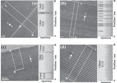
Figure 3 shows high-resolution transmission electron microscope (HRTEM) images with line profiles of the rectangular region in the images: (a) as-cast, (b) 10 h aged, (c) 30 h aged and (d) 50 h aged alloys. The as-cast alloy of Fig. 3(a) shows a single periodic array of the fringes, which is consistent with Fig. 1(b). The interval of the periodic fringes is 1.6 nm, which corresponds to that of 18R-type LPSO (1.56 nm).5,8) However, an irregular fringe (arrowed
position) is also observed. The interval of the irregular fringe is 2.1 nm, which corresponds to 24R-type LPSO (2.08 nm).5,8) The irregular fringe shows one-third part of
a unit cell of a 24R-type LPSO. Then, the irregular fringe
Fig. 1 (a), (d) Brightfield TEM images, (b), (e) selected area diffraction patterns (SADPs), and (c), (f ) intensity profiles of the SADPs along the
c-axis of¡-Mg matrix ([000l]Mgdirection): (a)(c) shows an as-casted and
[image:2.595.309.547.69.409.2]is not expected to reflect on the SADP as satellite spots in Fig. 1.
The 10 h-aged alloy of Fig. 3(b) shows two sets of periodic arrays of the fringes, which is consistent with Figs. 1(e) and 1(f ). The interval of the periodic fringes is 1.6 and 1.8 nm, which correspond to those of 18R- (1.56 nm) and 14H- (1.82 nm) type LPSO, respectively.5,8) Compared with Fig. 3(a), this means that 18R-type LPSO began transforming into 14H-type one under aging treatment conducted for less than 10 h at 773 K. The irregular fringes (arrowed positions) corresponding to 24R-type LPSO are also observed. Here, the 24R-type irregularity exists in or is bordered by the 14H-type LPSO, meaning that the 24R-type irregularity is expected to affect the transformation from 18R- to 14H-type LPSO.
The 30 h-aged alloy of Fig. 3(c) also shows two sets of periodic arrays of the fringes, which is consistent with Fig. 2(c). The interval of the periodic fringes is 1.6 and 1.8 nm, which corresponds to that of 18R- (1.56 nm) and 14H- (1.82 nm) type LPSO, respectively.5,8)Comparison with Fig. 3(b) reveals that 14H-type LPSO grows in 18R-type one under the aging treatment up to 30 h. The interface between the 18R- and 14H-type LPSOs seems very sharp and there is no irregularity. The 24R-type irregular fringe is not observed after 30 h-aged alloys in this experiment.
The 50 h-aged alloy of Fig. 3(d) shows the single periodic array of the fringes, which is consistent with Fig. 2(e). The interval of the periodic fringes is 1.8 nm, which corresponds to that of the 14H-type LPSO (1.82 nm).5,8)This means that
18R-type LPSO has transformed completely into 14H-type LPSO under aging treatment of up to 50 h at 773 K. The irregular fringe corresponding to 24R-type LPSO is not also
Fig. 2 (a), (d) Bright field TEM images, (b), (e) SADPs, and (c), (f ) intensity profiles of the SADPs along thec-axis of¡-Mg matrix ([000l]Mg
direction): (a)(c) shows 30 h, (d)(f ) 50 h aged alloys. The electron beam incidence direction is vertical to the [000l]Mgdirection.
[image:3.595.111.488.492.758.2]observed in this experiment. These results reflect that the 24R-type irregularity would only exist in 18R-type LPSO and the mixed type LPSO in the early stage of 773 K aging treatment. These facts imply that the 24R-type irregularity affects the transformation from 18R- to 14H-type LPSO.
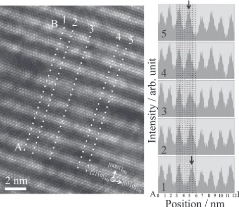
Figure 4 is a HAADF-STEM image of 773 K-5 h aged Mg97Zn1Y2. There are irregular points at which the spacing
of the enrichment layer changes. The arrow indicates a typical irregular point of LPSO where the enrichment layer shows ledge-like deformation. Figure 5 shows a HAADF-STEM image around the region indicated by an arrow in Fig. 4. The ledge-like transition region exists in the internal of 18R-type LPSO band. The Z2-contrast in the transition region spreads into the outside of the enrichment layer. The intensity profiles show line profiles of Z2-contrast along dotted lines Nos. 15. The enrichment layers away from the transition region (lines No. 1 and No. 5) show two strong peaks with one sub-peak on each side, which is a normal enrichment pattern.10) However, three strong peaks appear
with one sub-peak on each side along lines No. 2 and No. 4. Four weaker peaks appear with one sub-peak on each side on the center of the kink region (line No. 3). The intensity at the six-peaked region in the line No. 3 is weaker than that of the normal enrichment layers, which means the lower solute concentration.
Figure 6 shows a Bragg filtered HAADF-STEM image of Fig. 5. Open circles with a solid line indicate atomic columns of FCC-type stacking sequence. Those with a dotted line indicate atomic columns of HCP-type stacking sequence. A pair of Shockley partial dislocations with b=1/3[0110] and b=1/3[0110] exist at both sides of the HCP-type region. These partial dislocations indicate the existence of a pair of ledge structure. An intermediate region with HCP-type stacking sequence between the ledges, i.e., the transition region, shows weak Z2-contrast. The AA stacking
layer moves by the two closed-packed (0001)Mg planes
across the transition region; the stacking order locally
changes AA¼CA, C¼BA, A¼AAfrom left to right. Here, the AA, BA and CA denote the solute enrichment layers with different stacking planes in an FCC-type stacking sequence. The Z2-contrast of the transition region is lower than that
of the normal enrichment layer, meaning that the solute elements can migrate easily across (0001)Mg planes in the
[image:4.595.64.277.68.285.2]transition region. Therefore, the results show that the concentration of the solute elements is related with the stacking order change.
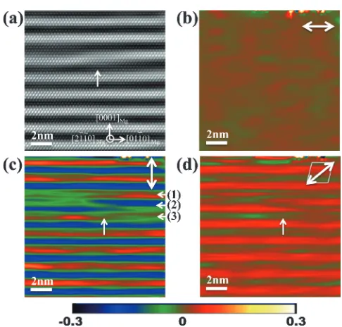
Figure 7 shows (a) an HAADF-STEM image and (b)(d) strain mapping around the transition region of an enrichment layer obtained from the PPA of the HAADF-STEM image Fig. 6(a). Figures 7(b)7(d) respectively show the in-plane normal strain, out-of plane normal strain, and simple shear strain. Here, the strain was measured relative to the lattice spacing of the non-enrichment layer. The in-plane normal strain map Fig. 7(b) shows homogeneous contrast with accuracy of«0.3%, which means that the interface between the enrichment layer and the non-enrichment layer is actually regarded as coherent. The out-of plane normal strain map
Fig. 4 HAADF-STEM image of 5 h aged Mg97Zn1Y2. The arrow indicates
a typical transition region of LPSO.
Fig. 5 HAADF-STEM image of 5 h aged Mg97Zn1Y2 alloy and line
profiles of the Z2-contrast of the image along the dotted line.
[image:4.595.307.544.71.276.2] [image:4.595.312.539.330.466.2]Fig. 7(c) shows that the lattice spacing of the enrichment layer is much smaller than that of the non-enrichment layer. The strain irregularities are limited to within the enrichment layer including a transition region (layer (2)) and the neighboring two non-enrichment layers (layers (1) and (3)). The simple shear strain map Fig. 7(d) shows a similar feature with Fig. 7(c). The signs of the strain in enrichment layers are identical and positive, meaning that the LPSO is R-type and that the (0110) planes tilt to the right.
Figure 8 presents line profiles of the out-of plane normal strain map in Fig. 7(c). The out-of plane normal strain map Fig. 8(a) shows that the lattice spacing in the enrichment layer is shorter than the non-enrichment layer by about 16%. However, in the transition region, the shrinkage of the spacing is 1113%, which is smaller than that of the normal
enrichment layer. These results show that the solute enrich-ment shrinks in the out-of plane direction of the closed-packed (0001)Mgplane, maintaining lattice coherence in the
in-plane direction in normal enrichment layers.
4. Discussion
From this study, the two most important results obtained were (1) the transformation from 18R- to 14H-type LPSO takes place through the 24R-type irregularity, (2) the transformation proceeds by moving the ledge-like structure with a structuralcompositional transition region in which short range migration of the solute elements takes place, and (3) the FCC-HCP-FCC-type structural transformation takes place with a pair of Shockley partial dislocations with b=1/3[0110] andb=1/3[0110]. These results agree well with those reported by Zhu et al.14) However, our results
show novelfindings as follows: (1) the 24R-type irregularity disappears in later stages of aging treatment, (2) these structural transformations relate with compositional modu-lation as well as strain fields in the transition region, (3) the strainfields are related to concentration of the solute elements and are localized within the transition region. In this section, we consider the transformation mechanism of the LPSO through the 24R-type irregularity based on the results reported above.
4.1 Compositional and structural modulation in and around transition region
In an earlier study, Abe et al. organized the atomic structure of LPSOs based on the solute enrichment FCC-type unit (ABCA stacking) and HCP-type unit (AB stacking).8)
[image:5.595.47.290.64.296.2]Two, three, and four atomic layers of HCP-type unit locate between two FCC-type units with respective orientations in 18R-, 14H- and 24R-type LPSO. Then, apparently, structural changes of two types are required simultaneously for the transformation of LPSOs: migration of the concentrated layer by only one atomic layer in thec-axis direction and the shear strain in the newly concentrated atomic layer.
Figure 5 portrays compositional modulation in the tran-sition region. First, the solute elements migrate from the enrichment layer into the neighboring HCP layers. Then, the enrichment layers are extended up to six closed-packed (0001)Mg layers. Finally, the doublet of the peaks, i.e., the
re-enrichment, takes place in the neighboring two closed-packed (0001)Mg planes. These results constitute direct
evidence that the re-solution and the re-enrichment with ordering change of the solute elements take place in the transformation process from 18R-type into the 24R-type LPSO structures. Figure 6 depicts the structural modulation at the transition region. The stacking order changes locally in the transition region, although the order does not change in the outside region of the region, meaning that the strain caused by the 18R- to 24R-type stacking change is localized within the transition region.
Then, the atomic structure of the transition region is shown in Figs. 5 and 6; the stacking order change takes place by three steps AA¼CA, C¼BAand A¼AAat the center of the transition region, and each one sub-peak on each side of four enrichment layers including these three layers, meaning that
Fig. 7 (a) HAADF-STEM image and (b)(d) strain mapping around a transition region of an enrichment layer: (b) the in-plane normal strain, (c) out-of plane normal strain, and (d) simple shear strain.
[image:5.595.54.284.361.552.2]the enrichment layer comprising two closed-packed (0001)Mg
planes extends to four layers diluting the solute elements, and that both sides of the enrichment layer share the transition region. Consequently, the structural change of the LPSO structure would take place by a kind of the diffusional displacive transformation.13,14)
4.2 Local strain around the transition region
Figures 7 and 8 present the structural modulation in the LPSO band quantitatively including the transition region in Figs. 5 and 6. The out-of plane normal strain map shows that the lattice spacing in the enrichment layer is shorter than the non-enrichment layer by about 16%, and particularly by 1113% in the transition region, meaning that the concen-tration of the solute elements affects the lattice spacing of the closed-packed (0001)Mgplanes. It also affects the simple
shear strain.
These results agree with lattice spacing of the HCP-type (non-enrichment) and FCC-type (enrichment) layers in the structure model of 18R-type LPSO, which are, respectively, 0.26 and 0.22 nm.10) The spacing of the closed-packed (0001)Mg plane in the enrichment layer is shorter by 18%
than that in the non-enrichment layer. This value agrees well with that obtained in this study. The difference between the enrichment and the non-enrichment layers is expected to derive from two factors: the structural and the composi-tional difference between the HCP-type and the FCC-type stacking.
(0001)HCP and (111)FCC are closed-packed one. c/a of
Mg is 1.62, which close to the idealc/a, 1.63. The spacing of closed-packed planes between two stacking sequences would be all most the same. HCP-type with ABAB stacking sequence has closer atomic distance AA and BB than FCC-type stacking with ABCABC stacking in the direction [0001]HCP and [001]FCC. Therefore, the spacing of
closed-packed planes in FCC-type stacking should be smaller than that of in HCP-type stacking. However, it is difficult to ascribe the difference of 18% only to this structural factor.
Here, the respective atomic radii of Mg, Y and Zn are 0.160, 0.180 and 0.139 nm. Then, Y and Zn elastically tend to be attractive of each other. The average radius is almost equal to that of Mg. Therefore, macroscopically, the ordered solute elements are not expected to cause strain in the¡-Mg matrix. Recently, Egusaet al.reported that the in-plane order in the FCC-type unit with enrichment layers is the short-range ordering of L12-type Zn6Y8cluster.10) Results show that, by
thefirst-principle simulation, the strong attractive interaction between Y and Zn engenders atomic displacement in the cluster. The distance of the Y atoms shrinks in the [111]FCC
direction parallel to the [0001]HCPdirection. Then, the lattice
spacing in the enrichment layer would be shorter than that in the non-enrichment layer. Therefore, the higher concen-tration of the solute elements in the enrichment layer gives rise to greater strain only in the enrichment layer: shrinkage in the [111]FCC direction and greater simple shear strain.
Consequently, the re-solution and the re-enrichment of the solute elements relate with the strain, and the fluctuation of the ordering of the cluster are expected to cause uniformity of the strainfield in the enrichment layer, as shown in Figs. 7(c) and 7(d).
4.3 Transformation mechanism of LPSO through a
structuralcompositional transition region
In the preceding sections, compositional and structural modulations were explained. The quantitative analysis of the lattice deformation in and around the transition region was also described. In this section, we examine the transformation mechanism from 18R- to 14H-type LPSO.
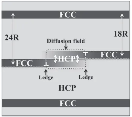
Our results show that, at first, the transformation from 18R- to 24R-type takes place. This transformation takes place locally and accompanies the solution, migration, and re-enrichment of solute elements in the transition region. Here, the strain distribution in the transition region will be considered. The strain maps in Fig. 7 show that, in the transition region, the enrichment layers are separated. The strain in each layer decreased gradually along with decreas-ing Z2-contrast, i.e., the concentration of the solute elements. Based on these results, the schematic model around the transition layer can be proposed as shown in Fig. 9. Figure 6 shows that the stacking sequences are HCP- and FCC-type, respectively, in and outside of the transition region. Then, Shockley partial dislocations exist in ledges between those stacking sequences. The HCP-type transition regions in front of two ledges fuse together and form a kind of diffusionfield, in which the solute elements migrate easily in diffusion
field without changing the stacking sequence in the out-of plane direction of LPSO; the diffusion field in front of the ledge serves as a buffer for the short-range migration of solute elements. Subsequently, the transition region moves in a [0110]Mg or [0110]Mg direction on (0001)Mg planes
accompanying the movement of a pair of partial dislocations. Consequently, the enrichment layer grows or shrinks in the [0110]Mg or [0110]Mg direction. The strain analysis of the
atomic-resolution HAADF-STEM images first clarifies that the diffusionaldisplacive transformation mechanism of the LPSO is limited to within the nano-size transition region, as portrayed in Fig. 7.
The 24R-type LPSO has the same type of stacking of the FCC-type unit as the 18R-type, i.e., they have the same share direction. Then, the transformation does not have large shear strain. Here, a pair of the 18R- and 24R-type spacing (1.56
[image:6.595.318.537.70.265.2]and 2.08 nm, respectively) are identical to double spacing of 14H-type (1.82 nm). Then, the transformation from a pair of the 18R- and 24R-type into double 14H-type fringes produces no normal strain in the [0001]Mg direction.
Figures 13 show that the 24R-type fringe disappears after 30 h-aging. This result agrees well with the transformation through the 24R-type fringe: 18R+24R¼14H+14H.11) The 24R-type irregular fringe in 18R-type LPSO band is necessary for transformation from 18R- into 14H-type LPSO inhibiting the large strain, and acts as a trigger for the transformation in the aging process.
5. Conclusions
Results show the structural and compositional irregularity of LPSO in Mg97Zn1Y2 alloys in atomic resolution using
TEM, HAADF-STEM, and local strain analysis of the images. (1) As-cast alloys have 18R-type LPSO. However, the irregular stacking order is a part of 24R-type LPSO. With aging treatment, the 24R-type irregular fringe and 18R-type LPSO transform to 14H-type LPSO. Finally, the 18R-type LPSO almost completely transforms to the 14H-type LPSO. 24R-type irregular fringes act as a trigger for the transformation.
(2) The transformation from 18R- to 24R-type fringe is conducted by a kind of diffusionaldisplacive trans-formation including structural modulation from FCC- to HCP-type and HCP- to FCC-type, with compositional modulation including the re-solution, migration, and re-enrichment of the solute elements Y and Zn in the enrichment layer.
(3) The front of the transformed region is a ledge-like shape. A Shockley partial dislocation with b=1/3[0110] or b=1/3[0110] is located in front of a ledge. A pair of ledges on the different (0001)Mg planes produces a
transition region, where a kind of diffusion field is localized between the ledges and where the stacking sequence is HCP-type, similar to that of the non-enrichment layer or ¡-Mg matrix. The solute elements migrate in the [0001]Mgdirection in the transition layer
with no structural change. Then, the ledges grow and shrink in the [0110] or [0110] direction.
Acknowledgements
This work was supported by a Grant-in-Aid for Scientific Research on Innovative Areas “Synchronized Long-Period Stacking Ordered Structure®The Evolution of the Material Science for Innovative Development of the Next-generation Lightweight Structure Materials®” (23109006) from the Ministry of Education, Culture, Sports, Science and Tech-nology (MEXT), Japan. The ingots were supported by Kawamura laboratory, Kumamoto University. The electro-discharge machining of the ingots was supported by Mr. Manabu Itoh, Institute for Materials Research, Tohoku University. The usage of electron microscopy was supported by Mr. Shun Itoh, Institute for Materials Research, Tohoku University, and Dr. Kosei Kobayashi, School of Engineering, Tohoku University.
REFERENCES
1) Y. Kawamura, K. Hayashi, A. Inoue and T. Masumoto:Mater. Trans.
42(2001) 11721176.
2) A. Inoue, Y. Kawamura, M. Matsushita, K. Hayashi and J. Koike:
J. Mater. Res.16(2001) 18941900.
3) E. Abe, Y. Kawamura, K. Hayashi and A. Inoue:Acta Mater.50(2002) 38453857.
4) T. Itoi, T. Seimiya, Y. Kawamura and M. Hirohashi:Scr. Mater.51
(2004) 107111.
5) M. Matsuda, S. Ii, Y. Kawamura, Y. Ikuhara and M. Nishida:Mater. Sci. Eng. A393(2005) 269274.
6) Y. M. Zhu, M. Weyland, A. J. Morton, K. Oh-ishi, K. Hono and J. F. Nie:Scr. Mater.60(2009) 980983.
7) Y. M. Zhu, A. J. Morton and J. F. Nie:Acta Mater.58(2010) 2936 2947.
8) E. Abe, A. Ono, T. Itoi, M. Yamasaki and Y. Kawamura:Philos. Mag. Lett.91(2011) 690696.
9) H. Yokobayashi, K. Kishida, H. Inui, M. Yamasaki and Y. Kawamura:
Acta Mater.59(2011) 72877299.
10) D. Egusa and E. Abe:Acta Mater.60(2012) 166178.
11) Y. M. Zhu, A. J. Morton and J. F. Nie:Acta Mater.60(2012) 6562 6572.
12) P. L. Galindo, S. Kret, A. M. Sanchez, J.-Y. Laval, A. Yáňez, J. Pizarro, E. Guerrero, T. Ben and S. I. Molina:Ultramicroscopy 107(2007) 11861193.
13) J. W. Christian:Prog. Mater. Sci.42(1997) 101108.
![Fig. 1(a), (d) Bright field TEM images, (b), (e) selected area diffractionpatterns (SADPs), and (c), (f ) intensity profiles of the SADPs along thec-axis of ¡-Mg matrix ([000l]Mg direction): (a)(c) shows an as-casted and(d)(f ) a 10 h aged alloys](https://thumb-us.123doks.com/thumbv2/123dok_us/319444.530718/2.595.309.547.69.409/bright-selected-diffractionpatterns-intensity-proles-direction-casted-alloys.webp)