known that Fe and its alloys react with Al. Straight Fe-28.2mass%Mn-6.03mass%Si-5.11mass%Cr SMA fibers were arranged on the fiber hold-er, they were immersed into a mold with molten Al. During this step, ferrous SMA reacted with Al at fiber/matrix interface, results in the good bonding strength at interface. After solidification, ferrous SMA fiber/Al matrix composite could be obtained. This composite was subjected to the rolling deformation to induce the martensitic transformation from γ austenite to ε martensite in SMA fibers. Then the composite was heated to induce the reverse transformation from ε martensite to γ austenite. The ferrous SMA fibers in the composite shrank during this reverse trans-formation, which could induce tensile stress in fibers and compressive stress in the matrix. This compressive stress in the matrix is a key factor that enhances the mechanical properties of such smart composite. Mechanical properties of fabricated smart composites were also studied. [doi:10.2320/matertrans.MC201504]
(Received November 4, 2015; Accepted January 22, 2016; Published April 1, 2016)
Keywords: shape memory alloy (SMA), smart material, metal matrix composite (MMC), residual stress, casting, interface
1. Introduction
Owing to the mismatch of the thermal expansion coeffi-cient (CTE) between the matrix and filler, residual stresses are induced in a metal matrix composite (MMC), when the composite is cooled down to room temperature (RT) from the fabrication or annealing temperature1–4). It is strongly
influ-enced by the temperature difference (ΔT) between the fabri-cation temperature and RT, and volume fraction of fillers3).
The combined effects of thermal residual stresses and fiber spatial distribution on the deformation of an Al alloy contain-ing unidirectional boron fibers have been analyzed uscontain-ing de-tailed finite element models5).
If the composites are reinforced by the shape memory alloy (SMA) fiber that shrinks in the matrix, one can introduce an artificial compressive residual stress along the direction of the shrinkage3,4,6), and such composite is called as smart
compos-ite. Many studies have been carried out, but most of them are TiNi SMA fiber/resin matrix system7,8) or TiNi SMA fiber/
Al matrix system. As former examples, studies on TiNi SMA fiber reinforced epoxy matrix composite have been report-ed9,10). As latter studies, many methods are proposed to
fabri-cate the Al matrix smart composite with the TiNi SMA fibers, including vacuum sintering method11), hot isostatic pressing
(HIP) method4), vacuum hot press of TiNi SMA fibers with
sheet shaped Al matrix12,13). On the other hand, fabrication of
Ti matrix and Mg matrix smart composites are also reported. Ti-Pd-Ni-W SMA fiber/Ti matrix smart composite was pro-duced by sheath-rolling14), and TiNi SMA fiber/Mg alloy
matrix smart composite was produced by pulsed current hot pressing15). However, almost all studies are carried out using
expensive TiNi SMA.
Meanwhile, Fe-Mn-Si alloys are inexpensive SMA with the temperature hysteresis as large as 500 K, governed by the fcc (γ) ↔ hcp (ε) transformation16,17). In our previous study18),
an SMA fiber/plaster smart composite, using Fe-27.2mass%Mn-5.7mass%Si-5mass%Cr alloy, and reported that the bending strength of the composite was improved by the compressive stress due to the shape recovery force of the SMA fibers. Although the bonding strength at the SMA fiber/ matrix interface is an important factor, which controls the overall mechanical performance of smart composite struc-tures, the imperfect bonding at interface between SMA fiber and plaster matrix decreases the bending strength of fabricat-ed composite. To overcome this shortcoming, wavy-shapfabricat-ed fiber19–21), coil-shaped fiber22) dumbbell-like shaped bar23)
were used. Twisted NiTi SMA wires/epoxy matrix compos-ites were also developed by Lau et al.24) to improve the
bond-ing properties.
Alternatively in this study, reaction between ferrous SMA fiber and matrix will be used by using Al matrix to increase the bonding properties, since it is well known that solid Fe reacts with molten Al, and this reaction forms intermetallic compound layer25). It is expected that the higher bonding
strength at the interface could be achieved by the reaction be-tween Al matrix and Fe-Mn-Si-Cr SMA fiber.
2. Experimental Procedure
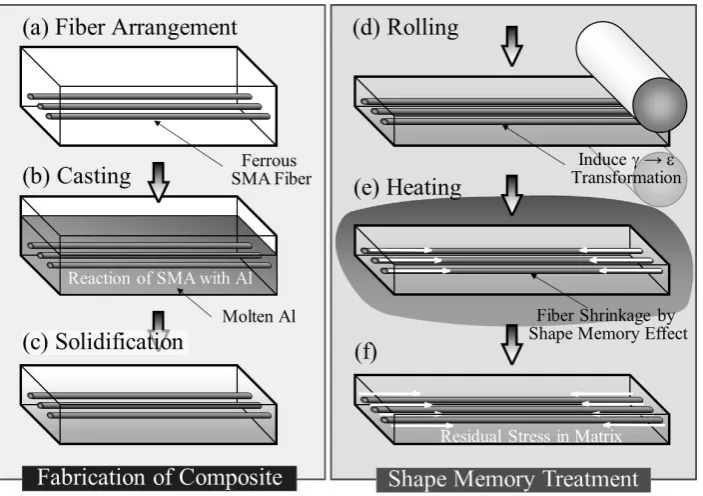
Figure 1 shows the design concept of ferrous SMA fiber/ Al matrix smart composite. Al matrix composite containing ferrous SMA fibers is, first, fabricated by casting route, as shown in Figs. 1 (a) to (c). Straight ferrous SMA fibers are arranged on the fiber holder, as shown in Fig. 1 (a). The mol-ten Al is poured into the mold with the ferrous SMA fibers, as shown in Fig. 1 (b). During this step, ferrous SMA reacts with Al at fiber/matrix interface, result in the good bonding *1
Corresponding author, E-mail: [email protected] *2
strength at interface. After solidification, ferrous SMA fiber/ Al matrix composite can be obtained, as shown in Fig. 1 (c). Immersion of the fiber holder into a mold with the molten Al is alternative method to obtain such composite. Next stage is shape memory treatment to fabricate a smart composite, as shown in Figs. 1 (d) to (f). This composite is subjected to the rolling deformation to induce the martensitic transformation from γ austenite to ε martensite in SMA fibers, as shown in Fig. 1 (d). Then the composite is heated to induce the reverse transformation from ε martensite to γ austenite, as shown in Fig. 1 (e). The ferrous SMA fibers in the composite shrink during this reverse transformation, which induces tensile stress in fibers and compressive stress in the matrix, as shown in Fig. 1 (f). This compressive stress in the matrix is a key factor that enhances the mechanical properties of a smart composite. The internal stress analysis is the critical step for precise evaluation of the smart composite.
In this study, Fe-28.2mass%Mn-6.03mass%Si-5.11mass%Cr SMA fibers of 1 mm diameter were used. In order to study the shape memory effect of the used Fe-Mn-Si-Cr SMA fiber, the relationship between shape recovery versus annealing temperature curves were obtained. Tensile tests were carried out on a screw-driven test machine. The Fe-Mn-Si-Cr SMA fibers with 80 mm in length and 50 mm in gage length are subjected to tensile strains of 5.1, 5.8, 7.2 and 10.3% at RT. Following the tensile deformation, each speci-men was annealed at temperatures ranging from 373 K to 823 K for 600 s for every interval 50 K.
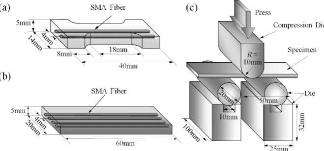
Schematic illustration of fabrication way of composites containing pure Fe fibers or Fe-Mn-Si-Cr SMA fibers and Al matrix is shown in Fig. 2. Straight pure Fe fibers or Fe-28.2mass%Mn-6.03mass%Si-5.11mass%Cr SMA fibers with 1 mm diameter are arranged on the fiber holder, as shown in Fig. 2 (a). When the Al in the mold reached the re-quired temperature (1023 K) (Fig. 2 (b)), the fiber holder with fibers is immersed into the mold with molten Al, as shown in
Fig. 2 (c). After the holding period at 1023 K, the mold was air cooled (Fig. 2 (d)) or furnace cooled (Fig. 2 (d )). Com-posites were also fabricated using with preheated fibers, here preheating of fibers were carried out by putting the fiber hold-er above the mold, as shown in Fig. 2 (b ). Preheating tem-perature is 1023 K. In this study, five types of composites were fabricated, i.e., (1); air cooled composites containing un-preheated Fe fibers, (2); air cooled composites containing un-preheated SMA fibers, (3); air cooled composites contain-ing preheated SMA fibers, (4); furnace cooled composites containing un-preheated SMA fibers and (5); shape memory treated composites using furnace cooled composites contain-ing un-preheated SMA fibers. Hereafter, these composites are abbreviated to (1); Fe composite, (2); un-preheated fiber com-posite, (3); preheated fiber comcom-posite, (4); furnace-cooled composite, and (5); smart composite, respectively.
Bonding strength between the fiber and matrix must be strong enough to provide load transfer, which is directly de-pendent on interfacial growth characteristics of the materials in the system26). Therefore, microstructures at the interfaces
between SMA fiber/Al matrix were carefully studied. Fabri-cated composite samples were cut along the longitudinal di-rection of the fiber, and microstructures of the samples were observed using a scanning electron microscope (SEM) on the longitudinal section of the fiber prepared by conventional grinding and polishing techniques. Energy dispersive X-ray spectroscopy (EDS) analysis was performed to investigate chemical composition at fiber/matrix interface. For evaluat-ing mechanical properties, micro Vickers-hardness (HV) in-dentation tests were carried out at RT. The load and the load-ing time were 98.07 mN and 15 s, respectively.
To obtain smart composites, the furnace-cooled compos-ites are rolled at RT to induce the martensitic transformation from γ austenite to ε martensite in SMA fibers. Rolling re-duction ratio (R) was 20% or 40%. The rolling rere-duction ratio can be written as
[image:2.595.124.476.69.317.2]R=ti−tr
ti ×100(%) (1) where ti and tr are the thicknesses of the samples before and
after cold rolling, respectively. Rolling reduction ratios of composites of 20% and 40% correspond to elongation of fi-bers of 25% and 67%, respectively. The rolled composites were heated up at 573 K for 1200 s to induce the reverse transformation from ε martensite to γ austenite in SMA fi-bers. The above treatment introduces the compressive stress in the Al matrix due to the shape memory effect of SMA fi-bers. The microstructure and hardness of obtained smart composites were also studied.
The tensile specimens, shown in Fig. 3 (a), and three-point bending test specimens with 60 mm × 20 mm × 5 mm in size, shown in Fig. 3 (b), were cut from the smart composites by using an electric discharge machine wire cutter. Tensile tests were conducted at RT at a crosshead speed of 2.0 mm/min using an Instron-type testing machine. A three-point bending test was performed using the Instron-type testing machine at a crosshead speed of 1 mm/min. Figure 3 (c) shows the
three-point bending test setup, where the lower span length of the bending test specimen was 50 mm. The specimen was loaded until fracture occurred, and bending strength was calculated from the load-stroke curves.
3. Experimental Results and Discussion
3.1 Shape memory effect of Fe-Mn-Si-Cr SMA fiber The Fe-Mn-Si-Cr SMA fibers with 80 mm in length and 50 mm in gage length are subjected to tensile strains of 5.1, 5.8, 7.2 and 10.3% at RT, and annealed at temperatures rang-ing from 373 K to 823 K to measure the shape memory ef-fect. Figure 4 shows the fraction of shape memory recovery values plotted against annealing temperatures for the Fe-Mn-Si-Cr SMA fibers. The fraction of shape memory recovery value is nearly constant above 723 K. Moreover, it is also found that the shape memory effect decreased with increasing pretensile strain, which agrees with the previous results16,17).
3.2 Fe composite
As a preliminary experiment, an air cooled composite con-Fig. 2 Schematic illustration of fabrication way of composites containing Fe fibers or Fe-Mn-Si-Cr SMA fibers and Al matrix. Fabricated composites are (1);
air cooled composites containing un-preheated Fe fibers (Fe composite), (2); air cooled composites containing un-preheated SMA fibers (un-preheated fiber composite), (3); air cooled composites containing preheated SMA fibers (preheated fiber composite), (4); furnace cooled composites containing un-preheat-ed SMA fibers (furnace-coolun-preheat-ed composite), and (5); shape memory treatun-preheat-ed composite using furnace coolun-preheat-ed composites containing un-preheatun-preheat-ed SMA fibers (smart composite).
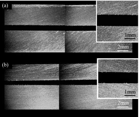
[image:3.595.92.499.67.256.2] [image:3.595.132.462.334.488.2]taining un-preheated Fe fibers (Fe composite) was fabricated, where holding period was 300 s. The cross section of the composite was observed along the Fe fiber, and lower magni-fication photograph and higher magnimagni-fication photograph with EDS analysis results are shown in Figs. 5 (a) and (b), respectively. In both figures, upper and lower regions corre-spond to Al matrix and Fe fiber, respectively. It is seen from these figures that an interlayer, appeared by reaction between
molten Al and Fe fiber, was found at the Al matrix/Fe fiber interface. According to composition analysis by EDS, the Al matrix was alloyed with Fe, and the interlayer was Al2Fe
in-termetallic compound. Maximum thickness of the interlayer was found to be 122 μm. Although some pores were observed at the interface, it is expected that the higher bonding strength at the interface could be achieved by the reaction between Al matrix and Fe fiber.
3.3 Un-preheated fiber composite
An air cooled composite containing un-preheated Fe-Mn-Si-Cr SMA fibers (un-preheated fiber composite) was fabri-cated, where the holding period was 1800 s. Figure 6 shows Fig. 4 Fraction of recovery values for Fe-Mn-Si-Cr SMA fibers as a
func-tion of annealing temperature.
Fig. 5 The cross section views of the Fe composite. (a): lower magnifica-tion photograph, and (b): higher magnificamagnifica-tion photograph with EDS analysis results.
[image:4.595.59.280.66.235.2] [image:4.595.313.543.68.574.2] [image:4.595.55.283.284.630.2]the fiber/matrix interface in the un-preheated fiber compos-ite, where upper and lower regions correspond to Al matrix and SMA fiber, respectively. From EDS analysis as shown in Fig. 6 (b), reaction between Al matrix and SMA fiber could be recognized. There are two interlayers, those are Al rich interlayer appeared at Al matrix side and Fe-Mn-Si-Cr based interlayer found at SMA fiber side. Again, it is expected that the higher bonding strength at the interface could be achieved by the reaction between Al matrix and SMA fiber. However, pores were also observed at the interface, as shown in Fig. 6 (a).
Macrophotograph observed along the longitudinal section of the composite is shown in Fig. 7. In this figure, center part is SMA fiber. It must be noted that some gaps and cavities could be observed between SMA fiber and Al matrix. This is because the thermal expansion coefficient of pure Al at 300 K, 600 K and 800 K is reported to be 23.2 × 10⁻⁶ 1/K, 28.4 ×
10−6 1/K and 34.0 × 10⁻⁶ 1/K, respectively27). On the other
hand, the thermal expansion coefficient of Fe-Mn-Si SMA is 16.5 × 10⁻⁶ 1/K between 273 K and 773 K28), which is
small-er than that of pure Al. In ordsmall-er to eliminate such gaps and cavities, the composites should be fabricated under slower cooling rate. In the next session, the results of preheated fiber composite will be described.
3.4 Preheated fiber composite
Figure 8 shows macrophotograph observed along the lon-gitudinal section of the preheated fiber composite. In this case, the preheated SMA fibers were immersed into the mol-ten Al in the mold, and after the holding period at 1023 K, mold was air cooled. It is seen that the gaps and cavities were not observable between SMA fiber and Al matrix.
Figures 9 (a), (b) and (c) show higher magnification photo-graphs at the fiber/matrix interface regions of the air cooled composite containing SMA fibers with preheating, where holding period is 0 s, 600 s and 1500 s, respectively. Upper and darker contrast region is Al matrix and lower and lighter contrast region is SMA fiber. It is seen from these figures that clear interfaces between Al matrix and SMA fibers were ob-served. Moreover, the influence of holding period on inter-face structure was not observed.
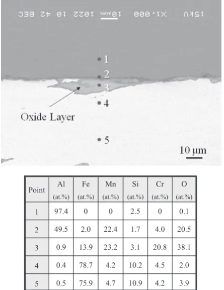
Figure 10 shows the results of compositional analysis near the fiber/matrix interface in preheated fiber composite by EDX. It is seen that oxide phases were clearly observed
be-tween SMA fiber and Al matrix, and the surface of SMA fi-bers was covered by oxide-layer. This is because the SMA fibers were preheated under an air atmosphere. This oxide layer inhibited the reaction between SMA fiber and Al ma-trix. Therefore, preheating of SMA fibers is not the best way to fabricate the composite including fiber/matrix interface with good bonding strength. Otherwise, furnace cooled com-posites containing un-preheated SMA fibers (furnace cooled composites) were fabricated to achieve the slower cooling rate.
3.5 Furnace-cooled composite
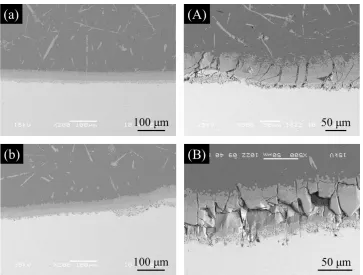
SEM microstructures of the fibers in the furnace cooled composites taken at the center region of the samples are shown in Figs. 11 (a) and (b), where holding period was 0 s and 300 s, respectively. In these cases, the un-preheated fibers were immersed into the molten Al in the mold, and after the holding period at 1023 K, and then the mold was furnace cooled. It is seen from these figures that clear interlayer was observed between Al matrix and SMA fibers.
Figures 12 (a) and (b) show magnified SEM micrographs showing the fiber/matrix interface in the furnace cooled com-Fig. 7 Macrophotograph observed along the longitudinal section of the un-preheated fiber composite.
[image:5.595.117.479.68.219.2] [image:5.595.307.548.261.464.2]posites fabricated by holding period of 0 s and 300 s, respec-tively. EDS analysis results for furnace cooled composites fabricated under holding period of 0 s and 300 s are shown in Figs. 13 (a) and (b), respectively. In these figures, upper and lower regions correspond to Al matrix and SMA fiber, respec-tively. It is seen from these figures that significant reaction between SMA fiber and molten Al occurred, and interlayer could be observed between SMA fiber and Al matrix. More-over, thickness of the interlayer in the composite fabricated by holding period of 300 s is larger than that by holding peri-od of 0 s. The bonding strength between SMA fiber and Al matrix in the furnace cooled composites must be strong enough to provide load transfer. The furnace cooled compos-Fig. 9 Typical interfacial microstructures formed in the preheated fiber
[image:6.595.64.274.68.568.2]composites. Upper and lower regions are Al matrix and SMA fiber, re-spectively. Holding period at 1023 K is (a); 0 s, (b); 600 s and (c) 1500 s.
[image:6.595.316.539.71.360.2]Fig. 10 Magnified SEM micrograph with EDS analysis results of inter face structure in preheated fiber composite. Holding period is 0 s.
[image:6.595.322.532.418.745.2]ites were, therefore, used as initial materials to fabricate the smart composites.
Figures 12 (A) and (B) show the fiber/matrix interfaces in
[image:7.595.117.481.67.342.2]the furnace cooled composites after rolling reduction ratio of 20%. As can be seen, fracture of the interlayer consists with brittle intermetallic compounds could be observed. In the Fig. 12 Magnified SEM micrograph showing the fiber/matrix interface in the furnace cooled composites, (a) and (b); before rolling and (A) and (B); after
[image:7.595.100.499.403.703.2]rolling of R = 20%. Upper and lower regions correspond to Al matrix and SMA fiber, respectively. Holding period is 0 s for (a) and (A) and 300 s and for (b) and (B).
case of sample fabricated under holding period of 0 s with thinner interlayer, most of the cracks were parallel to the radi-al direction as shown in Fig. 12 (A), while cracks parradi-allel to the longitudinal direction of fiber were also observed in the sample fabricated under holding period of 300 s with thicker interlayer as shown in Fig. 12 (B). The cracks paralleled to the longitudinal direction may reduce the bonding strength at the interface; however, those paralleled to the longitudinal di-rection of fiber may not have strong influence on reducing the bonding strength.
3.6 Smart composite
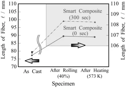
Length of SMA fibers in furnace cooled composites fabri-cated under holding period of 0 s and 300 s is shown in Fig. 14. As can be seen from Fig. 14, elongation of SMA fi-bers was observed by rolling with rolling reduction ratio of 40%. It must be noted that remarkable shrinkage of SMA fi-ber in the smart composites by heating at 573 K was found, which induces compressive stress in the Al matrix.
3.7 Hardness test
Figure 15 shows the micro-hardness within the fur-nace-cooled composite, furfur-nace-cooled composite after 20% rolling and smart composite (shape memory treatment at
573 K after 20% rolling), where holding period of these com-posites is 0 s. Micro-hardness values of as cast pure Al, pure Al after rolling and pure Al after rolling and heating are also shown in this figure. As seen from Fig. 15, the hardness of pure Al sample was increased by the rolling due to work hard-ening, but decreased by heat treatment after the rolling due to recrystallization. The hardness of SMA fiber region was also increased by the rolling due to γ to ε martensitic transforma-tion and work hardening, but decreased by heat treatment due to ε to γ reverse transformation. It must be noted that the composites had very high hardness at the interface region of the SMA fiber with intermetallic compound phases, and rela-tively higher hardness in Al matrix near the interface. In this way, the fabricated composites had a graded hardness profile at interface region. The most remarkable result shown in Fig. 15 is that the shape memory treatment increased the hardness of Al matrix, namely, matrix hardness of the smart composite (shape memory treatment at 573 K after 20% roll-ing) is larger than that of rolled composite, due to compres-sive stress introduced by the shape memory effect of the SMA fibers.
[image:8.595.58.283.70.223.2]To discuss this phenomenon, the micro-hardness value of Al matrix in each composite at 30 μm from interface is shown in Fig. 16. Micro-hardness of as cast pure Al, pure Al after 20% rolling and pure Al after rolling and heating are also shown in this figure. All of the composites had higher hard-ness because of diffusion of some elements from the SMA fiber. Same amount of work hardening was observed for all samples. Although softening was found for Fe fiber compos-ite and pure Al sample by heating, hardening could be found for the smart composites because of compressive stress intro-duce by shape memory treatment. It is expected that the smart composites may provide higher mechanical properties, such as proof stress, tensile strength and bending strength, than composites without shape memory treatment. Moreover, hardening effect by heating for the smart composite fabricat-ed by holding period of 0 s is larger than that by holding peri-od of 300 s. This maybe come from the directions of the cracks observed at the interlayer, i.e., cracks paralleled and Fig. 14 Shape memory effect of Fe-Mn-Si-Cr SMA fibers in furnace cooled
composites fabricated under holding period of 0 s and 300 s.
[image:8.595.314.536.72.256.2]Fig. 15 Micro-hardness within the air-cooled composite, air-cooled com-posite after 20% rolling and smart comcom-posite (shape memory treatment at 573 K after 20% rolling). These composites were fabricated by holding period of 0 s. Micro-hardness values of as cast pure Al, pure Al after roll-ing and pure Al after rollroll-ing and then heatroll-ing are also shown in this figure.
[image:8.595.52.286.271.422.2]perpendicular to the longitudinal direction do and do not re-duce the bonding strength, respectively.
3.8 Tensile test
Tensile tests were conducted at RT and some examples of nominal stress - nominal strain curves for the smart compos-ites and Fe composcompos-ites, cast under holding period of 300 s, are shown in Fig. 17. These composites were rolled with roll-ing reduction ratio of R = 0% (without rollroll-ing), 20% or 40% and then heat treated at 573 K. It is seen that the flow stress of the composites increased with increasing the rolling reduc-tion ratio in both smart and Fe composites.
0.2% proof stress and tensile strength of each sample are evaluated from the nominal stress - nominal strain curves and results are plotted against the rolling reduction ratio, as shown in Figs. 18 (a) and (b), respectively. It is seen from this figure, 0.2% proof stress and tensile strength of the smart composites were enhanced by the rolling. However, since those of Fe composite and pure Al sample were also increased by in-creasing the rolling reduction ratio, higher 0.2% proof stress and tensile strength in the smart composites with higher roll-ing reduction ratio were not the reason of shape memory ef-fect by SMA fibers. It is known that 0.2% proof stress of pure Al (1100-O) is 35 MPa29). Therefore, decreasing the casting
defects by the rolling may increase the 0.2% proof stress and tensile strength.
3.9 Bending test
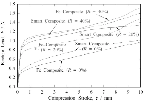
Three-point bending test was performed and some exam-ples of bending load versus compression stroke curves for the smart composites and Fe composite are shown in Fig. 19, where these composites were cast under holding period of 300 s, and rolling (R = 0%, 20% or 40%) and heat treatment at 573 K were carried out. It is seen from this figure, the bend-ing load increased with increasbend-ing compression stroke at least up to 10 mm. It is worthwhile to notice that the bending load of the composites increased with increasing the rolling ratio.
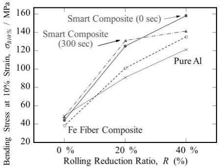
[image:9.595.46.289.61.270.2]Bending flow stress at 10% strain of each sample is evalu-ated from the bending load versus compression stroke curves. The results are plotted against the rolling reduction ratio, and are shown in Fig. 20. As can be seen, all of the samples before the rolling shows the similar bending flow stress values. The higher bending flow stress was found for the samples rolled with larger rolling reduction ratio, which is similar to the re-sults of tensile test. It must be noted here that enhanced bend-ing flow stress was found for the smart composites, despite the fact that remarkable effect of compressive stress introduce by shape memory effect was not found in tensile and bending Fig. 17 Examples of nominal stress - nominal strain curves for the smart
[image:9.595.319.534.68.373.2]composites (holding period of 300 s) and Fe composites with rolling re-duction ratio of R = 0%, 20% or 40%. Rolled samples were heat treated at 573 K.
Fig. 18 0.2% proof stress and tensile strength of each sample plotted against the rolling reduction ratio.
[image:9.595.306.546.414.584.2]properties.
Mechanical property at local region can be evaluated by the micro hardness test, while overall mechanical properties can be evaluated by the tensile test. Therefore, enhancement of mechanical property of smart composites induced by shape memory effect may limit at the interface region of SMA fiber and Al matrix.
4. Conclusions
In this study, Al matrix smart composites containing Fe-28.2mass%Mn-6.03mass%Si-5.11mass%Cr straight SMA fibers are studied. As preliminary experiments, four types of composites are fabricated by casting, i.e., air cooled compos-ites containing un-preheated Fe fibers, air cooled composcompos-ites containing un-preheated SMA fibers, air cooled composites containing preheated SMA fibers, and furnace cooled com-posites containing un-preheated SMA fibers. To fabricate smart composite, the furnace cooled composites containing un-preheated SMA fibers is subjected to the rolling deforma-tion to induce the martensitic transformadeforma-tion in SMA fibers and heating to induce the reverse transformation. The ferrous SMA fibers in the composite shrink during this reverse trans-formation, which induces tensile stress in fibers and compres-sive stress in the matrix. The matrix hardness of the smart composite is larger than that of rolled composite, due to com-pressive stress introduced by the shape memory effect of the SMA fibers. However, remarkable effects of compressive stress introduce by shape memory effect on proof stress and tensile strength are not observed. Enhancement of mechani-cal property of smart composites induced by shape memory effect may limit at the interface region of SMA fiber and Al matrix.
(1997) 313–317.
5) T. Nakamura and S. Suresh: Acta Metall. Mater. 41 (1993) 1665–1681. 6) Y. Furuya, A. Sasaki and M. Taya: Mater. Trans., JIM 34 (1993) 224–
227.
7) J. Schrooten, V. Michaud, J. Parthenios, G.C. Psarras, C. Galiotis, R. Gotthardt, J.-A. Månson and J.V. Humbeeck: Mater. Trans. 43 (2002) 961–973.
8) K. Yamashita and A. Shimamoto: Trans. Jpn Soc. Mech. Eng. Ser. A 74 (2008) 1544–1549 (in Japanese).
9) A. Shimamoto and M. Taya: Trans. Jpn Soc. Mech. Eng. Ser. A 63 (1997) 26–31 (in Japanese).
10) G. Murasawa and S. Yoneyama: Mater. Trans. 47 (2006) 766–771. 11) Y. Furuya and M. Taya: J. Japan Inst. Metals 60 (1996) 1163–1172 (in
Japanese).
12) K. Hamada, J.H. Lee, K. Mizuuchi, M. Taya and K. Inoue: Metall. Ma-ter. Trans., A Phys. Metall. MaMa-ter. Sci. 29 (1998) 1127–1135. 13) W.D. Armstrong, T. Lorentzen, P. Brøndsted and P.H. Larsen: Acta
Ma-ter. 46 (1998) 3455–3466.
14) K. Mizuuchi, K. Yamauchi, K. Hamada, K. Inoue, M. Taya and K. Ena-mi: J. Japan Inst. Metals 61 (1997) 727–735 (in Japanese).
15) K. Mizuuchi, K. Inoue, K. Hamada, M. Sugioka, M. Itami, M. Fukusu-mi and M. Kawahara: Mater. Sci. Eng. A 367 (2004) 343–349. 16) A. Sato, E. Chishima, K. Soma and T. Mori: Acta Metall. 30 (1982)
1177–1183.
17) Y. Watanabe, Y. Mori and A. Sato: J. Mater. Sci. 28 (1993) 15091514. 18) Y. Watanabe, E. Miyazaki and H. Okada: Mater. Trans. 43 (2002) 974–
983.
19) Y. Watanabe, E. Miyazaki and H. Okada: Trans. Mater. Res. Soc. Jpn. 28 (2003) 671–674.
20) T. Wakatsuki, Y. Watanabe and H. Okada: Mater. Sci. Forum 475–479 (2005) 2063–2066.
21) S. Tanaka, H. Okada, Y. Watanabe and T. Wakatsuki: Inter. J. Multiscale Comput. Eng. 4 (2006) 411–428.
22) T. Wakatsuki, H. Sato, Y. Watanabe and T. Maruyama: Tetsu-to-Hagane 92 (2006) 562–566 (in Japanese).
23) T. Sawaguchi, T. Kikuchi, K. Ogawa, S. Kajiwara, Y. Ikeo, M. Kojima and T. Ogawa: Mater. Trans. 47 (2006) 580–583.
24) K.-t. Lau, W.-y. Tam, X.-l. Meng and L.-m. Zhou: Mater. Lett. 57 (2002) 364–368.
25) K. Bouché, F. Barbier and A. Coulet: Mater. Sci. Eng. A 249 (1998) 167–175.
26) J.P. Coughlin, J.J. Williams, G.A. Crawford and N. Chawla: Metall. Mater. Trans., A Phys. Metall. Mater. Sci. 40 (2009) 176–184. 27) Japan Society of Thermophysical Properties ed.: Thermophysical
Prop-erties Handbook (Yokendo, Tokyo, 1990), p. 22, (in Japanese). 28) T. Maruyama and T. Kurita: Kinzoku (Mater. Sci. Tech.) 74 (2004)
160–163 (in Japanese).
[image:10.595.56.280.69.239.2]29) I. J. Polmear: Light Alloys, Metallurgy of the Light Metals, Third Edi-tion (Halsted Press, New York, 1996), p. 91.