Molecular Dynamics Simulation on Interaction between Screw Dislocation
and Pseudo Yttrium Oxide in Bcc-Fe
K. Yashiro
1, A. Yamaguchi
2,+, M. Tanaka
2,+, T. Okuda
3, K. Koga
3and T. Segi
31Graduate School of Kobe University, Kobe 657-8501, Japan
2Student of Graduate School of Kobe University, Kobe 657-8501, Japan 3Kobelco Research Institute, Inc., Kobe 651-2271, Japan
For an atomistic insight in oxide dispersion strengthened (ODS) steels, we have performed molecular dynamics simulations on interaction between screw dislocation and nanoparticle of“pseudo”oxide, by using simple Johnson potential. Various dislocationobstacle interactions are investigated for 2 nm oxides of coherent bcc, incoherent hcp and“hollow”without oxide, on each slip planes off110gandf112g, respectively. Although it is not a feature of oxide, we have found“Saturn ring”defects around the incoherent oxide and hollow on thef112gslip plane, and revealed the mechanism; that is, screw dislocation should leave vacancies to shorten or elongate its length between the incoherent interfaces or surface of hollows. Screw dislocation on thef110gslip plane doesn’t form such ring due to the cross-slip; however, it forms“entanglement” around the incoherent oxide. On the other hand, the screw dislocation never“splits”against the coherent precipitates so that it leaves little defect around the coherent oxide. [doi:10.2320/matertrans.M2011276]
(Received September 5, 2011; Accepted November 18, 2011; Published January 25, 2012)
Keywords: oxide dispersion strengthened (ODS) steel, molecular dynamics simulation, screw dislocation, yttrium oxide, saturn ring vacancies, dislocation entanglement, ab-initio density functional theory (DFT) calculation
1. Introduction
Oxide dispersion strengthened (ODS) steels are potential next-gen materials for fuel cladding tubes at nuclear power plants. For the engineering application and further develop-ments of desired steels, it is urgent to understand the key mechaism of their superior properties against neutron irradiation and high temperature. Starting from the pioneering report for alloying elements and mechanical alloying process of ODS steels in 1989,1)experimental studies have revealed
the relationship between internal microstructure and mechan-ical properties,2)improvement of tensile and creep properties by extremely fine YTiO clusters with Ti addition,3) quantitative evaluation of nanosized oxides,4) and so on. The fine oxides, of a few nanometer size, are expected to prevent the free dislocation motion so far; however, due to the complexity of mechanical alloying and recrystalization process, it is still difficult to show the direct evidence even with the recent advancement of experimental technique such as TEMin situtest.
Computational approach would be one answer to tackle these difficulties. In thefield of physics of crystal plasticity, various dislocation-obstacle problems have long been discussed using molecular dynamics (MD) and discrete dislocation dynamics (DDD) simulations;5,6) and we have
also discussed the dislocation motion in£=£0 microstructure in Ni-based superalloys.7,8) However, there is no suitable potential function which can represent all the bonding state, i.e. metal, ion and covalent systems with sufficient number of atoms needed for deformation simulation. Of course the ab-initio density functional theory (DFT) calculation can treat mixing of any atom species, however, the calculation is so far limited to very small system at most a few hundred atoms. Thus quite a few atomistic simulations can be found for ODS steels except for lattice Monte Carlo (LMC) simulation, in
which atom position is restricted on regular lattice site, so that the limited combination of local bonding can be precisely determined by ab-initio DFT calculation. Alinger et al.9) performed the LMC simulation of FeYTiO system and discussed the structure and morphology of precipitated nanocluster. Hin et al.10) simulated more realistic
precipita-tion by kinetic LMC, considering the different diffusion mechanism (O atoms by interstitial jumps and Fe and Y atoms by vacancy jumps). Both studies apply finer lattice mesh than the usual bcc lattices and their results should be appreciated as accurate prediction based on DFT data. However, we would confront to drastic increase in the combination of local bonding if we applied these DFT-LMC analysis to many alloy elements system for real ODS steel design. Moreover, we never apply these DFT-LMC scheme to disordered structure, such as dislocations and grain boundaries, since we should consider enormous mesh much more than the number of atoms involved.
From an engineering point of view, we need an atomistic simulator in which the potential functions have differentiable form for dynamic simulation and they are also easy tofit for new elements interest. The 2-body potential form is the simplest way and there are many resourcesfitted for various elements; however, obviously we would fail to represent the bonding between oxygen and metallic atoms if wefitted them separately in the 2-body form. Thus, in the present study, we don’t distinguish the Y and O atoms in Y2O3crystal but treat
as “monatomic” pseudo-atom of YO, and the potential parameters arefitted to the DFT results of explicit Y and O aoms in hcp lattice. By virtue of this rough approximation, we can easily implement atomistic simulation using conven-tional resources, e.g. Johnson potential parameters for Fe,11) keeping the rough characteristics of oxides such as lattice parameters and bulk modulus. Although we cannot validate the physical meaning of the isolated pseudo-atom nor discuss the formation and structure of new oxidation products, we can perform various molecular dynamics simulations of +Graduate Student, Kobe University
interest. In the present study, we show the brieffitting process and perform molecular dynamics simulations on the interaction between screw dislocation and nano-sized oxide of coherent bcc, incoherent hcp and hollow without oxide in bcc-Fe matrix, for each slip planes of f110g and f112g, respectively.
2. Simulation Procedure
2.1 Potentialfitting
DFT calculations for potential fitting are implemented using the Vienna Ab-initio Simulation Package (VASP) developed by Kresse and Hafner.12) Although the Y
2O3,
M2X3 type metal oxide, is reported to form the C-rare earth
oxide structure,13)it is very difficult to directly consider such
a low-symmetric irregular structure by DFT calculation. Thus we have roughly approximated the structure of Y2O3 by
simple hcp lattice, which is close to the corundum structure or the second candidate of M2X3metal oxide. Figure 1 shows
the rhombohedral unit cells for hcp lattice. The supercell for DFT calculation has one Y-atom and one O-atom at the lattice point as shown in Fig. 1(a). Keeping the atom position at the lattice point, or statically, we have changed the lattice parameter a and performed DFT calculation to obtain the energylattice parameter curve. The ultrasoft pseudopoten-tial14)is adopted and the exchange correlation term is treated in the formulation of GGA (generalized gradient approx-imation).15) The cutoff energy and number of k points are
296.9 eV and 15©15©15, respectively.
Johnson potential expresses the system energy,Etot, by the
following form:11)
Etot¼
X
i
X
j>i
½C1ðrijC2Þ3þC3rijC4 ð1Þ
hererijis the distance between atomsiandj, and the potential
parameterC1C4should be found for yttrium oxide. We have
expressed the infinite hcp crystal with monatomic YO pseudo-atoms in Fig. 1(b) under the periodic boundary, and
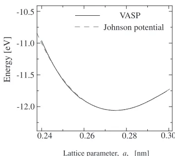
fitted its energy change to the DFT result (Fig. 2). By this
fitting process, the equilibrium lattice length and the bulk modulus, or energy change rate against lattice expansion/ compression, are precisely represented for monatomic YO pseudo-atoms. On the FeYO interaction, simple arithmetic average rule is adopted, i.e.,ðCFei þCYOi Þ=2. All the potential parameters are listed in Table 1.
2.2 Simulation models
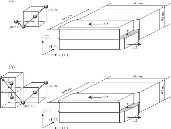
Two screw dislocations with opposite Burgers vectors are introduced in bcc Fe as schematically shown in Fig. 3. Each cell has 840 000 and 835 200 atoms, respectively. In the initial configuration, we applied gradual displacement between slipped and non-slipped region as schematically illustrated in the figure, and its width is four unit lattices in each crystal orientation. The initial structure is relaxed by 10 000 fs molecular dynamics simulation under the periodic boundary conditions in thexandyaxes, i.e., dislocation line and glide directions, and fixed boundary in thezaxis at the top and bottom with each 3 atom layer. The temperature is controlled very low at T=0.1 K by velocity scalling, since we want to eliminate the thermal effect at the present basic simulations. The cell size is also adjusted to cancel the normal stress during the relaxation.
Then we have set two obstacles in the simulation cell as shown in Fig. 4, which indicates the outer radius of the obstacles,R, distance to the dislocation,d, and the margin of the interface for incoherent precipitates,¤. We add the marks of and to indicate the screw character or the lattice discrepancy direction. Both the distance d and radius R are set to 2 nm in the present paper. We can simply substitute Fe atoms with YO pseudo-atom in the radius R for coherent precipitation; however, we have wide variety for incoherent precipitation, e.g. the crystal axis of the precipitate and width of interface. For the simplicity, the hcp YO ball is oriented in the [1000], [0110] and [0001] for the x, y and z axes, respectively, and the width of interface or margin ¤is set to 0.2 nm. Here the margin of 0.2 nm is the overlapping limit of FeFe bonding of Johnson potential. We also considered the hollow of radius R=2 nm. The simulation models are summarized in Table 2.
60o 60o 60o
60o Y
O
1.66
a
a
a (a)
60o 60o 60o
60o YO
YO (b)
Fig. 1 Rhombohedral unit cells for hcp structure. (a) hcp unit cell for DFT calculation (b) hcp unit cell for monatomic“YO”.
VASP Johnson potential
Ener
gy [eV]
0.24 0.26 0.28 0.30
-12.0 -11.5 -11.0 -10.5
Lattice parameter, a, [nm]
[image:2.595.337.514.66.224.2]Fig. 2 Free-energy curves against lattice expansion/compression by DFT calculation for discriminated Y and O in the hcp structure and by Johnson potentialfitted as monatomic YO mean-atom.
Table 1 Potential parameters for Fe and YO pseudo-atom.
Element Range [nm] C1 C2 C3 C4
Fe
[image:2.595.305.548.297.366.2] [image:2.595.54.283.652.759.2]These structures are relaxed during 20 000 fs calculation after setting the obstacles, confirming that the dislocation doesn’t move without external loading. Then the zx shear strain increment of ¦£zx=1.0©10¹6 is applied at every
step, up to the total strain of £zx=0.05 during 50 000 fs.
The shear direction is that of resolving the initial lattice discrepancy, so that the dislocations approach to the obstacles. Here, it should be noted that the dislocation doesn’t move up to the strain of about 0.1, if the simulation
cell doesn’t include these obstacles. After reaching the maximum strain, we stopped the strain increase and held the shear during additional 20 000 fs.
3. Results and Discussion
Figure 5 shows the stressstrain curves of all the simulations. The first yield or the limit of the linearity corresponds to the point when the screw dislocations start to glide. There is no large difference in the stress strain curves in each glide plane, even if we don’t set the oxide in the hollow. All the dislocations passes through the obstacles without remarkable resistance in thef112gslip, while they bypass the obstacles by cross slip in thef110gmodels as shown later.
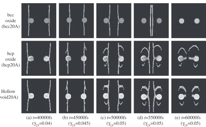
Figure 6 shows the motions of screw dislocations in the simulation of f112g slip plane. The dislocation core and hollow surface are visualized by a simple criteria of
¦E=E¡¹E0>0.02 eV, hereE¡is the potential energy of
atom¡and E0=¹1.48995 eV is that in the equilibrium bcc
lattice atT=0 K. We can also obtain samefigures by central symmetrical parameter of AtomEye,16) except the coherent
YO atoms. The screw dislocations leave no defect and annihilate each other, after cutting through the coherent precipitates in Bcc20A. On the other hand, we canfind that screw dislocation leaves Saturn-ring like defects when it passes through the channel between the periodic array of the oxides [Figs. 6(b) and 6(c)], drags dislocation junction when it escapes from the oxides [Fig. 6(d)] andfinally annihilates leaving the tail-like defects at the center [Fig. 6(e)]. Definitely the ring is not brought by the Orowan loop mechanism. Since the dislocation shows very similar motion against the hollow in Void20A, we can conclude that this is not the effect of the oxide but the incoherent interface/free surface of the hollow. That is, the screw dislocation is split to have its ends on the interface/surface of the obstacles. We confirmed it from both the change in the von Mises shear strain on the glide plane and the actual motion of YO atoms
b/2
b
b/2
x [111]
y [110] _ _
24.8 nm
9.8 nm
40.4 nm
_
Line dir.
glide dir.
b/2
b
b/2
x [111]
y [112] _
_
24.8 nm
9.7 nm
40.6 nm
_
Line dir.
glide dir.
(a)
(b)
Fig. 3 Simulation models for screw dislocation. (a) Simulation cell forf112gslip plane (b) Simulation cell forf110gslip plane.
R d d
x [111]
δ
dislocation
glide direction
y [110] or [112]
_ _ _
y [110] or [112]
_ _ _ z [112]
or [110]
_ _ _
top view
side view
front vie
w
[image:3.595.153.446.76.296.2]Fig. 4 Schematic of obstacle setting and camera angle.
Table 2 List of simulation performed.
Model Name
RadiusR
[nm]
Margin¤ [nm]
Oxide structure
Slip plane
bcc20A 2 0 bcc
f112g
hcp20A 2 0.2 hcp
void20A 2 ® ®
bcc20A_110 2 0 bcc
f110g
hcp20A_110 2 0.2 hcp
[image:3.595.51.291.348.489.2] [image:3.595.48.290.544.645.2]in Bcc20A and Hcp20A; i.e., the incoherent oxide changes its shape not by the passage of screw dislocation but by the migration of surface atoms of the hcp ball, while the coherent oxide is actually cut and shifted at the center glide plane. Careful observation on these defects reveals the following facts; (1) these defects are generated on the glide plane, (2) the Saturn ring has vacancy character while the tail interstitial, (3) these defects are not caused only by the periodicity since the location is not doubled even if we doubled the simulation cell in the x direction. Finally we obtained the conclusion summarized in Figs. 79; the most important point is that the screw dislocation should leave vacancies, if it changes its length in thefinite lattices between the obstacles (Fig. 7). Perhaps this simple fact is not recognized in the dislocation theory, since the dislocation loop can change its form in the infinite body. Even though Fig. 7 shows only the case for dislocation shortening, it is also true for the elongation after passing the narrowest channel. Figure 8 is the explanation for the difference of the small and large ring, or the different characters of dislocation ends at the interface/surfaces. Of course there is no
difference in the “intrusion”and “extrusion”for the hollow surfaces without external loading; however, there would be a slight difference between “push in” and “push out” the lattices under shear. Although we cannot show the clear evidence, it would be supported by the fact that the rings in Void20A are rather symmetrical compare to those in Hcp20A. The last Fig. 9 is for the tail-like interstitials;
Applied shear strain, γzx
Shear stress,
τzx
, GP
a
{110} slip plane
_
bcc20A_110 hcp20A_110 void20A_110
0 0.01 0.02 0.03 0.04 0.05 1
2 3
Applied shear strain, γzx
Shear stress,
τzx
, GP
a
{112} slip plane
_ _
bcc20A hcp20A void20A
0 0.01 0.02 0.03 0.04 0.05 1
2 3
(a) (b)
Fig. 5 Stressstrain curves. (a)f112gslip (b)f110gslip.
(a) t=40000fs (γzx=0.04)
(b) t=45000fs (γzx=0.045)
(c) t=50000fs (γzx=0.05)
(d) t=55000fs (γzx=0.05)
(e) t=60000fs (γzx=0.05) hcp
oxide (hcp20A)
bcc oxide (bcc20A)
Hollow (void20A)
Fig. 6 Snapshots of high-energy Fe and YO atoms (top view,f112gslip plane).
b
b
L=n lattices
b
b d
d n-2d lattices
Length L
Vacancies for 2d needed!
=
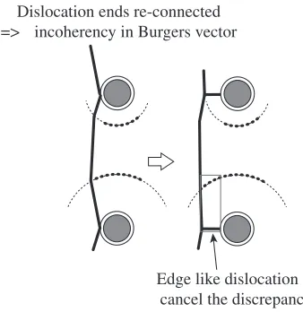
[image:4.595.136.462.73.240.2] [image:4.595.121.478.277.497.2] [image:4.595.310.542.537.657.2]that is, the dislocation would have a lattice discrepancy due to the vacancies of large ring, if the dislocation ends were re-connected and going to glide from the tail of obstacles. Thus the re-connected dislocation drags junction with edge dislocation like interstitials. The longer tail defects in Hcp20A would support this mechanism, since the overshoot of the large ring is quite long compare to that in Void20A. However, this mechanism may contain the periodicity problem so that we don’t insist on the significance so far.
Finally we show Fig. 10 of the dislocations and defects after 20 000 fs holding at£zx=0.05 in thef110gslip, by the
central symmetry parameter of AtomEye. At the yield point in Fig. 5(b), the screw dislocations begin to glide not on the center f110g slip plane but in the tilt directions each other. That is, the left dislocation in the side view of Fig. 3 glides toward the top of the left obstacle, while the right the bottom of the right one. The reason why all the models shows same tendency would be related to the three fold core structure of bcc screw dislocation.5)In Fig. 10(a) of coherent oxide, the dislocations perfectly bypass the oxide leaving jogs and some defects on the interface. The jogs are generated at the kink of dislocation in the cross-slip process. On the incoherent/ hollow models of Figs. 10(b) and 10(c), the left dislocation is trapped at the obstables and it resembles each other; however, the right dislocation shows thoroughly different behavior. That is, the right dislocation is also trapped at the incoherent oxide and forms an entanglement near the oxide as indicated
by arrow in Fig. 10(b), while it succeeds to bypass the hollow in Fig. 10(c) as same as the coherent case of Fig. 10(a). The entanglement would be related to the vacancy formation mechanism explained in Fig. 7; however, it is rather complicated since it accompanies the cross-slip. The differ-ence in the left and right dislocations would be attributed to the fixed boundary at the top layer; they keep the gradual displacement in the initial configuration so that the left dislocation, approaching the top boundary, may be decel-erated while there is no large difference in the coherent model of Fig. 10(a). Nevertheless, the formation of dislocation entanglement observed in Fig. 10(b) would be one aspect for dislocation trap by Y2O3oxide.
4. Conclusion
With the rough approximation of “monatomic” pseudo Y2O3oxide, we have performed various molecular dynamics
simulations on the interaction between screw dislocation and nano-obstacles in bcc Fe. Screw dislocation gliding on the
f112gslip plane leaves“Saturn ring”vacancies around 2 nm oxide of incoherent hcp as well as the same size hollow. Careful investigation on this mechanism reveals the simple but significant fact; the screw dislocation, which is split to have both ends at the incoherent interface/hollow surfaces, should leave vacancies if they change its finite length to
Dislocation ends re-connected => incoherency in Burgers vector
Edge like dislocation to cancel the discrepancy
Fig. 9 Dislocation junction and interstitials.
v1 v2
v0
Difference in velocity? Elastic wave? Incoherent
precipitate Hollow
surroundings intrusion extrusion
side view
Fig. 8 Difference of the large and small Saturn rings.
(a)
(b)
[image:5.595.315.533.72.422.2](c)
[image:5.595.64.273.73.208.2] [image:5.595.81.250.252.426.2]short/elongate in the narrow channel. This fact is universal if there is no cross slip, regardless the validity of the interatomic potential. On the other hand, the screw dislocation doesn’t show the ring but bypass motion by cross-slip in the usual
f110g glide; however, it forms “entanglement” arount the incoherent oxide. These vacancies and entanglements around incoherent oxide would be related to the excellent properties of ODS steels against high temperature and radiation.
REFERENCES
1) T. Okuda, S. Nomura, S. Shikakura, K. Asabe, S. Tanoue and M. Fujiwara: Proc. Symp., (TMS Powder Metallurgy Committee, Indiana, 1989) p. 195.
2) S. Ukai, T. Nishida, H. Okada, T. Okuda, M. Fujiwara and K. Asabe: J. Nucl. Sci. Technol.34(1997) 256263.
3) R. L. Klueh, P. J. Maziasz, I. S. Kim, L. Heatherly, D. T. Hoelzer, N. Hashimoto, E. A. Kenik and K. Miyahara: J. Nucl. Mater.307311
(2002) 773777.
4) M. Ohnuma, J. Suzuki, S. Ohtsuka, S.-W. Kim, T. Kaito, M. Inoue and H. Kitazawa:Acta Mater.57(2009) 55715581.
5) D. J. Bacon, Y. N. Osetsky and D. Rodney: Dislocations in Solids15 Chapter 88, (2009) 190.
6) V. Bulatov and W. Cai:Computer Simulations of Dislocations, (Oxford University Press, Oxford, 2006).
7) K. Yashiro, M. Naito and Y. Tomita:Int. J. Mech. Sci.44(2002) 1845 1860.
8) K. Yashiro, F. Kurose, Y. Nakashima, K. Kubo, Y. Tomita and H. M. Zbib:Int. J. Plast.22(2006) 713723.
9) M. J. Alinger, B. D. Wirth, H. J. Lee and G. R. Odette:J. Nucl. Mater. 367370(2007) 153159.
10) C. Hin, B. D. Wirth and J. B. Neaton:Phys. Rev. B80(2009) 134118. 11) R. A. Johnson:Phys. Rev.134(1964) A1329A1336.
12) G. Kresse and J. Hafner:Phys. Rev. B47(1993) 558561.
13) E. N. Maslen, V. A. Streltsov and N. Ishizawa:Acta Crystallogr. B52 (1996) 414422.
14) D. Vanderbilt:Phys. Rev. B41(1990) 78927895.