A mathematical and experimental analysis of friction stir welding of steel
Full text
Figure
![Figure 2.5: Panel joined by the FSW technique for marine applications [3].](https://thumb-us.123doks.com/thumbv2/123dok_us/678017.570534/36.595.240.373.92.278/figure-panel-joined-fsw-technique-marine-applications.webp)
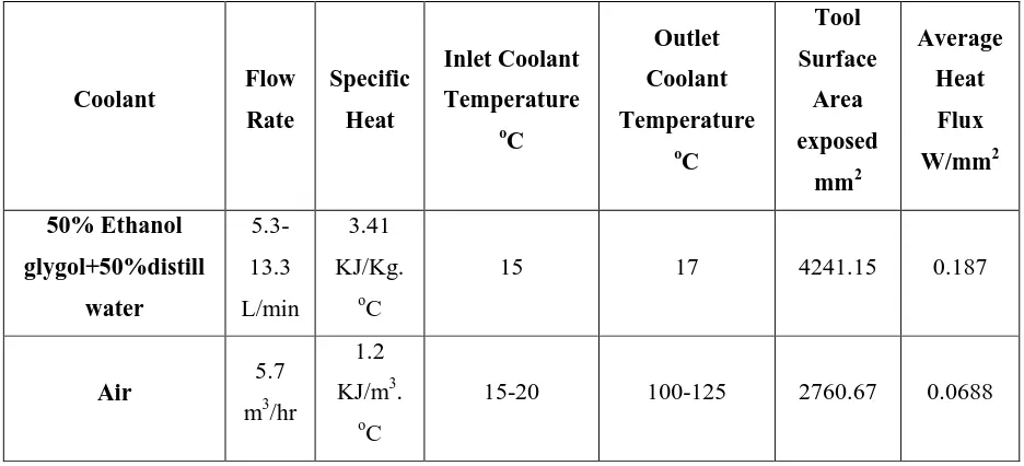
![Figure 2.8: The Cooling system for a PCBN tool for FS welding ferrous alloys [21].](https://thumb-us.123doks.com/thumbv2/123dok_us/678017.570534/41.595.154.453.439.747/figure-cooling-pcbn-tool-fs-welding-ferrous-alloys.webp)
![Table 2.4: Materials welded by PCBN tool [6 P116]](https://thumb-us.123doks.com/thumbv2/123dok_us/678017.570534/44.595.100.503.353.644/table-materials-welded-pcbn-tool-p.webp)
![Figure 2.18: Equilibrium solubility products of carbides and nitrides in austenite [85]](https://thumb-us.123doks.com/thumbv2/123dok_us/678017.570534/69.595.213.418.278.497/figure-equilibrium-solubility-products-carbides-nitrides-austenite.webp)
![Figure 2.21: Micro-hardness data for microstructure constituents in steel. [77 P586]](https://thumb-us.123doks.com/thumbv2/123dok_us/678017.570534/73.595.202.397.91.228/figure-micro-hardness-data-microstructure-constituents-steel-p.webp)
![Figure 2.27: The location of ψ angle and the in-plane stresses .[128 P1404]](https://thumb-us.123doks.com/thumbv2/123dok_us/678017.570534/88.595.223.404.616.739/figure-location-ps-angle-plane-stresses-p.webp)
Related documents
Vetrivel, Effect of Tool Rotational Speed on the Tensile and Microstructural Properties of Friction Stir Welded Different Grades of Stainless Steel Joints, International Journal of
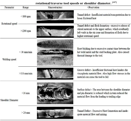
Different welding parameters including tool rotational and tool traverse (linear) speeds were applied to understand their effect on weld seam defects including microcracks and
In order to avoid excessive experimental effort when developing a bobbin tool welded structure, the basic in- teractions of process parameters (welding speed, tool rotation,
Effect of welding speed on microstructures, hardness distribution and tensile properties of the welded joints were investigated by varying the process parameters, defect
Experimental study on the effect of welding speed and tool pin profiles on AA6082-O aluminium friction stir welded butt joints, International journal of
A maximum tensile strength was exhibited by the friction stir welded joints fabricated with the optimized parameters of 2300 r/min rotational speed, 35 mm/min
• SEM observations showed 6-mm-thick DH36 steel can be friction stir welded with a rotational speed limit up to 500 RPM and traverse speed of 400 mm/min
Different welding parameters including tool rotational and tool traverse (linear) speeds were applied to understand their effect on weld seam defects including microcracks and
