Development and evaluation of vision processing
algorithms in multi-robotic systems.
AHMED, M. Shuja.
Available from Sheffield Hallam University Research Archive (SHURA) at:
http://shura.shu.ac.uk/19223/
This document is the author deposited version. You are advised to consult the publisher's version if you wish to cite from it.
Published version
AHMED, M. Shuja. (2013). Development and evaluation of vision processing algorithms in multi-robotic systems. Doctoral, Sheffield Hallam University (United Kingdom)..
Copyright and re-use policy
Learning and Information Services Adsetts Centre, City Campus
Sheffield S1 1WD
1 0 2 1 0 5 8 5 0 5
Sheffield Hallam University Learning and Information Services
Adsetts Centre, City Campus Sheffield S1 1WD
ProQuest Number: 10694103
All rights reserved
INFORMATION TO ALL USERS
The quality of this reproduction is dependent upon the quality of the copy submitted.
In the unlikely event that the author did not send a com plete manuscript and there are missing pages, these will be noted. Also, if material had to be removed,
a note will indicate the deletion.
uest
ProQuest 10694103
Published by ProQuest LLC(2017). Copyright of the Dissertation is held by the Author.
All rights reserved.
This work is protected against unauthorized copying under Title 17, United States C ode Microform Edition © ProQuest LLC.
ProQuest LLC.
789 East Eisenhower Parkway P.O. Box 1346
Development and Evaluation of Distributed Vision
Processing Algorithms in M ulti-Robotic System s
M Shuja Ahmed
A thesis submitted in partial fulfilment of the requirements of Sheffield Hallam University
for the degree of Doctor of Philosophy
Abstract
The trend in swarm robotics research is shifting to the design of more complicated systems in which the robots have abilities to form a robotic organism. In such systems, a single robot has very limited memory and processing resources, but the complete system is rich in these resources. As vision sensors provide rich surrounding awareness and vision algorithms also requires intensive processing. Therefore, vision processing tasks are the best candidate for distributed processing in such systems.
To perform distributed vision processing, a number of scenarios are considered in swarm and the robotic organism form. In the swarm form, as the robots use low bandwidth wireless commu nication medium, so the exchange of simple visual features should be made between robots. This is addressed in a swarm mode scenario, where novel distance vector features are exchanged within a swarm of robots to generate a precise environmental map. The generated map facilitates the robot navigation in the environment. If features require encoding with high density information, then sharing of such features is not possible using the wireless channel with limited bandwidth. So methods were devised which process such features onboard and then share the process outcome to perform vision processing in a distributed fashion. This is shown in another swarm mode scenario in which a number of optimisation stages are followed and novel image pre-processing techniques are developed which enable the robots to perform onboard object recognition, and then share the process outcome in terms of object identity and its distance from the robot, to localise the objects.
Publications
Journals:
(i) Vision Based Object Recognition and Localisation by a Wireless Connected Distributed Robotic Systems. M Shuja Ahmed, Reza Saatchi and Fabio Caparrelli. Electronic Letters on Computer Vision and Image Analysis (ELCVIA), Vol. 11, Issue. 1, Pages: 54-67, 2012. (ii) Distributed Vision Processing in Multi-robotics Organism. M Shuja Ahmed, Reza Saatchi
and Fabio Caparrelli. In Journal of Robotics and Autonomous Systems, Elsevier, (In Review). (iii) Object Classification and Recognition in Distributed Modular Robotic Systems. M Shuja
Ahmed and Reza Saatchi. Electronic Letters on Computer Vision and Image Analysis (EL CVIA), (Re-submitted with Revisions).
(iv) Performance Comparison of Distributed Modular Robotic System vs High Processing Sys tems. M Shuja Ahmed and Reza Saatchi. Electronic Letters on Computer Vision and Image Analysis (ELCVIA), (In Review).
(v) Distributed Vision Processing in Reconfigurable Modular Robotic Systems. M Shuja Ahmed and Reza Saatchi. Journal of Intelligent and Robotic Systems, Springer, (In Review). (vi) Distributed Mosaic Formation and Object Detection in Modular Robotic Systems. M Shuja
Ahmed and Reza Saatchi. Journal of Intelligent and Robotic Systems, Springer, (In Review).
Conferences:
(i) VISION BASED OBSTACLE AVOIDANCE AND ODOMETERY FOR SWARMS OF SMALL SIZE ROBOTS. M Shuja Ahmed, Reza Saatchi and Fabio Caparrelli. In Proceedings of 2nd
' International Conference on Pervasive and Embedded Computing and Communication Sys tems (PECCS), Rome, Italy, 24-26 February 2012, SciTePress, Pages: 115-122.
(ii) SUPPORT FOR ROBOT DOCKING AND ENERGY FORAGING - A Computer Vision Approach. M Shuja Ahmed, Reza Saatchi and Fabio Caparrelli. In Proceedings of 2nd Inter national Conference on Pervasive and Embedded Computing and Communication Systems (PECCS), Rome, Italy, 24-26 February 2012, SciTePress, Pages: 123-128.
(iii) AN EFFICIENT APPROACH TO OBJECT RECOGNITION FOR MOBILE ROBOTS. M Shuja Ahmed, Reza Saatchi and Fabio Caparrelli. In Proceedings of 3rd International Conference on Pervasive and Embedded Computing and Communication Systems (PECCS), Barcelona, Spain, 19-21 February 2013, SciTePress, Accepted for publication.
(v) IMPLEMENTATION OF DISTRIBUTED MOSAIC FORMATION AND OBJECT DE TECTION IN MODULAR ROBOTIC SYSTEMS. M Shuja Ahmed, Reza Saatchi and Fabio Caparrelli. In Proceedings of 3rd International Conference on Pervasive and Embedded Computing and Communication Systems (PECCS), Barcelona, Spain, 19-21 February 2013, SciTePress, Accepted for publication.
EU-FP7 Research Project Replicator: Technical Deliverables
(i) EU-FP7 Research Project Replicator. Year 3 Technical Deliverable. Title: “Distributed Information Gathering and Appearance Based Places Recognition To Perform A Search Op eration By Swarm Of Robots”. M Shuja Ahmed and Fabio Caparrelli. S tuttgart University, Germany, 24 March 2011.
(ii) EU-FP7 Research Project Replicator. Year 4 Technical Deliverable. Title: “Distributed Vision Processing in Multi-Robotic Organism”. M Shuja Ahmed and Fabio Caparrelli. Stuttgart University, Germany, 16 March 2 0 1 2.
EU-FP7 Research Project Replicator: Presentations
(i) Replicator/Symbrion Progress Meeting, INRIA - Paris France, March 2011 (ii) Replicator/Symbrion Review Meeting, Stuttgart University, Germany, May 2011 (iii) Replicator/Symbrion Progress Meeting, York University, United Kingdom, Oct 2011 (iv) Replicator/Symbrion Progress Meeting, Karlsruhe University, Germany, March 2012
(v) Replicator/Symbrion Review Meeting, Stuttgart University, Germany, 3 May 2 0 1 2
(vi) Replicator/Symbrion Review Meeting, Stuttgart University, Germany, 4 May 2012
(vii) Material and Engineering Research Institute (MERI) Day, Sheffield Hallam University, Sheffield, United Kingdom, May 2011.
EU-FP7 Research Project Replicator: Technical Workshops
Contents
Abstract i
Publications ii
Acronyms ix
Symbols xiii
List of Figures xxiii
List of Tables xxiv
Acknowledgements xxv
Declaration xxvi
Disclaimer xxvii
1 Introduction 1
1.1 Aims, objectives and background of the study . . ... 4
1.2 Contribution of T h e s is ... 6 1.2.1 Object Recognition and Localisation in Distributed Robotic Systems . . . . 8
1.2 .2 Computer Vision Support for Robot Docking and Energy F o rag ing ... 10
1.2.3 Environment Mapping by Distributed Multi-Robotic S y s te m ... 11 1.2.4 Distributed Object Recognition and Visual Information Gathering in a
1.2.5 Distributed Object Classification and Recognition in a Robotic Organism . 11
1.3 Thesis Outline ... 12
2 Literature Review 15 2 .1 Com m unication... 21
2 .2 Obstacle Avoidance ... 23
2.3 Energy Foraging and Vision Support for D o ck in g... 24
2.4 Localisation . ... 24
2.5 Appearance Based Object Recognition ... 28
2.6 M ulti-robot Environment M ap p in g ... 32
2.7 Distributed Processing in Robotic Organism . ... 33
2.8 C onclusions... 35
3 Hardware and Software Requirements 36 3.1 Hardware Requirements for Swarm Mode Scenarios... 36
3.1.1 Swarm Robot U n i t s ... 37
3.1.2 Hardware for Swarm Com munication... 39
3.1.3 Robot Tracking Cameras ... 40
3.2 Hardware Requirement for Organism Mode Scenarios... 41
3.2.1 Analog Devices - Blackfin P ro c e s s o r . . 41
3.2.2 Blackfin Evaluation Board EVAL-BF5xx... 44
3.2.3 Blackfin Extender Board EXT-BF5xx-Camera 44 3.2.4 Blackfin Experimental Board ... 45
3.2.5 CMOS Camera Sensor ... 46
3.2.6 Robot Base and Motor Control Board ... 46
3.2.7 Onboard C om m unication... 47
3.2.8 Navigation b o a rd ... 48
3.3 Selection of Operating System (Robot F irm w are)... 49
3.4 Conclusions ... 51
4.2 Embedded Vision Algorithms . ... 62
4.2.1 YUV to Colour Image C o n v e rsio n ... 62
4.2.2 Colour to Grey Scale Conversion ... . v63
4.2.3 Grey Scale G ra d ie n t... . 64
4.2.4 Colour G r a d ie n t... 65
4.2.5 Grey Scale and Colour Image S egm entation... 66
4.2.6 Colour Blob Detection ... 6 6 4.2.7 Image Erosion ... 6 8 4.2.8 Image D ila tio n . . 68
4.3 Vision Based Obstacle A voidance... 69
4.3.1 Approaches To Obstacle Avoidance... . 70
4.3.2 Experimental Results ... 77
4.4 Energy Foraging ... 8 6 4.4.1 Expermental Results ... 87
4.5 Vision Based Docking Support . . : . . . 8 8 • 4.5.1 Blob Detection of Red LEDs in ON State ... 90
4.5.2 Obtaining the Statistics of Red LED Blobs . . . ... 94
4.5.3 Classification of Red LED blobs ... 94
4.5.4 Control Algorithm to Approach the B lo b s ...•... 95
4.5.5 Experimental Results ... 97
4.6 C onclusions... 102
5 M ulti-Robot Localisation and Tracking System 103 5.1 Camera Calibration ... 104
5.2 Visual Localisation and Tracking System ... I l l 5.2.1 Colour Blob Extraction . . . ... 112
5.2.2 Extraction of Blobs S ta tis tic s... 113
5.2.3 Template Matching and Pattern R eco g n itio n ... 113
5.2.4 Multi Camera Based Robot Tracking . . . ... 116
5.3 Multi-Robot Visual G u id an ce... 120
6 Distributed Vision Processing in M ulti-Robotic Swarm 127
6.1 Communication among Swarm of R o b o t s ... 128
6.2 Vision Based Object Recognition and Localisation by Multi-Robotic Systems . . . 128
6.2.1 Processor Specific O ptim isation... 133
6.2.2 Image Pre-processing... . ; . . 134
6.2.3 Multi-resolution A n a ly s is ... 135
6.2.4 Experimental Results . . . ... 138
6.3 Environment Mapping by Distributed Multi-robotic S y ste m ... 149
6.3.1 Methodology - Environment Mapping . . . . ... 151
6.3.2 Experimental Results ... 159
6.4 C onclusions... 165
7 Distributed Object Recognition and Information Gathering in a M ulti-Robotic Organism 166 7.1 Communication in the Robotic Organism 169 7.2 Tasks Distribution for Distributed Object Recognition and Information Gathering 173 7.2.1 Communication Awareness within the Robotic O rg a n is m ... 173
7.2.2 Distributed Object R ecognition... 176
7.2.3 Distributed Information G a th e rin g ... . . 178
7.3 Experiments with Robotic O rg an ism . . . 185
7.4 C onclusions... ... . ... 200
8 Distributed Object Classification and Recognition in a Robotic Organism 201 8.1 Multi-processor Robotic O rg a n ism ... 203
8.2 Communication within the Robotic Organism ... 204
8.3 Vision Task Distribution for Distributed Object Classification and Recognition . . 205
8.3.1 Module 1: Information Pre-processing . ... 206
8.3.2 Module 2: Object Classification... 207
8.3.3 Module 3: Object R ec o g n itio n ... 210
8.3.4 Module 4: Vocabulary of Visual Words ... 211
8.5 Performance Comparison of Distributed Modular Robotic System versus High Pro
cessing S ystem s... 221
8.5.1 Object Recognition - High Processing S y ste m ... . 222
8.5 .2 Performance Comparison ... 223
8 .6 C onclusions . . : ... 231
9 Conclusions &: Future Work 233 9.1 C onclusions... 233
Acronyms
CMOS Complementary metal oxide semiconductor
YUV Y luma,U chroma blue,V chroma red
LEDs Light emitting diodes
WiFi Wireless fidelity
A8 Adjacency in eight directions
FOE Focus of expansion
SURF Speeded up robust features
2D Two dimensional
3D Three dimensional
TCP Transmission control protocol
UDP User datagram protocol
DLT Divisible load theory
IUB Inter-national university Bremen
FPS Frame per second
MBPS Mega bits per second
CORBA Common object request broker architecture
TEAR (Transmission control protocol) emulation at receiver
MANET Mobile adhoc network
PERA Probabilistic emergent routing algorithm
RSCA Robot software communications architecture
MAVs Micro aerial vehicles
IR Infra red
RFID Radio frequency identification
POM DP Partially observable Markov decision process
SIFT Scale-invariant feature transform
SVM Support vector machines
CRF Conditional random fields
PCA Principle component analysis
KNN K nearest neighbour
RANSAC Random sample consensus
kd-tree K-dimensional tree algorithm
MIPS Mega instructions per second
WLAN Wireless local area network
GNU A recursive acronym for ” GNU’s Not Unix!”
JTAG Joint test action group
SDRAM Synchronous direct random access memory
GPL General public license
WEP Wireless encryption protocol
ADSP Advanced digital signal processor
DSP Digital signal processor
RISC Reduced instruction set computing
MMU Memory management unit
SIMD Single instruction multiple data
ALU Arithmetic logic unit
MHz Mega hertz
I/O Input and output
DMA Direct memory access
SPORTs Synchronous serial ports
PPI Parallel peripheral interface
CMBF Core module Blackfin
DAC Digital to Analog converter
SYMBRION Symbiotic Evolutionary Robot Organisms
REPLICATOR Robotic Evolutionary Self-Programming and Self-Assembling Organisms
OV7670 Omni-vision 7670 camera sensor
SPI Serial peripheral interface bus
MAC Media access control
GPIO General purpose input output
UART Universal asynchronous receiver/transm itter
USB Universal serial bus
PWM Pulse width modulation
VGA Video graphics array
GPS Global positioning system
OS Operating system
uCLINUX Micro controller Linux
FPU Floating point unit
R Red channel
G Green channel
B Blue channel
TTC Time to contact
QVGA Quarter video graphics array
A* Path search algorithm
OPEN CV Open source computer vision library
Symbols
Ex Partial derivatives in x-axis
Ey Partial derivatives in y-axis
Et Partial derivatives of time
ax x component of camera focal length
Oiy y component of camera focal length
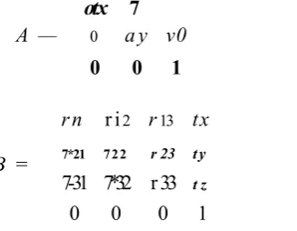
7 Skew coefficient between x and y axis of image
(u q, v q) Principal point of the camera.
r11 Parameter of camera rotation matrix
r i2 Parameter of camera rotation matrix
r i3 Parameter of camera rotation matrix
r2i Parameter of camera rotation matrix
r*22 Parameter of camera rotation matrix
7*23 Parameter of camera rotation matrix
rsi Parameter of camera rotation matrix
7*32 Parameter of camera rotation matrix
x parameter of camera translation matrix
y parameter of camera translation matrix
z parameter of camera translation matrix
Orientation
Delta
3D world points
2D image points
Camera matrix
Scale factor
x coordinate of world point
y coordinate of world point
z coordinate of world point
Camera intrinsic matrix
Rotation camera matrix
Translation camera matrix
Camera extrinsics
x-coordinates of the features points from first image
y-coordinates of the features points from first image
x-coordinates of the features points from second image
y-coordinates of the features points from second image
List of Figures
1.1 (a) Ants trying to move heavy prey [5]. (b) Robots search for the big red object in
the environment [6]. (c) Swarm of robots moving the object collectively [6]... 2
1.2 (a) Ants forming a bridge to facilitate other members for carrying food to the colony [9]. (b) Robots physically joining together and forming a bridge [6]. ... 3
1.3 Multi-Robotic Systems (a) Symbrion [7] (b) Replicator [8]... ... 7
1.4 Scenario for distributed vision processing among swarm of robots... 9
1.5 Chapters organisation. ... 14
2 .1 Swarm of self assembled robots moving over an obstacle [7]. ... 15
2.2 Single robot from a team, detecting and tracking a coloured ball to perform dis tributed map building [18] 16 2.3 Active vision agents based target detection and tracking [23]. ... 17
2.4 Processing stages for remotely sensed images [28]... 18
2.5 Image processing stages for image mining system [27]... . 19
2 .6 An omni-directional vision based formation of mobile robots [29]. ... . 20
2.7 Ants following artificial pheromones [112]... . . 21
2.8 Robot moving around 7x7 WiFi grid [36]... 22
2.9 RFID tags attached to walls for robot localisation [50]... 25
2.10 Negative image of a lamp on ceiling used for robot localisation [53]... 26
2.1 1 Some example markers from cantag [57]... 27
2 .1 2 SURF features detected in omni-directional camera image [59]... 28
2.14 (a) Image 1. (b) Image 2. (c) Reconstructed image from 20 dimensional eigen
vectors. [70]... 31
3.1 (a) REPLICATOR robot [8]. (b) SRV1 blackfin robot by surveyor corporation [89]. (c) Swarm of SRV1 robots ... 3.2 Linksys wireless access point [104]... . 3.3 Logitech webcam Pro 9000 [105]. ... . . . . . . 3.4 Blackfin CM-BF537E core [91]. ... 3.5 Evaluation board EVAL-BF5xx [100]... 3.6 Blackfin extender board EXT-BF5xx-Camera [101]... 3.7 Blackfin experimental board “EXT-BF5xx-EXP” [106]... 3.8 (a)Ov7670 camera sensor [107]. (b) Flexi cable [108]... 3.9 (a) Robot base for the organism [109]. (b) Motor control board [109]... 3.10 (a) Lantronix matchport 802.11b/g WiFi [110]. (b) Ethernet communication cable. 3.11 Navigation board M3 [111]. ... ... 3.12 Robot o rg a n is m ... ... ... 4.1 Image captured by the robot vision system... 53
4.2 Robot images used for calibration: image 1 (left) and image 2 (right) ... 55
4.3 Robot Images used for calibration: image 3 (left) and image 4 (right) ... 55
4.4 Robot images used for calibration: image 5 (left) and image 6 (rig h t)... 56
4.5 Robot images used for calibration: image 7 (left) and image 8 (rig h t)... 56
4.6 Robot images used for calibration: image 9 (left) and image 10 ( r ig h t) ... 56
4.7 Robot images used for calibration: image 11 (left) and image 12 (right) ... 57
4.8 Robot images used for calibration: image 1 3 ...'... 57
4.9 Calibration results: Re-projections on image (left) and enhanced image (right) . . 58 4.10 Calibration results: Re-projections on image (left) and enhanced image (right) . . 59 4.11 Calibration results: Re-projections on image (left) and enhanced image (right) . . 60 4.12 Calibration results: Re-projections on image (left) and enhanced image (right) . . 61 4.13 Calibration results: Re-projections on image (left) and enhanced image (right) . . 62 4.14 Image obtained after YUV to colour image conversion... 63
4.15 Image obtained after colour image (left) to greyscale image (right) conversion. . . . 63 4.16 Image coordinates and Sobel operator for gradient in x and y direction... 64 4.17 Greyscale image (left) and gradient image (right) obtained from BF537E processor. 64 4.18 Colour image (left) and gradient image (right) obtained from BF537E processor. . 65 4.19 A8 adjacency. Directions in which region can grow is shown by arrows. ... 6 6
4.20 Colour image, (left) and segmented image (right) obtained from BF537E processor. 67 4.21 UV plane providing the chrominance information... 67 4.22 Colour input image (left) and processed image (right) showing detection of red colour
blobs... 68
4.23 Input image (left) and processed image (right) obtained after erosion. . . . 6 8
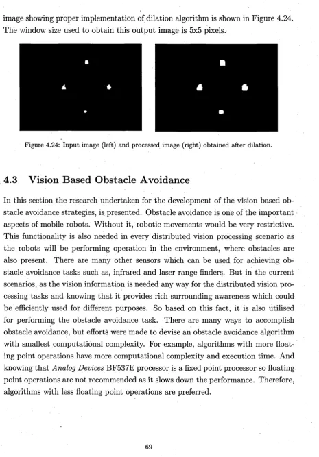
4.24 Input image (left) and processed image (right) obtained after dilation... 69 4.25 (a) Colour input image, (b) Processed image obtained after applying segmentation.
(c) Initial ground map isolated from obstacle’s, (d) Ground map visible to the robot vision system. . . .•... 71 4.26 The estimates of three partial derivatives Ex, Ey and E t of image brightness at the
centre of the cube are each obtained from the average of first differences along four parallel edges of the cube. Here the index ’y’ corresponds to the x direction in the image, the index V to the y direction and index lies in the time direction. . . . 74 4.27 Focus of expansion (FOE)... 76 4.28 Path finder approach to obstacle a v o id a n c e ... 77 4.29 Test platform for SRV-1 robot with obstacles placed on it... 78 4.30 In left image robot environment and placement of obstacles are shown. In right
image, the path followed by the robot is shown... 79 4.31 Processed images obtained from segmentation based obstacle avoidance algorithm.
Steps 1 and 2 ... 80
4.32 Processed images obtained from segmentation based obstacle avoidance algorithm.
Steps 3 and 4 ... 80
4.34 Processed images obtained from segmentation based obstacle avoidance algorithm. Steps 7 and 8 ... ...: ... 81
4.35 Processed images obtained from segmentation based obstacle avoidance algorithm. Steps 9 and 10 ... ... 82 4.36 Processed images obtained from segmentation based obstacle avoidance algorithm.
Steps 11 and 12 . ... 82 4.37 Processed images obtained from segmentation based obstacle avoidance algorithm.
Steps 13 and 1 4 ... 83 4.38 Path followed by the robot when segmentation based obstacle avoidance is used. . 83 4.39 Optical flow field obtained between two consecutive images... 84 4.40 Zoom-in version of the optical flow field shown in Figure 4 .3 9 ... 85 4.41 Path followed by the robot when optical flow based obstacle avoidance is used. . . 85 4.42 Image showing the detection of red colour blobs when colour blob detection algo
rithm is used... 87
4.43 Path followed by the robot to locate the energy resources... 8 8
4.44 Image showing LEDs used for docking operation . . . ... 89
4.45 U image of Figure 4.44 91
4.46 V image of Figure 4.44 92
4.47 O utput of colour blob detection algorithm . ... 92
4.48 Y image of Figure 4 .4 4 . 93
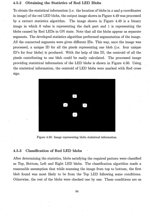
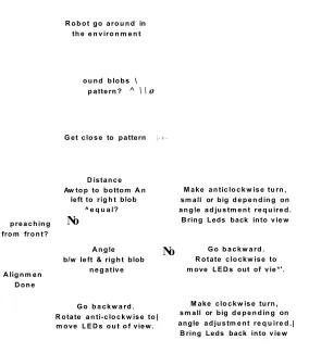
4.49 Blobs resulting from red LEDs in ON s t a t e . ... 93 4.50 Image representing blobs statistical information... 94 4.51 Search field for neighbouring blobs... 95 4.52 Flow diagram of control algorithm. ... 96 4.53 Robot approaching the LEDs for docking from left side with reference to the LEDs
location. ... 97 4.54 Robot approaching the LEDs for docking from right side with reference to the LEDs
4.57 Trajectory followed by the robot in experiment 4. . . . ... 100 4.58 Pose of the robot after performing alignment... 101 4.59 (a) Swarm of robots starting collective search for docking port, (b) One robot finds
the docking port and the rest quit mission. ... 102
5.1 Image 1 (left) and image 2 (rig ht)... 105 5.2 Image 3 (left) and image 4 (rig h t)... 106 5.3 Image 5 (left) and image 6 (rig h t)... 106
5.4 Image 7 (left) and image 8 (righ t)... 106
5.5 Image 9 (left) and image 10 (right) ... 107 5.6 Image 11 (left) and image 12 ( r i g h t ) ... 107 5.7 After grid points selection: image 1 (left) and image 2 (right) ... 107
5.8 After grid points selection: image 3 (left) and image 4 ( r ig h t) . 108 5.9 After grid points selection: image 5 (left) and image 6 (right) ... 109
5.10 After grid points selection: image 7 (left) and image 8 (right) ... 109
5.11 After grid points selection: image 9 (left) and image 10 (right) ... 110 5.12 After grid points selection: image 11 (left) and image 12 (right) . . . 110
5.13 Reprojected 2D grid points. . ... I l l 5.14 Fiducial markers tem plate... 112 5.15 Color blobs extraction... . . 113 5.16 Pattern recognition process, (a) Window around the selected blob, (b) Selecting
. the expected tail blob, (c) Search line from tail to the head blob along which cover blob will be searched, (d) Search line along which cover blob is searched for ‘final validation of the pattern. ... 114 5.17 Determining the location and orientation of the four robots. . . 115 5.18 Ceiling mounted camera set-up for robot tracking. . . ... 117 5.19 Collective tracking of robots from ceiling mounted cameras... 118 5.20 Collective tracking of robots from ceiling mounted cameras . 119 5.21 Robot arena used for the visual guidance of the robots... 121 5.22 Image showing the shortest path to the target location for all the robots on the grid
5.23 Test 1: Positions of the robots in the arena before the test started. . . 122
5.24 Test 1: Robots path to the target location on the grid map. . ... 123 5.25 Robot 1 colliding the obstacle b oundary... 123 5.26 Test 1: Robots reached the target location successfully... 124 5.27 Test 2: Positions of the robots before the test begin... . . ... 124 5.28 Test 2: Shortest path to the target location on the grid m ap . 125 5.29 Test 2: Robots reached the target location successfully... 125
6.1 Scenario where group of robots performing search operation to find the object of interest. . . ... 131 6.2 Processor specific optimisation to reduce execution time. ... 134 6.3 Image pre-processing to reduce the amount of data to process. ... 136 6.4 Scale-space image pyramid... 137 6.5 Resolution switching based on distance to object... 138
6 .6 Execution timing - SURF vs Optimised SURF... 139
6.7 Recognition rate - SURF vs Optimised SURF. . ... 141
6 .8 Objects used in training to extract SURF fe a tu re s... 141
6.9 Images from 16 poses of the 3D object... 142 6.10 Position of robots and objects of interest before experiment is performed...143 6.11 Position of the robots when they recognise the object in the environment. . . . 143
6 .1 2 Sequence of Robot 1 positions when it detected and then missed object 3... 144
6.13 Sequence of robot 2 positions when it detected and then missed object 1... 145
6.14 2D and 3D objects used for experiment... 146 6.15 Position of robots before experiment... 147 6.16 All objects are localised by using information from the team of robots and visual
tracking system collectively. . . 148
6.17 Error observed in localising object... 149 6.18 Input image used for boundary detection...' . ... 152 6.19 Segmented image... 153 6.20 Boundary vector plotted on the segmented image... 153
6.22 Zoom-in information of robot 1 position... 155 6.23 Profile between distance from object (pixels) and scale factor... . 156
6.24 Mapping process... . 157
6.25 (a) Distance vector from robot 1 mapped To coordinates of visual tracking system. (b) Robot tracking image from second ceiling mounted camera, (c) Global map generated using the two ceiling mounted cameras... 159 6.26 Zoom-in version of Figure 6.25a... . 159
6.27 Experiment 1: Visual tracking system (a) Left camera, (b) Right camera. . . . ' . . 160
6.28 Experiment half finished: (a) Left camera, (b) Right camera, (c) M ap. 161 6.29 Mapping error caused by the orientation error... 162 6.30 Experiment 2: Visual tracking system (a) Left camera, (b) Right camera. 163
6.31 Experiment 2 half finished: (a) Position of robots in left camera after half of the experiment is finished, (b) Position of robots in right camera after half of the experiment is finished, (c) Progress on map generation after half of the experiment is finished, (d) Experiment 2 final map generated... 164
6.32 Experiment 3: (a) Left camera image from visual tracking system, (b) Right camera image from visual tracking system... 164 6.33 Experiment 3 final map generated... 165
7.1 Robotic organism scenario... 167 7.2 Robotic organism recognising the object in the environment. . ... 168 7.3 Robotic organism gathering the visual information and making mosaic...169 7.4 Communication set-up between robotic modules in the organism. . . ... 170 7.5 Communication network layers... 170 7.6 Application interfaced to TC P/U D P layer. ... 171 7.7 Application interfaced to ethernet layer... 171 7.8 Ethernet frame (IEEE 802.3 standard)... . . 172 7.9 Example Replicator robots participating to form an organism [8] . ... 174
7.10 Replicator robotic organism from three robots [8]. . 174
7.13 Distributed information gathering - task communication. ... ... 7.14 Image re-projection on common plane... . 7.15 Images re-projection using product of homographies... 7.16 Distributed information gathering - vision processing phases. ... 7.17 Slave 2 :Four step processing phases - Step 1 and 2... ... ... 7.18 Slave 2 :Four step processing phases - Step 3 and 4... ...
7.19 Multi-processor robotic organism...
7.20 Target 2D objects... 7.21 Obstacle avoidance referesh time: Single robot vs robot organism... 7.22 Timing analysis of object recognition algorithm with varying object features. . . . 7.23 Object recognition: single robot vs distributed processing... 7.24 Unknown 2D objects... 7.25 Test arena for distributed vision processing in organism mode. . . ... 7.26 (a) Position of the organism when the test begin, (b) Position of the robot when
it has identified the target object 2. (c) Identified location of the target object 2 in
the image... ... 7.27 Object 2 surrounding scanned by the organism...
7.28 Images grabbed by the organism to form a mosaic . . . 7.29 Mosaic of images scanned around object 2. . ."... . 7.30 Mosaic of images scanned around object 2. ... 7.31 Object detection in complete mosaic... 7.32 Trajectory made by the organism and location from which mosaics were generated. 7.33 (a) Mosaic from the images scanned around object 1. (b) Segmentation based ground
elimination, (c) Objects detection in mosaics. ...
7.34 (a) Mosaic from the images scanned around object 3. (b) Segmentation based ground elimination, (c) Objects detection in mosaics... 7.35 (a) Erroneous image stitching, (b) Second last image, (c) Last image...
8.1 REPLICATOR robotic organism [2]...
8.2 Communication within the multi-processor s y s te m ... 8.3 Vision task distribution...
8.4 (a) Low resolution image for close object, (b) High resolution image for far object. 208 8.5 Classification probability. ... ... ... ■. 209
8 .6 Feature space clustering and histograms generation... 21 2
8.7 Classification and recognition ID ... ... ... . 214
8 .8 Classification probability. ... 215
8.9 Processor usage. ... 216
8.10 Memory usage. ... 217 8.11 Frame per second - Four processors system. ... 219 8.12 Frame per second - Single processor robot... 220 8.13 Classification probabilities with increasing number of objects in the vocabulary. . . 221
221
221
8.16 Pioneer-3AT robot. ... . 22 2
List of Tables
6.1 Object Localisation Information
Acknowledgments
Declaration
Sheffield Hallam University
Materials and Engineering Research Institute
The undersigned hereby certify that they have read and recommend to the Faculty of Arts, Computing, Engineering and Sciences for acceptance a thesis entitled “D ev elo p m en t a n d E val u a tio n o f D is trib u te d V ision P ro ce ssin g A lg o rith m s in M u lti-R o b o tic S y stem s” by M S h u ja A h m ed in partial fulfilment of the requirements for the degree of Doctor of Philosophy.
Date: ______ 2013
M Shuja A hm ed__________ :__
Director of Studies: Dr. Reza Saatchi A J L L
Disclaimer
Sheffield Hallam University
Materials and Engineering Research Institute
Author: M Shuja Ahmed
Title: Development and Evaluation of Distributed Vision Processing Algorithm s in M ulti-Robotic Systems
Department: M aterial and Engineering Research Institute
Degree: PhD Year: 2013
Permission is herewith granted to Sheffield Hallam University to circulate and to have copied for non-commercial purposes, at its discretion, the above title upon the request of individuals or institutions.
THE AUTHOR ATTESTS THAT PERMISSION HAS BEEN OBTAINED FOR THE USE OF ANY COPYRIGHTED MATERIAL APPEARING IN THIS THESIS (OTHER THAN BRIEF EXCERPTS REQUIRING ONLY PRO PER ACKNOWLEDGEMENT IN SCHOLARLY W RIT ING) AND THAT ALL SUCH USE IS CLEARLY ACKNOWLEDGED.
Signature of Author:
Chapter 1
Introduction
A major research in the field of robotics is focused on moving the robots and vehicles autonomously in an unknown environment and taking intelligent decisions (e.g., grab object after recognising) to accomplish specific tasks. After achieving excellence in moving individual robots autonomously, the trend in the robotic research has shifted to collaborative achievement of tasks in multi-robotic environment, where multiple small size robots work together to achieye common objectives and goals [1] [2] [3] [4]. This has led to the concept of swarm robotics. The idea of swarm robotics is based on swarm intelligence which is inspired from the social behaviour exhibited by animals, specially insects. One example in the nature showing collective behaviour is the manner ants pick up the prey together, which is many times heavier than their own weight and bring this food back to their colony. This is shown in Figure 1.1a. The same behaviour when exhibited by the swarm of robots, is shown in Figure 1.1b, where a number of small size robots are collectively searching for a big Red coloured object. Once the object is found, then the robots have to move it. The object is too heavy for a single robot to move. Hence, a robot swarm needs to cooperate with each other for moving it. This cooperative behaviour exhibited by the robot swarm for moving the object collectively towards the light source is shown in Figure 1.1c.
Figure 1.1: (a) Ants trying to move heavy prey [5]. (b) Robots search for the big red object in the environment [6]. (c) Swarm of robots moving the object collectively [6].
the nature as shown in Figure 1.2a. This intelligent practice is being adopted by a type of ants, commonly found in Central and South America. These ants categorise among themselves and select the members having suitable body size to fill the gaps between the stems and eventually form a bridge. This cooperative behaviour by the ants facilitates other ants to carry food back to their colony.
chal-Figure 1.2: (a) Ants forming a bridge to facilitate other members for carrying food to the colony [9]. (b) Robots physically joining together and forming a bridge [6].
lenges of efficient knowledge sharing among multiple robots, so that the collective and cooperative achievement of the task can be made. In the field of robotics, the use of inexpensive vision sensors provides rich surrounding information which can be used effectively to enhance the robot’s knowledge about the environment. The use of these sensors alone enables the solution to many problems in robotics (e.g obstacle avoidance, object detection, scene understanding and pattern recognition). Although integration of these vision sensors in swarm robotics has led researchers to use the power of computer vision technology, but at a cost of increased com putational complexity as these sensors generate huge amount of data that require processing. In swarm robotics, this computational complexity problem turns out to be worst as the target robots have very limited memory and processing power. In such systems, a single robot unit alone has limited processing power, but the swarm system as a whole is rich in processing resources, which are distributed among the whole system. So the computationally complex nature of the vision processing algo rithms makes the vision processing task the best candidate to be distributed in the rich processing environment of the swarm systems. This distribution of vision in formation in swarm systems introduces the concept of distributed vision processing among multi-robotic systems [12].
1.1 Aims, objectives and background of the study
visually guided and trying to cooperate with each other by sharing the knowledge they gained about the environment, this makes the scenario quite interesting and challenging. So when a swarm of robots is moving in an environment to achieve a certain task collectively, ideally the swarm is expected to achieve the task more quickly as compared with a single robot, of-course subject to how efficient knowledge sharing and task distribution is performed by the robots. The task distribution can be performed on equal level that is, all the robots are given the same task. For example, to perform energy foraging [2], searching and localising important objects in the environment or mapping the environment. Or it can be on demand basis that is, the robots which are performing computationally heavy tasks dynamically determine when they want to distribute the tasks and may ask for help from other robots which are less busy.
Hence, distributed processing in the swarm robotic systems is a very active area of robotic research in which researchers have solved many problems by sharing the knowledge learned from different on-board sensors. But most of these research outcomes are based on computer simulations, with very little work done using real multi-robotic systems. However, distributed vision processing in swarm systems is a new and open research area in which detailed research is required. The use of real multi-robotic system for performing the distributed vision processing task makes this research area interesting and more challenging.
1.1 Aims, objectives and background of the study
The main aim of this research is to address the manner distributed vision processing could be achieved in a multi-robotic system which could work in swarm and organism modes. The multi-robotic system, in either swarm and organism form, is itself a distributed embedded system environment, with processing and energy resources, very limited in a single robot unit, but rich in terms of the whole system. So, for distributed vision processing in swarm and the organism form, a number of distributed vision processing scenarios are developed with the following objectives.
1.1 Aims, objectives and background of the study
in swarm and the organism form. The vision processing algorithms are required to provide high frame processing rate (i.e., 40 frames per second or higher), so that they can provide real time response in the vision processing scenarios.
(ii) Development and implementation of light weight vision based obstacle avoid ance algorithms, so that when the robots are moving in the environment, they avoid colliding with the obstacles.
(iii) Development of efficient vision based multi-robot docking support so that tran sition from the swarm to the organism can be facilitated.
(iv) Provision of vision based object recognition functionality to the robots. This requires the development and implementation of an efficient object recognition approach suitable for executing on a small size robot.
(v) Provide vision based surrounding awareness (e.g., by environment mapping and objects localisation) to the robots, which helps the robots to navigate in the environment.
(vi) Efficient utilisation of memory and processing resources in a robotic organism by distributing the vision processing load among multiple processing modules. This requires the development and implementation of vision based tasks (such as, object classification, recognition and surrounding visual information gath ering) in a modular fashion. The modular implementation of vision processing tasks facilitate in distributing the vision processing load, and provides higher frame processing rate, which helps the robotic organism to show quick response to its observations (i.e., information from vision sensor).
1.2 Contribution of Thesis
organism. After performing various image processing algorithms, on the gathered information, it can be used in the visual guidance of the swarm of robots so that they can accomplish some specific tasks collectively. As every robot in the swarm gets independent processing resources, and considering that the vision processing tasks can be computationally expensive for miniature size robots, so a need to efficiently utilise the processing resources, in individual robots and also in assembled robotic organism, naturally arises.
This PhD research addresses the different vision based tasks of REPLICATOR project and presents the scenarios which essentially simulate how vision distribution can be achieved when the robots are in the swarm and organism forms.
Apart from the REPLICATOR project, the outcome of this research has applica tions in many diverse fields. It can be applied to provide robotic support to perform search operations in a hazardous environment, where sending humans to accomplish the tasks may involve risks or dangers to life (e.g a gas leak in a factory). It can be used to get robotic help in searching for survivals after natural disasters such as an earthquake. A very interesting application could be in planetary explorations, e.g a mission to Mars. In planetary explorations, a mission failure is generally not considered affordable and can cause huge sums of money to be lost, so the deploy ment of swarm of robots reduces the chances of a failure following the fact that, the malfunctioning of a single robot will not put the whole mission at risk.
The fact that, swarm robotics is an emerging field and most of the research performed is still limited to swarm intelligence theories and simulations, hence there is still a long way to go to achieve excellence in this field.
1.2 Contribution of Thesis
1.2 Contribution of Thesis
in distributed multi-robotic systems. The main contributions of this research are outline below.
Figure 1.3: Multi-Robotic Systems (a) Symbrion [7] (b) Replicator [8].
(i) Development of multi-processor robotic system which simulates the processing and memory resources of a robotic organism.
(ii) Development of a library of vision processing algorithms optimised for target embedded system based on Analog Devices Blackfin processor.
(iii) Distributed object recognition and localisation by wireless connected swarm robotic system. This approach presents novel contributions (i.e., efficient im age pre-processing and distance based resolution switching techniques) in the current state of the art appearance based recognition algorithm (i.e., SURF fea tures based recognition). The developed approach makes it possible to achieve robust recognition on small size robots with limited onboard memory and pro cessing resources.
(iv) A novel distance vector features based environment mapping solution by a swarm of robots. This distance vector feature is easy to compute and share among swarm of robots, without overloading the wireless communication net work, and hence, plays a vital role in environment mapping.
1.2 Contribution of Thesis
robotic organism. This provides surrounding awareness to the robotic organism and facilitate it in navigating in the environment.
(vi) A novel approach to object classification and recognition in a robotic organism in modular fashion. A vision processing architecture is developed which im plements a modular object classification and recognition approach and shows that, the collective use of the processing and memory resources in a robotic organism can provide performance comparable to bigger robots equipped with high processing systems.
In order to clearly highlight the achievements, the above described contributions of the thesis are demonstrated in terms of distributed vision processing scenarios in swarm and the organism form. These swarm and organism mode scenarios are described one by one below, and shows the effectiveness of the contributions in these scenarios.
1.2.1 Object Recognition and Localisation in D istributed R obotic Sys tem s
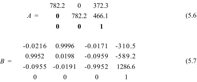
The first scenario addressed is “Object Recognition and Localisation in Distributed Multi-Robotic Systems”. For this scenario, as the robots are expected to come across a number of obstacles during the operation, so first of all, a number of vision based obstacle avoidance techniques are researched. A novel and very light weight vision based obstacle avoidance technique is developed which could run in parallel with other vision based tasks, while consuming low processing power (i.e., the execution time of obstacle avoidance algorithm is 22 msec). In this scenario, a set of miniature size robots, with limited on-board processing capabilities and resources, are used to recognise the objects of interest and then localise them in an unknown environment. The overall picture of a targeted scenario is presented in Figure 1.4, where a swarm of network connected robots is gathered near an assembly point and they have to recognise and localise the objects of interest (i.e. Cups images) in the environment.
1.2 Contribution of Thesis
m
V>
Swarm of Robots
■
4* jpi
[image:40.612.121.494.49.289.2]Assembly j I I
I I ^ 'nt |
} * » •Vs
fa
Battery Charging Point
D ifferent C olors for D irectional Inform ation
N
w e
s
Target Objects
In
v
* »•r *i
jam
iS lW B
Figure 1.4: Scenario for distributed vision processing among swarm of robots.
1.2 Contribution of Thesis
be executed on small size robots and can provide frame processing rate of at least 1 FPS (frame per second). The reduced execution time is achieved by performing the system specific optimisation and redundant data elimination from the images. And for increasing the recognition performance with respect to the distance from the target object, a novel resolution switching technique is developed. The second con tribution of this scenario is the development of novel approach for the localisation of the objects of interest in the environment by fusing the visual features generated by the distributed multi-robotic systems.
1.2.2 Computer Vision Support for R obot Docking and Energy Foraging
1.2 Contribution of Thesis
transition stage. '
1.2.3 Environment M apping by D istributed M ulti-R obotic System
In this scenario, a vision based mapping of the unknown environment by the dis tributed multi-robotic system is addressed, where the robots are provided with the localisation information from a ceiling mounted, camera system. Different from other robotic systems that rely mostly On sensors (such as laser range finders) which are very expensive and can not be used with miniature size robots, the technique addressed in this scenario solely relied on the vision information. The research ad dressed in this scenario presents a novel method based on very simple visual features, which could be easily shared by the swarm of robots using a wireless communication channel. Using these visual features the robots collectively generated a sufficient environmental map which could be effectively used for the robot navigation.
1.2.4 D istributed Object Recognition and Visual Inform ation G athering in a M ulti-R obotic Organism
Different from the previous scenarios, in this scenario, the distributed vision pro cessing is performed in the organism mode. In the field of swarm or modular robotic systems, this is the first time, distributed vision processing research is performed using the distributed memory and processing resources of a robotic organism. In the proposed scenario, a new method is introduced which is adopted by the robotic or ganism to perform vision based obstacle avoidance, efficient object recognition, and visual information gathering in a distributed fashion. In the robotic organism, the visual information is processed by multiple processing units at different stages and finally, the information is gathered in the form of image mosaics. These image mo saics provided the necessary awareness about the surrounding of the target objects to the robotic organism.
1.2.5 D istributed Object Classification and Recognition in a R obotic Organism
This scenario presents a novel method which implements a vision based object classi fication and recognition approach in a modular fashion, using the distributed memory and processing resources of a robotic organism, comprising of four robotic modules.
1.3 Thesis Outline
given training for, but also facilitated the organism to learn new objects. This ap proach established a feedback mechanism between the different computing modules in the organism, and facilitated an efficient utilisation of the distributed resources. In this scenario, a detail comparative analysis is also performed with reference to the high performance processing systems. It is found that, the efficient utilisation of the processing, memory and communication abilities of the organism, can provide performance which could compete with high processing systems.
1.3 Thesis Outline
This thesis is organised in nine Chapters which are briefly described below.
• Chapter 1 provides the fundamental information about the field of research area that is distributed vision processing in multi-robotic systems. It also ex plains the manner this research technically contributes to the field of computer vision and robotics.
• Chapter 2 presents the literature review in detail. Initially, different research areas that have implemented distributed vision processing scenarios in swarm and organism mode are identified. Then for each research area, a separate lit erature review is performed, while keeping the relevance with main objective of vision processing in distributed systems. The different research areas identified in literature review are Communication, Obstacle Avoidance, Energy forag ing and Vision Support for Docking, Localisation, Appearance Based Object Recognition, Multi-robot Environment Mapping and Distributed Processing in Robotic Organism.
• Chapter 3 describes the details of the hardware used in the swarm and or ganism mode scenarios. For the organism mode scenario, a robotic organism is developed. Different hardware components which are integrated in the robotic organism, are discussed in detail. Finally, the on-board operating system used on each robot in the swarm is described briefly.
1.3 Thesis Outline
Obstacle Avoidance” and “Vision based Robot Docking Support” are also ex plained. The experimental results from these scenarios guarantee real time performance of the basic vision algorithms.
• Chapter 5 explains Multi-robot Visual Tracking System developed in this re search to provide the localisation support to all the robots in a swarm.
• Chapter 6 presents the distributed vision processing scenarios in swarm mode. Two main scenarios are identified. These scenarios include Vision based Dis tributed Search Operation in Multi-Robotic Systems and Multi-robots Environ ment Mapping. For these scenarios to work, vision based obstacle avoidance discussed in Chapter 4 and the Fiducial markers based visual tracking method discussed in Chapter 5 are also utilised.
• Chapter 7 addresses the distributed vision processing in the organism mode. A scenario is presented which addresses the Distributed Implementation of Vi sion Based Object Recognition and Distributed Visual Information Gathering to provide surrounding awareness in the robotic organism. The robotic organism considered in this scenario comprised of three processing modules.
• Chapter 8 presents the second scenario, addressing the distributed vision pro cessing in the organism mode. This scenario presents the modular implementa tion of the object classification and recognition approach using the distributed resources of a robotic organism. The robotic organism used in this scenario comprised of four processing modules.
• Chapter 9 draws conclusion and presents the future work to the study.
The manner the thesis is organised and Chapters are related to each other, is shown in Figure 1.5. The title of PhD research is Development and Evaluation of Distributed Vision Processing Algorithms in Multi-Robotic Systems. The distributed vision processing research is split into two parts; that is, Swarm Mode and the Organism Mode.
1.3 Thesis Outline
D evelopm ent and Evaluation of Distributed Vision P ro cessin g (DVP) A lgorithm s in M ulti-robotic S y stem s
Introduction (Chapter 1)
Literature Review(Chapter 2)
Hardware and Software Requirements (Chapter 3)
Embedded Vision Processing (Chapter 4)
Multi-robot Localisation and Tracking System (Chapter 5)
DVP in Swarm System s (Chapter 6)
Swarm m ode ^ Robotic organism m ode Robotic organism m ode ^ Distributed Object Recognition
& Visual Information Gathering in Multi-robotic Organism
(Chapter 7)
Distributed Object Classification and Recognition in Multi-robotic Organism
(Chapter 8)
Conclusions & Future Work (Chapter 9)
Figure 1.5: Chapters organisation.
swarm mode scenarios also rely on the vision based collision avoidance algorithms and other light weight vision algorithms developed specially to run on embedded platforms. These algorithms are described in detail in Chapter 4.
C hapter 2
Literature Review
Swarm robotics [7] , multi-robotic systems [8] , evolutionary robotic systems [1] [2], focus on understanding how cooperative achievement of a certain mutual task can be guaranteed in such an efficient manner that the overall time to achieve the goal can be reduced and optimised. The back bone of this efficient achievement is an intelligent task distribution. In [7] [2], a distributed computing scenario is presented, among the swarm of self-assembling robots (with no vision information) to overcome obstacles which would be difficult for a single robot to avoid. This is shown in Figure 2.1 where swarm of robots self assemble and try to move over an obstacle.
P '
Figure 2.1: Swarm of self assembled robots moving over an obstacle [7].
vision based task among individual robots and also between robot modules forming a single robotic organism, to efficiently utilise the processing resources is proposed. Most of the research work done in the field of distributed processing in multi-robotic systems, is carried out using on-board high performance processing systems [16]. If miniature size robots are used then online/on-board processing is not performed and major processing is still performed by centralised high performance systems. In [12] [18] [19] the work done in the domain of RoboCup competition is presented where the robots are required to identify and track the ball collectively by distributing the vision information between each other. Using an omni-directional vision sensor, every mobile robot, built a local map of the environment, shared it with other team members and helped all robots to build their own vision of the world. This is clearly a distributed vision processing system. To achieve this cooperative distributed vision processing task, robots with high processing systems were used. One of the robot which cooperates in this task is shown in Figure 2.2.
Figure 2.2: Single robot from a team, detecting and tracking a coloured ball to perform distributed map building [18].
common vision system for required information. This is an example of centralised processing architecture. The use of centralised architecture is necessary, if all the robot modules needed to access common set of data on equal basis, for example, in [22] all the robots need to access a centralised processing system for the processed visual information. The use of centralised architecture is not very famous in swarm robotic systems, because the failure of single central processing sytem will result in failure of complete system. More over, in centralised processing architecture, the processing resources of all the robots in a swarm can not be best utilised.
Agency
n on-w ork er m a ster
O 1
non-w orker non-w ork er
Figure 2.3: Active vision agents based target detection and tracking [23].
easy to translate the target location with reference, to the other stations view. This type of distributed vision processing is far less complicated as compared with the distributed vision processing in swarm robotics, where the position of the robots keeps changing and it is also difficult for the robots to keep on tracking each other’s location.
In distributed systems, the efficiency of a system is directly related to how data distribution is implemented. In [24] [25] a method called Divisible Load Theory (DLT) is proposed for managing data distribution and its application to vision pro cessing is described. This method is based on the actuality that the data or tasks can be divided arbitrarily into independent modules, where each module can be pro cessed independently from others. Another vision processing work based on DLT is presented in [26] where a simple edge detector called Sobel operator is selected as a distributed application. For distributed image processing, two different task partitioning and scheduling strategies are compared. The first is Partitioning and Scheduling Strategy using DLT (PSSD) and the second is Equal Partitioning Strat egy (EQS). The good performance achieved with this system is mainly because of the efficient scheduling and load sharing strategies implemented in communication middleware DLT. As there is no optimised version of DLT which makes it suitable to run on an embedded system environment, so the processing and specially mem ory requirement of DLT is usually high. Like DLT, another approach to distributed computing called Grid Computing is presented in [28] for performing distributed processing of remotely sensed images. For distributed processing of these remotely sensed images, the images are processed in different stages using a very high perfor mance system. The different stages are shown in Figure 2.4.
C om pare the . feature w ith pattern
DB and generate th e < needed targets . Image distributed
p rocessing (such as segm en tation or e d g e . d etection) *
Remotely sensed image featuie
Remotely sensed image target Initial high-resolution
remotely sensed image
In the first stage, the high resolution images are transferred to the system through the internet. Then segmentation and edge detection based features are extracted. These features are passed to another system which performs the recognition task. For recognition purposes, the system utilises pattern recognition techniques and makes use of a very big library of target data. For this system to work, a high performance system and high communication bandwidth medium are required. In another work [27] an Image Mining System (IMS) is presented. In IMS, for online image processing, the different parts of the image are processed in a parallel fash ion. For creating a parallel processing system, a number of personal computers are connected by a local area network. The connectivity through local area network enables large amount of data to be exchanged between number of processing sys tems. The different processing stages for this system are shown in Figure 2.5. The first computer performs the image acquisition, the second performs image enhance ment, the third performs feature extraction and then finally the mining operation is done. High communication bandwidth is required for transferring images between computers for further processing. Moreover, image mining is itself a difficult task to perform as it requires high processing for matching the extracted image features with the library of features stored in the memory. The library of features usually is also large and essentially have large memory requirements.
M ining M odel
Classification
A c q u isitio n Enhancement Feature Extraction
Image Mining
Figure 2.5: Image processing stages for image mining system [27].
a swarm of robots try to visually maintain the formation using motion segmen tation approach and also avoid colliding with each other in the absence of any communication medium. For performing the formation control, the robots use an omni-directional camera with a mirror mounted on their top (as shown in Figure 2.6) which provides a panoramic image to each robot. From the help of panoramic image, the robots get the information about the other robots for maintaining the forma tion. As each robot processes its own panoramic image, so this implementation is more towards vision processing in distributed systems, rather than distributed vision processing in a complete swarm robotic system.
Central Pan oram ic C am era
M irror
C C D
R obot
Figure 2.6: An omni-directional vision based formation of mobile robots [29].
2.1 Communication
observation stations set in a predefined configuration (i.e. [20]). To demonstrate the distributed vision processing task for multi-robotic systems operating in swarm and the organism mode, a number of distributed vision processing scenarios were defined. For the implementation of these distributed vision processing scenarios, the research areas identified which needed to be explored are: Communication, Obstacle Avoidance, Energy foraging and Vision Support for Docking, Localisation, Appear ance Based Object Recognition, Multi-robot Environment Mapping and Distributed Processing in Robotic Organism.
2.1 Communication
Communication is a backbone of any distributed computing system. It provides a medium through which data or information can be distributed among several processing systems following some communication rules called protocols. This com munication medium can be wired or wireless. In swarm robotic systems, there is a more general description of types of communication that can be established among robots, i.e. explicit or implicit communication. In explicit communication, the in formation is shared between robots directly using a communication medium. While in implicit communication (e.g stigmatic), the information sharing is achieved by in teraction with the environment (e.g by modifying the environment) or by observing the actions of the other robots in the surrounding [30]. In [31], simple communi cation strategies are explored which can be used to perform implicit and explicit communication in a swarm robotic environment. Implicit communication can be observed in nature, where ants use pheromones (a chemical substance) to mark the environment for conveying messages (as shown in Figure 2.7). Hence it led some researchers to use pheromones based communication among robot swarms [32].
2.1 Communication
If the environment in which robots are required to operate is highly dynamic then implicit communication is not considered suitable as it relies on the changes that are brought into the environment or on the observations of other robots [21]. So, for distributing vision based tasks and knowledge sharing among robot swarms, wireless communication medium can be considered as a sensible choice. A layered protocol structure, based on data transport layers (inspired from computer network system), to define protocols for wireless robot communication is presented in [33], but it assumes the provision of communication network layers in robot which could be possible if some communication middle-ware (a third party software that connects other software together) is used. A cooperative distributed problem solving system is discussed in [34], but it totally relies on a centrally controlled shared memory architecture for data exchange which makes it unsuitable for systems where data management or storing are not centralised, such as swarm of robots. A comparison of TCP, UDP, TEAR and Trinomial protocols for formation control of robot swarms is carried out in [35] with the help of middle-ware and centralised base station. The comparison of MANET routing protocols in mobile robotics is performed in [36], where a 7x7 grid of closely spaced WiFi nodes (equipped with a high performance system to simulate wireless connected robot modules) are used and a mobile robot moves around them. This is shown in Figure 2.8.
Figure 2.8: Robot moving around 7x7 WiFi grid [36].
![Figure 2.11: Some example markers from cantag [57].](https://thumb-us.123doks.com/thumbv2/123dok_us/741003.578997/58.612.64.547.36.746/figure-some-example-markers-from-cantag.webp)