Final report Bachelor assignment
Title: “Adjustable handlebars on crosstrainers”
Name student: Jan Willem Theodoor Gerard ten Beitel
Student number: 0096717
Date: 12-06-2009
Company: Accell Fitness Benelux B.V.
Koningsbeltweg 51
1329 AE Almere
Examining board:
Preface
This report was wri�en to publish the results of my design project, which I executed by order of Accell Fitness, Almere. With this traineeship, I hope to complete my bachelor phase of the study Industrial Design at the Twente University, Enschede. The assignment comprised the inves�ga�on of the possibility of adjustable handlebars on the rear-driven Tunturi crosstrainer line and the following design process.
Via this way, I would like to thank my supervisor at Accell, Mr. Hein Bles. He introduced me to the company and product line, and was always able to help when I needed so.
Summary
with a problem analysis, clarifying the problem areas and se�ng a project goal.
Next, a series of pre studies started, inves�ga�ng all the aspects that may be of value for the project and to gain more in-depth knowledge about the ma�er. For example, compe��on research, patent research and user tests were part of those pre studies. One of the most important findings during compe��on research was the implementa�on of a so called ‘mul�grip’, an extension of the con-ven�onal handlebar, offering the user mul�ple grip op�ons. Only one crosstrainer had been found that had adjustable parts of the handlebar. That par�cular model is only for sale in the United States and people who had used the device were not enthusias�c about it. From the pre studies, a list of requirements was extracted.
Subsequently, concepts were generated. The first concept consists of a mul�grip unit which can be adjusted in height. The second concept is a set of handles, which were mounted on the conven�onal handlebars. Those handles can be set in every whished posi�on, so that every user can adjust them to their own liking. The third concept enabled the top part of the conven�onal handlebars to be adjusted into three different posi�ons.
Index
Preface & summary
41.
Introduc�on
71.1. Assignment descrip�on/Problem analysis 7
1.2. Goal 9
2.
Pre studies
112.1. Ergonomics 11
2.2. Compe��on research 13
2.3. Patent research 15
2.4. Current mechanisms 15
2.5. User tests 17
2.6. Conclusion of pre studies 17
2.7. Design vision 21
2.8. List of requirements 23
3.
Concepts
253.1. Idea phase 25
3.2. Concept phase 25
3.2.1. Concept 1 25
3.2.2. Concept 2 29
3.2.3. Concept 3 31
3.3. Chosen concept 35
3.3.1. Assessment list of requirements 35
3.3.2. Final Verdict 35
4.
Mul�grip
374.1. Finding right shape 37
4.2. Final design 39
5.
Prototype & tes�ng
435.1. Prototype 43
5.2. Tes�ng 43
5.2.1. Test set-up 43
5.2.2. Test results 45
6.
Conclusion
47
6.1. Result 47
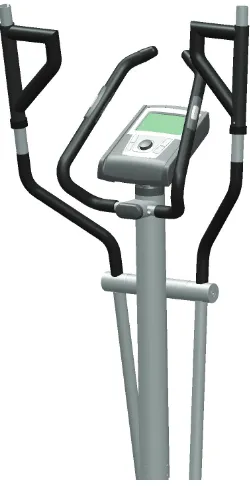
figure 1.1
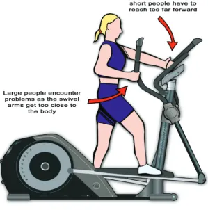
[image:6.595.124.424.43.346.2]Example of a problem with current handlebars
Figure 1.2
Risk of contact when holding the fixed handlebars
figure 1.3
1. Introduc�on
This project was completed as my final assignment to complete my Bachelor phase of the study Industrial Design at the University of Twente. I followed this project at Accell Fitness in Almere, a company that designs and develops fitness devices for the home fitness market. Accell is in charge of two brands: Bremshey and Tunturi.
I was asked to examine the possibili�es of implemen�ng adjustable handlebars in their Tunturi rear-driven crosstrainers.
1.1 Assignment descrip�on/Problem analysis
Accell Fitness is constantly looking for possible improvements for their products. For their current line of the Tunturi crosstrainers, the idea came up to integrate adjustable handlebars to offer the user a more comfortable exercise allowing him/her to set the handlebars at different arm posi�ons. There are also a few problem areas that can possibly be solved by adjustable handlebars. Some of these problems became apparent by customer feedback. In the past, the handlebars were swinging too far for short people. When this was solved by extending the handlebars towards the user, tall people found the handlebars coming too close to the body. Designers at Accell told that it had always been a struggle to design a handlebar that suits tall as well as short people. See figure 1.1.
Another problem became apparent when users held on to the center console; then, the handlebars swung dangerously close alongside the users’ arms (figure 1.2). In that case, adjustable handlebars could be set wide to reduce the risk of contact (figure 1.3). The solu�on shown in the picture was given by Accell and was a possible star�ng point for the project.
In the remaining of this project, some further research is done to inves�gate these problems and probably other problems will become apparent.
Also, at this stage some possible problem areas of the design can already be pointed out. This mainly comprises the sturdiness of the hinge or connec�on point, which should be able to withstand some high torques without any play. Furthermore, the posi�on of the hinge or connec�on point can form a problem, because of the difficulty to suit tall as well as short people.
No�ce that the crosstrainers developed by Accell Fitness are home fitness devices that are sold as a kit and are to be assembled by the user. This should be taken into account during the design process.
Also, some ques�ons were set up to help as a guide line during the rest of the project:
- What is the problem with current crosstrainers?
o How does the posi�on of the handlebars differ from the most ideal posi�on? o How is the user’s training suffering from the non-ideal posi�on of the handlebars?
- How can adjustable handlebars improve crosstrainers?
o How can contact with the user, while holding the fixed handlebars, be prevented by adjustable handlebars?
1.2 Goal
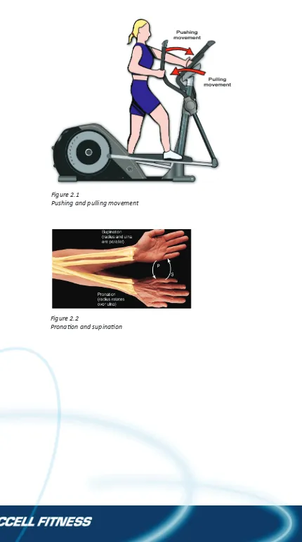
Figure 2.1
Pushing and pulling movement
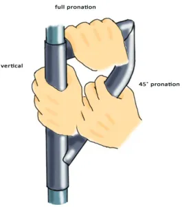
Figure 2.2
[image:10.595.161.418.89.336.2]2. Pre studies
2.1 Ergonomics
Besides the fact that adjustable handlebars allow the user more freedom in se�ng up the posi�on he/she prefers, it should be an even be�er addi�on if it can also be used to train different muscle groups than conven�onally. In order to study this, I applied an analysis of movement of the arm region during a typical crosstrainer exercise. My comple�on of the course ‘anatomy and physiology of movement’ comes in very useful here. No�ce that it is not necessary to use the arms ac�vely during exercise; it is also possible to hold on to the handlebars loosely, relaxing the arm muscles, and even to let go the handlebars completely, using only the legs.
The movement of the arm is accomplished by the muscles around three joints: the wrist, elbow, and shoulder. Ignoring the wrist because of its minor influence on the total force applied, the elbow and shoulder are the joints to focus on. During a typical crosstrainer exercise, the arm movement consists of two steps: a pushing movement and a pulling movement (figure 2.1).
During the pushing movement, extension takes place in the elbow, completely performed by the muscle at the back of the upper arm, the triceps. The forward movement in the shoulder is called ante flexion, mainly caused by the big shoulder muscle, the deltoid muscle, assisted by the biceps and the breast muscle, the pectoralis.
The muscles at the back of the shoulder ini�ate the pulling mo�on, by pulling the upper arm back. Flexion in the elbow is mainly caused by the big upper arm muscle, the biceps. Also, the muscles of the fore-arm play a big part in this movement. So far, the basic movement is discussed.
Next, the consequences of different hand posi�ons have to be examined to determine whether it is useful to apply such a feature on the crosstrainer. In order to do this properly, the difference between prona�on and supina�on has to be explained. Shortly, prona�on is when the palm of the hand faces down; supina�on is when the palm of the hand faces up (figure 2.2).
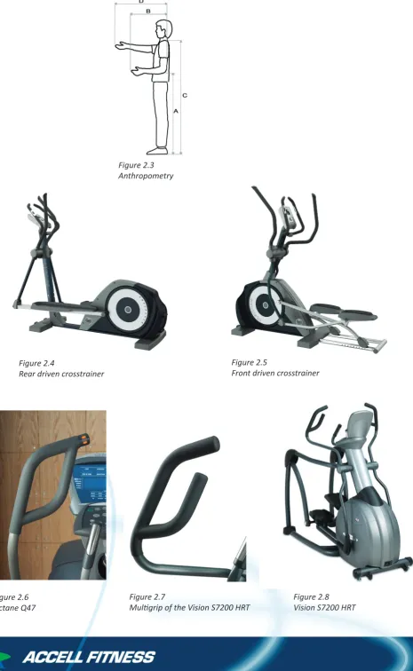
Figure 2.3 Anthropometry
Figure 2.4
Rear driven crosstrainer
Figure 2.5
Front driven crosstrainer
Figure 2.6 Octane Q47
Figure 2.7
Mul�grip of the Vision S7200 HRT
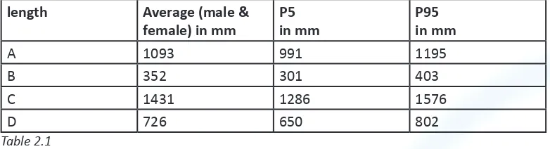
A�er this analysis, it is also useful to have a look at anthropometry, which determines the margins to work with. Again, only the arm region was studied, looking at values that are important for the dimensions of the crosstrainer, like elbow height, shoulder height, and reaching depths. Besides the average dimension for men and women, also P5 and P95 measurements are included (figure 2.3 and table 2.1).
length Average (male & female) in mm
P5 in mm
P95 in mm
A 1093 991 1195
B 352 301 403
C 1431 1286 1576
[image:13.595.113.504.182.288.2]D 726 650 802
Table 2.1
2.2 Compe��on research
Compe��on research is done to get a clear view of where Tunturi stands in the home fitness market and to inves�gate whether the compe��on has already been working in the field of adjustable handlebars.
The Accell Group is in charge of two brands, Bremshey and Tunturi. Both brands have a variety of fitness devices like home trainers, treadmills, spinners and crosstrainers. Bremshey acts mainly in the low and mid segment, being the cheaper, less quality of the two. In contrast, Tunturi is in the top segment, offering top quality for a higher price than Bremshey. All new developments and innova�ons are applied on the Tunturi models to keep up with the compe��on; later on, some of these developments are gradually integrated in the Bremshey models. In the field of crosstrainers in par�cular, there are front driven and rear driven cross trainers. Front driven crosstrainers have the drive wheel en flywheel in front of the user, while a rear driven has them at the back (figures 2.4 and 2.5). This project will focus on the rear driven crosstrainer, the C80 model in par�cular, because of it having the most difficul�es in ge�ng the handlebars right.
Next, some compe��on research was done, mainly looking at the handlebars. Crosstrainers of different brands vary a lot on handlebar design; some have large bends and curvature in it, while others are straighter up. Some have a small center console to hold on to, some a bigger one, and some have none. There are also some models, which had solved the problem of different hand posi�ons with a so-called mul�grip, a top piece of the handlebar that has mul�ple grip posi�ons. Examples are the Octane Q47 (figure 2.6) and the Vision S7200 HRT (figures 2.7 and 2.8).
Figure 2.9
[image:14.595.277.496.287.458.2]Converging movement of the Octane Q47
Figure 2.10
Horizon SXE7.7 with adjustable handlebars
Figure 2.11
Pictures from the user manual of the Horizon SXE7.7
Figure 2.12
Extra handle mounted on the actual handlebars
Figure 2.13
[image:14.595.108.216.291.499.2] [image:14.595.91.520.551.766.2]It was remarkable to find that, except for one model, none of the compe��on had already applied adjustable handlebars on their crosstrainers. That one excep�on is a Horizon crosstrainer, model SXE 7.7, which has an adjustable upper part of the handlebar that can be adjusted to five different angles (figures 2.10 and 2.11). It is pre-assembled; thus, no extra assembly steps for the user. Because this crosstrainer is not for sale in Europe, it could not be tested. Therefore, Accells Salesman in America shared his experiences with the device with us. He is not enthusias�c about it, because the grips are posi�oned at the top of the handlebars, a posi�on few people hold on to normally.
Moreover, small people get pulled too far forward when they posi�on their hands on the adjustable part of the handlebars. In addi�on, when really some torque is put on the unit, the posi�oning of the handlebars seems to move a bit.
A bit of text from the user manual:
Your Horizon SXE7.7 ellip�cal trainer with TARGETtoner™ Handgrips allows you to adjust your handlebar angle to five different posi�ons. This breakthrough innova�on delivers two key benefits: First, for beginners, it allows you to find the handgrip angle that’s most comfortable to you, and will help you get started on your exercise program. Second, as you advance, you can adjust the handgrip posi�on to tone different areas of your arms and shoulders.
To adjust the handgrip posi�ons, simply push in the adjustment bu�on and turn the handle to the desired posi�on.
An extra remark is that some of the salesmen and –women told that they saw no added value in adjustable handlebars, but instead predicted drawbacks like it being another weak spot and a possible extra assembly step for the user. In the remaining of the project, this should be taken very seriously.
2.3 Patent research
Patent research had been done to find out if there are some patents in the area of adjustable handlebars for crosstrainers. Accell had applied for a patent at some extra handles mounted on the handlebars and also for the hinge point shown in the problem analysis. These handles can be rotated to achieve the best possible posi�on for the user. This Patent can be found in appendix B. There are not really any more patents for adjustable handlebars on crosstrainers. There were a lot more on crosstrainers but not par�cularly on adjustable handlebars.
2.4 Current mechanisms
2.5 User tests
In order to determine the ideal posi�on for the hands and arms while exercising on a crosstrainer, two user tests were executed. The exact descrip�on of the tests can be found in appendix A. The results are as follows:
- The risk of contact when holding on to the fixed handlebars has to be avoided. According to this test, this can be achieved by only adjus�ng the handlebars to a wider posi�on.
- Remarkable is the fact that only a few par�cipants used the possibility to adjust the beams inwards or outwards, not even when the possibility to do so was brought moreover to the par�cipants’ a�en�on. Most par�cipants seamed to be pleased with the current width of the handlebars.
- According to the test, the preferred height of the handle should vary from somewhere under 115cm. (which was s�ll too high) to 130 cm. Average preferred handle height during this test was 124,75 cm. However, the average height of the par�cipants was higher than average.
- The average handlebar height of 124,75 cm found here is about 8cm higher than the average handlebar height of 116,88 found in user test 1. This can be
explained by the fact that during test 1 the par�cipants had nothing to hold on to and naturally adopt a running like posi�on, where the arms are held lower and closer to the body. Apparently, according to user test 2, people like to hold the arms higher up when they have something to hold on to. (Test 1 and 2 can in this manner be compared, while the majority of the par�cipants par�cipated in both test 1 and 2.) - In the la�er design process, ver�cal rota�on of the handle does not have to be taken into account. The op�on of ver�cal rota�on was very rarely used in this test; most people liked the handle in the neutral, ver�cal posi�on.
- Like user test 1, most par�cipants preferred the wrist ver�cal and/or 45˚ prona�on. Even so, the op�ons for 45˚ supina�on and full supina�on should held open for the further design process, because it was regularly chosen as an alterna�ve. - The opinions about the free rota�ng possibility for the wrist were divided; some liked it, some not. Thereby, it is not possible to draw a clear conclusion. However, because it is not disliked by all, it is something to be taken into account.
2.6 Conclusions of pre studies
In this paragraph, all the conclusions of the pre studies are put together, from which a design vision and guidelines can be formed.
current handlebar posi�on, which is midway between prona�on and supina�on, is sufficient for endurance training. However, when the user likes to put some power in every now and then, the supina�on/prona�on stances would come in handy.
Compe��on research was done to get a clear view of where Tunturi stands in the home fitness market, where the compe��on stands and whether they are already integra�ng adjustable handlebars in their crosstrainers.
Only one brand, Horizon, has a crosstrainer on the market with adjustable handlebars. Major problems with these adjustable handlebars are the height and strength of it. The adjustable parts are place at the top of the handlebar, making it impossible to use for small people. And when really some torque is put on the unit, the handlebars seem to move a bit.
Furthermore, some brands have introduced a so called mul�grip, a top piece of the handlebar that has mul�ple grip posi�ons. In general, users are very posi�ve about this addi�on; People of different lengths can use it problem free and it brings varia�on in the training. Major drawback is the risk of contact when the user holds on to the fixed handlebars.
In addi�on, one brand has slightly converted the standard back and forth mo�on of the handlebars into a converging movement, similar to a boxing movement. This adapta�on was well received in the market.
Two user tests were executed to obtain informa�on about ideal handlebar posi�on, height and func�on. The first test was done with the arms freely movable to see what the natural movement of the arms is, when not holding on to the handle bars. In the second test, par�cipants used an earlier made prototype with handles that can be adjusted to almost every posi�on. It was useful to see which adjus�ng possibili�es people use and do not use.
Again, it proved that, the risk of contact when holding on to the fixed handlebars has to be avoided. Remarkable is the fact that only a few par�cipants used the possibility to adjust the beams inwards or outwards, not even when the possibility to do so was brought moreover to the par�cipants’ a�en�on. Most par�cipants seamed to be pleased with the current width of the handlebars. Most par�cipants preferred the wrist ver�cal and/or 45˚ prona�on. Even so, the op�ons for 45˚ supina�on and full supina�on should be held open for the further design process, because it was regularly chosen as an alterna�ve. The opinions about the free rota�ng possibility for the wrist were divided; some liked it, some not. Thereby, it is not possible to draw a clear conclusion. However, because it is not disliked by all, it is something take into account. According to the test, the preferred height of the handle should vary from somewhere under 115cm. (which was s�ll too high) to 130 cm. Average preferred handle height during this test was 124,75 cm. However, the average height of the par�cipants was higher than average.
The average handlebar height of 124,75 cm found in test 2 is about 8cm higher than the average handlebar height of 116,88 found in user test 1. This can be explained by the fact that during test 1 the par�cipants had nothing to hold on to and naturally adopt a running like posi�on, where the arms are held lower and closer to the body. Apparently, according to user test 2, people like to hold the arms higher up when they have something to hold on to. (Test 1 and 2 can in this manner be compared, while the majority of the par�cipants par�cipated in both test 1 and 2.)
people liked the handle in the neutral, ver�cal posi�on.
A�er the pre studies, some ques�ons stated in the problem analysis can be answered:
- What is the problem with current crosstrainers?
o How does the posi�on of the handlebars differ from the ideal posi�on? What can be said is that there is no ideal posi�on. Users are
individually too different to come up with one handlebar that suits all. People some�mes like to adopt a different angle of the wrist in comparison with the posi�on on current crosstrainers.
o How is the user’s training suffering from the non-ideal posi�on of the handlebars?
In the past, the handlebars were swinging too far for short people. When this was solved by extending the handlebars towards the user, long people found the handlebars coming too close to the body. The current posi�on of the hand does not allow the user to apply maximum force. Maximum force can be obtained by a prona�on or supina�on stance. However, this is not probably not o�en required, since training on a crosstrainer is in general an endurance training. The tests showed that some people liked a free wrist rota�on during the back and forth movement.
- How can adjustable handlebars improve crosstrainers?
o What are possible solu�ons for integra�ng adjustable handlebars? This will be looked at during concept stage
o Which posi�ons are best for a par�cular crosstrainer exercise?
Height of the handlebar (the part the user grabs): between 105 and 140 cm.
Should allow at least four wrist angles: 45˚ prona�on, ver�cal, 45˚ supina�on and full supina�on.
Width of the handlebars of around 60 cm. There were no indica�ons that the handlebars should be adjustable in width.
Free rota�on of the wrist can be an op�on.
o How can contact with the user, while holding the fixed handlebars, be prevented by adjustable handlebars?
The op�on tested in user test 2, in which the handlebars could be set wide, worked fine.
The best solu�on is to remove the upper part of the handlebars.
2.7 Design vision
Here, the main points for genera�ng concepts will be listed and a vision of the final product will be described.
Important design points:
Requirements Remarks
P5 – P95 people must be able to use the handlebars problem free
Adjus�ng the handlebars must be able without the help of tools.
Adjus�ng must be performed by max. 1 person.
The hinge point must be sturdy enough to withstand….
The hinge point may not need an extra assembly step by the user
Pre assembly Adjus�ng the part must be done easily with
no extra effort
Current Accell prototype takes too much effort
Height of the handlebar (the part the user grabs) must be between 105 and 140 cm.
Probably height adjustment The handlebar should allow at least four wrist
angles: 45˚ prona�on, ver�cal, 45˚ supina�on and full supina�on.
Width of the handlebars must be around 60 cm.
There must not be any play in the part Produc�on of the product must be done with standard parts en techniques.
no machined parts The new part must be produced as cheap as
possible
The part the user holds on to must always be covered with foam rubber
When moving, the new part may not come closer than 25 mm. to sta�onary parts of the crosstrainer
The new part will be introduced on Accell’s top model crosstrainer and should therefore be of high quality and should match the look of the machine
The new part may not produce any sound or noise
The crosstrainer, including the new part, must fit in the current shipping boxes for transport
Aspira�ons
Adding a converging, boxing like movement Adjus�ng the part must be performed with max. one hand.
The possibility of free rota�on of the wrist The new part must be produced with no extra produc�on costs.
Table 2.2
body of tall people.
- Some supina�on and prona�on possibili�es in the wrist are wished to give the user the ability to apply more force when he or she wants so. For others, it can contribute to a more comfortable training.
- Possible free rota�on of the wrist
- A converging, boxing movement could improve crosstrainer exercise.
- The risk of contact when the user holds on to the fixed handlebars should be avoided.
Dimensions:
- Height of the handlebar (the part the user grabs): between 105 and 140 cm. - The handlebar should allow at least four wrist angles: 45˚ prona�on, ver�cal,
45˚ supina�on and full supina�on. - Width of the handlebars: around 60 cm.
Possibili�es for the design
- The new design can be an adjustable part that is fixed to the exis�ng handlebars. Adjus�ng the part should be performed with no more than one hand
- A mul�grip can partly solve de problem of the prona�on/supina�on grip op�ons. A height adjus�ng can be added to it to fit small as well as tall people. - It can also be an extra unit that is mounted on/over the handlebars and has
mul�ple adjus�ng possibili�es for the users in order to get the preferred grip. The user can be given the possibility to remove the part and just hold on to the conven�onal handlebars, if its shape is not adjusted.
- In order too keep the costs low, a low tech op�on can also be thought of. Risk of that is that it not sa�sfies the user’s wishes.
2.8 List of requirements
Figures 3.1 and 3.2
[image:24.595.112.237.90.334.2]Concept 1. A mul�grip adjustable in height
Figure 3.3
Working principle of concept 1 Figure 3.4Mul�grip with the track visible
Figure 3.5
3. Concepts
3.1 Idea phase
Then, three main direc�ons were pointed out. First, there is the mul�grip, which is a unit somewhere on the handlebar with mul�ple posi�ons to hold on to like previously found at the compe��on research. Second, some solu�ons for the problem of the difference between individuals were generated. As previously pointed out, it proves to be very difficult to design a handlebar that suits individuals of all sizes. Ideally, the handlebar is freely moveable in a 3D space, but can s�ll be secured in a certain posi�on. The third concept is a concept which can be adjusted le� to right with a simple movement of the hand.
3.2 Concept Phase
3.2.1 Concept 1
This concept consists of a so called mul�grip that can be adjusted in height (figure 3.1 and 3.2). A mul�grip is a unit a�ached to the handlebars that has mul�ple grip op�ons for the user to hold on to. An example of a mul�grip can be found on the Q47 model of Octane fitness, see also 2.2 Compe��on Research.
In user test 2, it was found that there was a lot of difference in the preferred height of the handles. That is why a height adjustment system is integrated in the mul�grip.
Working principle
Adjus�ng the height of the mul�grip is realized with a clamping mechanism. The lower end of the mul�grip tube contains a screw thread on which a grip with an inner screw thread can rotate and thereby move up and down. As it moves up, it compresses a rubber ring, which thereby pushes against the inner tube (handlebar, swing arm) and clamps itself onto the inner tube. The mul�grip contains a pen which slides in a ver�cal track of the inner tube to prevent rota�on around the inner tube. (figures 3.3 and 3.4)
Design mul�grip
There are a lot of different shapes possible for the mul�grip. Curvature and diagonals can be used to achieve as many grip angles as possible. The most important grip angles are 45˚ prona�on and ver�cal. (figure 3.5)
These designs meet the requirement of 45˚ prona�on and ver�cal; the second also makes 45˚ supina�on possible and nr. 4 contains all five grip op�ons. For now however, the first design will be used, because it is be�er producible and stronger as it is a closed shape with no open ends.
Ergonomics
Figure 3.6
The mul�grip clamps by rota�ng a grip down. This will not easily come loose during exercise, while this twis�ng mo�on does not occur during training.
This clamp mechanism is fla�er and be�er integrated in the shape of the mul�grip than a clamp knob would, and can thereby also be grabbed during training.
Materials / produc�on method
The inner tube is a steel tube with an outer diameter of 30 mm and thickness of 1,5 mm.
The mul�grip part consists of three steel tube parts welded together. The main tube (which slides over the inner tube) has an outer diameter of 36 mm with a thickness of 2,5 mm. This piece needs extra tooling for the screw thread. The two other pieces have a thickness of 1,5 mm.
The mul�grip is dipped in a bath with a rubberlike coa�ng for extra grip. Thread and opening holes up and down should be covered to leave them untouched. A typical coa�ng is 3 mm thick, which increases the total width of the tube with 6mm. The clamp part will be injec�on mould of polycarbonate. This requires a mould and perhaps some tooling a�erwards to remove irregulari�es.
The rubber ring will be a purchase part.
Problems
– Risk of play in the mechanism that prevents rota�on. The pen must fit very �ght in its guide track
– High risk of wear of the rubber ring by twis�ng from above.
– High risk of wear of the plas�c grip part, screwing on metal parts: Grip/clamp part can also be made of steel, but needs lots of tooling if so.
– Current handlebar thickness/width has to be reduced.
– No foam on inner tube / swing arm: paint instead can be a solu�on but that will be scraped off as the mul�grip is sled up and down.
– Weld line of outer tube can cause trouble when sliding over the inner tube. – – Possible that it requires extra tooling.
– The screw thread end tube ends needs to be covered for the dip bath for the coa�ng.
– The swing arms need some unusual curvature to create space for the mul�grips.
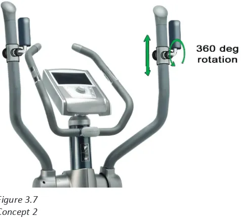
Figure 3.7 Concept 2
Figure 3.8
3.2.2 Concept 2
This concept is based on the prototype used in user test 2. The prototype is further explained in Current Mechanisms. This prototype consists of a handle-unit that is adjustable in height along the handlebar. The handle itself can be rotated along its square axle to adjust the preferred wrist angle. In the user tests was found that people like several different wrist angles, especially ver�cal and 45˚ prona�on. The handle of this concept can rotate a full 360˚ and can be fixed at any angle. (Figure 3.7)
Working principle
The handle is connected to the handlebar with a piece of tube that fits around the handlebar. This is height adjustable with a pulling knob at the back, just as Accell already applies on the home trainers for saddle height adjustment. This type of height adjustment requires a set of holes at the back of the handle bar along a ver�cal path for the pin of the pull knob to lock into.
It is also possible to integrate the height adjustment of concept 1 in this concept, and it might even work be�er here, because no torque is applied on the handle around the handlebar, such as at concept 1.
To fix the angle of the handle, the user can screw a ring along a screw thread which clips on to the metal piece of the height adjustment unit. This ring can also be le� loose, which gives the possibility to rotate the handle freely during training. (figure 3.8)
Design
This is esthe�cally probably not the best concept, but when this concept is chosen, some further form studies, especially on the handle itself, can be done to improve the looks and match it to the rest of the crosstrainer.
Ergonomics
The handle can be set in any angle, which sa�sfies every user if it comes to wrist angle. So, also users with different preferences than the average user will be sa�sfied with this concept. Furthermore, in user test 2, it was not very clear whether people liked a freely rota�ng handle or not. In this concept the handle can be fixed or rotate freely and should therefore also sa�sfy every user. The height adjustment allows small as well as tall people to use the handles problem free. As shown in user test 2, the ver�cal rota�on of the handle is of no value and is thereby not integrated.
Materials / produc�on method
The handle itself is a steel tube with a diameter of 36 mm. and a foam rubber tube of 3 mm. thick, sled over it; total width of 42mm.
This tube is welded in a pre-bent bracket of 3mm. thick steel with a width of 20 mm. in the middle and 42 at the weld points. 36 mm. holes are drilled for the tube to fit in. A 30mm pen with a diameter of 10mm will be machined to give it a screw thread along 20 mm from one side.
Figure 3.9 Concept 3
Next, a metal bush with a diameter of 30mm and thickness of 5 mm is equipped with a bearing and a lock ring.
The pen is inserted in the bearing and also locked with a lock ring.
Now the handle can be welded onto the outer tube for the height adjustment.
On the other side of the tube, a steel bush with an inner screw thread is welded on for the pull knob for height adjustment.
As the holes for the height adjustment are drilled on the handlebar, the en�re handle can slide on.
Problems
- High tooling/assembly costs - Needs to be pre-assembled
- Pain�ng the handle can cause problems, while the foam rubber and the screw threads must remain unpainted
- During exercise, the bearing is loaded in a lateral direc�on, which it is not designed for.
- Does the clamp mechanism work properly? Can rota�on of the handle unscrew the clamp ring? Can the bearing be pulled to pieces by the screw thread?
- The bigger the clamp ring, the more power can be applied. - Risk of pinching the skin between the clamp ring and steel bush - The height can not be adjusted while the user is on the crosstrainer. - Handlebar requires some unusual curvature.
3.2.3 Concept 3
This concept direc�on was chosen because it was the original idea from Accell. (figure 1.3)
This concept makes it possible to set the handlebars in three different widths as shown above. From user test 2, however, this adjustment possibility is not actually needed and seems redundant. On the other side, the number of par�cipants in user test 2 was not high enough to completely follow its conclusions, they are more like guidelines. In addi�on, this concept sa�sfies the wish of the user to set the handlebars wide to be able to use the fixed handlebars problem free (figure 3.9). In that context, this concept can be equipped with a mul�grip unit.
Working principle
On the handlebar, the foam rubber is interrupted for approximately 5 cm. On this part, a plas�c grip is a�ached which can be rotated. On the inside, this grip has a li�le pin that slides in a milled, horizontal path of the handlebar. To this pin, a steel wire is a�ached that runs down via a hole in a horizontally mounted bracket. This causes the wire to be pulled upwards as the grip rotates.
steel tube welded square on the lower part of the handlebar. As the grip is rotated and the wire pulled up, so does the rod, and the upper part of the handlebar can be rotated into three (or otherwise, depending on the number of holes drilled) different posi�ons. (figure 3.10)
Design
In this concept, the locking mechanism has been very nicely integrated in the
handlebar. The rota�ng grip has the same width as the rest of the handlebar and can thereby be easily hold on to during exercise. The hinge point is in design similar to the hinge point lower down, around which the whole handlebar rotates.
Ergonomics
The user can adjust the width of the handlebar from approximately 50 cm. to 70 cm. to his/her own liking. The handlebars can also be set wide to make use of the fixed handlebars be�er possible.
Furthermore, when the handlebars are adjusted inwards or outwards, a slight prona�on and supina�on is created.
Since there are no extra handles to hold on to, no height has to be adjusted. Instead the curvature has to be right to suit small as well as tall people.
Materials/produc�on
First, the lower part of the upper tube is equipped with the bracket with rod. This is pre-assembled and spot welded into place. It consists of a circular plate with a square hole milled in. In this hole the bracket with rod is placed. This bracket is welded to a li�le axle, which is held in place by two li�le clamps mounted on the circular plate. All of its parts are made of steel.
A piece of tube of 42 mm long and the same width is cut in half and a hole for the rod to fit in is drilled. The tube is welded into place. This can later be sled over the lower part, which has a piece of steel tube of 42 mm long and 38mm width and three holes welded square onto it. Two plas�c covers cover the tube ends.
The upper part of the handlebar will be machined to give it a milled path along which the pin of the plas�c grip slides. Also the bracket with hole, which is punched, is being spot welded into place. Then, the plas�c grip, which is injec�on mould, is a�ached and the steel wire is a�ached to it. The upper tube is finished with a plas�c part that fits on top.
Problems
- There may not be any play in the rod/hole connec�on.
- Is the plas�c pin strong enough to withstand high forces when someone is pu�ng a lot of force on the grip.
- The locking mechanism may not unlock during exercise; therefore the system must be in the opposite direc�on of each other, rota�ng outwards. (inwards is a more natural movement, but will cause the system to unlock).
- A�achment of the spring?
Requirements Remarks C.1 C.2 C.3
P5 – P95 people must be able to use the handlebars problem free
4 4 2
Adjus�ng the handlebars must be able without the help of tools.
5 4 5
Adjus�ng must be performed by max. 1 person. 5 4 5 The hinge point must be sturdy enough to
withstand….
4 3 2
The hinge point may not need an extra assembly step by the user
Pre assembly 3 3 4 Adjus�ng the part must be done easily with no
extra effort
Current Accell prototype takes too much effort
4 3 4
Height of the handlebar (the part the user grabs) must be between 105 and 140 cm.
Probably height adjustment 5 4 2 The handlebar should allow at least four wrist
angles: 45˚ prona�on, ver�cal, 45˚ supina�on and full supina�on.
4 5 2
Width of the handlebars must be around 60 cm. 4 5 4 There must not be any play in the part 2 2 2 Produc�on of the product must be done with
standard parts en techniques.
no machined parts 3 3 3 The new part must be produced as cheap as
possible
4 3 3
The part the user holds on to must always be covered with foam rubber
5 5 4
When moving, the new part may not come closer than 25 mm. to sta�onary parts of the crosstrainer
5 4 2
The new part will be introduced on Accell’s top model crosstrainer and should therefore be of high quality and should match the look of the machine
5 2 3
The new part may not produce any sound or noise
4 4 4
The crosstrainer, including the new part, must fit in the current shipping boxes for transport
5 5 5
Aspira�ons
Adding a converging, boxing like movement 4 4 2 Adjus�ng the part must be performed with
max. one hand.
3 2 5
The possibility of free rota�on of the wrist 1 5 1 The new part must be produced with no extra
produc�on costs.
1 1 1
[image:34.595.75.528.69.842.2]Total 80 75 65
Table 3.1
3.3 Chosen Concept
When all three concepts are worked out to a certain point, it is �me to chose one of the concepts to work out to a final product.
3.3.1 Assessment list of requirements
First, in order to get a clear view of how well the three concepts sa�sfy the requirements and aspira�ons set up in the list of requirements, the concepts are balanced with the list of requirements. For each requirement, each concept was rated to indicate how well each concept sa�sfies that par�cular requirement. The rates vary from 1 to 5 were 1 is the worst and 5 the best possible score. Then, the scores are added up to achieve a total score for each concept a�er which can be seen which concept sa�sfies the list of requirements the best. (Table 3.1)
Concept 1 was rated the best with a score of 80 out of a possible 105. It scores
par�cularly well on prac�cal aspects. With this assessment in mind, I personally would go for concept 1, also. When this concept is worked out to eventually a prototype, it is interes�ng to see whether the height adjustment will actually func�on in prac�ce. Also, I think that the looks of concept 1 match the crosstrainer the best. That is the main reason why I would not choose concept 2. Concept 3 does not sa�sfy the wishes of the user concerning ergonomics; and seems the less ideal op�on.
3.3.2 Final verdict
Next, a videoconference mee�ng was arranged with Henri Kuivala, the chief project management and Larri Fonsen of the department of Research & Development of Accell Fitness in Finland. A�er a presenta�on in which the pre studies and concepts are explained, they gave their opinion and eventually the final idea to work out into a concept. By mutual agreement, Concept 1 was chosen to work out, but without the height adjustment. All the adjus�ng systems were found a too high risk to implement. That mainly comprises the risk of failure of the system and the extra costs it will contain. Also the quality of the adjus�ng systems on the long term could not be guaranteed.
However, the mul�grip was found a good idea, and with the right design, the problem of the required height differences can probably be solved. The next stage will comprise finding the ideal shape, both on ergonomics and looks, to work out as a prototype for user tests. In the remaining of the report, Concept 1 is called Mul�grip.
Requirements Remarks C.1 C.2 C.3
P5 – P95 people must be able to use the handlebars problem free
4 4 2
Adjus�ng the handlebars must be able without the help of tools.
5 4 5
Adjus�ng must be performed by max. 1 person. 5 4 5 The hinge point must be sturdy enough to
withstand….
4 3 2
The hinge point may not need an extra assembly step by the user
Pre assembly 3 3 4 Adjus�ng the part must be done easily with no
extra effort
Current Accell prototype takes too much effort
4 3 4
Height of the handlebar (the part the user grabs) must be between 105 and 140 cm.
Probably height adjustment 5 4 2 The handlebar should allow at least four wrist
angles: 45˚ prona�on, ver�cal, 45˚ supina�on and full supina�on.
4 5 2
Width of the handlebars must be around 60 cm. 4 5 4 There must not be any play in the part 2 2 2 Produc�on of the product must be done with
standard parts en techniques.
no machined parts 3 3 3 The new part must be produced as cheap as
possible
4 3 3
The part the user holds on to must always be covered with foam rubber
5 5 4
When moving, the new part may not come closer than 25 mm. to sta�onary parts of the crosstrainer
5 4 2
The new part will be introduced on Accell’s top model crosstrainer and should therefore be of high quality and should match the look of the machine
5 2 3
The new part may not produce any sound or noise
4 4 4
The crosstrainer, including the new part, must fit in the current shipping boxes for transport
5 5 5
Aspira�ons
Adding a converging, boxing like movement 4 4 2 Adjus�ng the part must be performed with
max. one hand.
3 2 5
The possibility of free rota�on of the wrist 1 5 1 The new part must be produced with no extra
produc�on costs.
1 1 1
Figure 4.1
[image:36.595.45.538.385.826.2]Three views of the conven�onal handlebars
Figure 4.2
Three views of mul�grip 1
Figure 4.3
Three views of mul�grip 2
Figure 4.4
4. Mul�grip
4.1 Finding right shape
When the concept of the mul�grip was chosen, it is �me to find the ideal design of the mul�grip, both on Ergonomics and looks. Some design studies were done, with the results of the pre studies and user tests in mind. The results of the design studies and an explana�on are shown below; of every mul�grip, the pluses en minuses are pointed out. Note that integra�ng a mul�grip will influence the design of the fixed handlebars. A mul�grip would make contact with the conven�onal fixed handlebars.
First, to get a clear view of the actual differences the mul�grip offers, some pictures of the conven�onal handlebars (figure 4.1).
Mul�grip 1 (figure 4.2)
Pluses:
- Almost all desired grip op�ons; only supina�on is missing. - Wide grip op�ons for broad people, narrower for slim people.
- For tall users, the broader grip op�ons are further forward (longer arms); for small users the inner grip op�ons are located somewhat closer to the user.
- The lower part of the grip, for real small users, is more ver�cal (seen from the side in the posi�on closest to the user) to avoid stress on the user’s wrist.
Minuses:
- The lower part of the grip, for real small users, maybe somewhat too wide. - Concerning the ver�cal parts of the mul�grip; the wide ver�cal parts (presumably mostly used by tall people) are somewhat lower placed than the inner ver�cal parts, which are presumably mostly used by smaller people.
- The looks of this mul�grip do not en�rely match and complement the en�re design of the crosstrainer.
Mul�grip 2 (figure 4.3)
Pluses:
- Number of different grip op�ons; especially the upper outer part offers the user a lot of grip op�ons.
- Wide grip op�ons for broad people, narrower for slim people.
- The design of the mul�grip matches the design of the en�re crosstrainer. Minuses:
- The lower part of the grip, for real small users, maybe somewhat too wide. - The outer parts are placed more towards the user than the inner parts. - Maybe the curvature in the upper outer part feels awkward to some users. - Only full prona�on for small users.
Mul�grip 3 (figure 4.4)
Pluses:
Figure 4.5
[image:38.595.83.504.308.814.2]Two views of mul�grip 4
Figure 4.6
Two views of mul�grip 5
Figure 4.7
Minuses:
- The design of the mul�grip not really suits the crosstrainer. - No supina�on
- No prona�on for ‘the average’ person
- The wider ver�cal grip is placed lower than the inner ver�cal grip.
Mul�grip 4 (figure 4.5)
Pluses:
- A lot of grip op�ons; prona�on for small, tall, slim and broad people. Also supina�on is available. Horizontal grip only for tall people.
Minuses:
- Top piece maybe too narrow in rela�on to the other top piece.
- Radius of the curved part maybe too small, causing possible problems when users hold on to there.
- It is a daring design, which probably does not suit the crosstrainer.
- Sharp angle in the top of the mul�grip can feel �ght when users hold on there.
Mul�grip 5 (figure 4.6)
Pluses:
- Simple, triangular shape with most grip op�ons.
Minuses:
- Angular shape does not really match the design of the crosstrainer. - For different shapes of persons there is not much choice of grips. - Horizontal grip only on top; no prona�on for tall people.
Fixed handlebars
Two different designs for the new fixed handlebars have been made. In the pictures above, these designs can already be dis�nguished. For the sake of completeness, some pictures of the two designs (figures 4.7 and 4.8).
Fixed handlebar 1 is designed to give the users two upright handles to hold on to, similar to the conven�onal handlebars. However, this fixed handlebar is quite a bit shorter and somewhat narrower to avoid contact with the mul�grips. Fixed handlebar 2 is more like a small steer and should be a natural feeling shape for users to hold on to.
4.2 Final design
Another mee�ng has been arranged to decide which of the previously shown five mul�grips will be worked out to a prototype. Eventually, mul�grip 2 has been chosen, because its shape matches the design of the crosstrainer and offers a nice range of grips. The few drawbacks it has can easily be overcome with some adjustments (figure 4.9):
Figure 4.9
Area’s that need improvement
[image:40.595.83.523.354.545.2]The numbered spots are explained in the text
Figure 4.10
2. The horizontal part of the mul�grip will be given an angle to obtain a more prona�on grip.
3. The part where the handlebar is fixed to the hinge point needs to be straight for about 7 cen�meters to be able to fit the plas�c hinge point covers.
4. The lower part of the grip (the part under the mul�grip), for real small users, needs to be more ver�cal (seen from the side in the posi�on closest to the user) to avoid stress on the user’s wrist.
5. The outer parts have to be placed somewhat further away from the user, for taller, broader people.
Figure 5.1
Photographs of the prototype
Figure 5.2
[image:42.595.64.535.507.831.2]5. Prototype & tes�ng
5.1 Prototype
When the final design of the mul�grip was finished, the prototype stage started. The main purpose of this prototype is to execute user tests with it, mainly focusing on ergonomics and comfort, but also the looks of the design will be assessed. Therefore, not only the shape of the handlebars was important, but also the finishing touch was paid a�en�on to. Due to lack of �me and due to the a�en�on that was necessary to get the handlebars in the right shape, there was no �me le� to construct the fixed handlebars also. Unfortunately, the fixed handlebars can thereby not be tested during the user tests.
Each handlebar consists of two tubular parts with a diameter of 27 mm and a thickness of 2,5 mm which were bent in the right shape and welded in place. The handlebars were then mounted on an older C60 model crosstrainer, which does not differ in geometry from a C80 model. As a grip, which in the final product will be a dipped coa�ng, a ribbon used on the steer of race bikes was used (figure 5.1). During the construc�on of the prototype, the mul�grip part was bent forward by 11˚, an adjustment that was not yet applied in the SolidWorks model. In the series of pictures on the le� (figure 5.2), it can be seen that the original handlebars has its upper part leans somewhat more forward than the new mul�grip. To avoid the risk of the mul�grip ge�ng too close to the body, the mul�grip part of the prototype was bent forward.
5.2 Tes�ng
With this prototype, an extensive user test has been executed. According to this user test some design recommenda�ons are stated. User test 3 is the final test of this project. Here, the final prototype of the mul�grip concept is tested to find the strengths and weaknesses and to make clear which aspects of the concept need to be improved. Eventually, the test results are used to evaluate whether this design sa�sfies the clients’ whishes enough or whether a redesign is needed.
5.2.1. Test set-up
Figure 5.5
Redesign that has to be made according to user test 3 Figure 5.3
Most popular grips by the total group of par�cipants
Figure 5.4
[image:44.595.76.217.109.331.2]5.2.2. Test results
In general, par�cipants were posi�ve about the new mul�grip design. Every par�cipant was able to find a comfortable posi�on for him-/herself. The looks were also
appreciated. The pictures on the le� page show which grips were most popular among the par�cipants. Figure 5.3 shows the percentages by which a certain grip was chosen by the total group op par�cipants. Figure 5.4 shows the percentages by which a certain grip was chosen by the small and tall par�cipants.
Although the overall opinion was posi�ve, some small people found the part under the actual mul�grip (grip 5 in the user test) s�ll leaning backwards too far, although it had already been changed in comparison to the conven�onal handlebars. The lower part of the mul�grip should be extended more towards the user, so that the part leans backwards more, according to the red line shown le� (figure 5.5).
Figure 6.1
6. Conclusion
6.1 Result
According to the results from user test 3, this mul�grip design has the poten�al to be integrated in the Tunturi C80 model. All par�cipants were able to find a comfort-able posi�on on the mul�grip. On the pages on the le� (figure 6.1), some pictures are shown of the final model, so with the li�le adjustment according to user test 3 inte-grated.
As a conclusion, it can be said that a sa�sfying result has been realized. The project started off with some thorough research, followed by an extensive design process of concept finding, adjus�ng, prototyping, and tes�ng. When the final result is compared with the goal set at the beginning of the project, it is clear that the concept of manu-ally adjustable handlebars was put aside. However, that was done with legi�mate reasons thanks to thorough research and tes�ng, which made clear that adjustable handlebars were most likely not the best op�on to solve the problem. The final mul-�grip offers the users enough grip op�ons and freedom of movement and is easier to produce with a smaller chance of failure.
However, the goal that the final design has to discern itself from compe�tors is not really accomplished. The idea of a mul�grip was already present at a few crosstrainers on the market, although the shape differs slightly among one another.
6.2 Recommenda�ons
Although the result can be called sa�sfying, there are s�ll some recommenda�ons for the con�nua�on of implemen�ng the mul�grip in the product range. First of all, some test should be done with the new design of the fixed handlebars. Although the new design does not reach too far forward and allow the user an upright posi�on, the risk of contact of the mul�grip with the user can not be ruled out yet.