1 Department of Chemistry, University of Oxford, Oxford OX1 3TA, UK. 2 School of Physics & Astronomy, University of
Nottingham, Nottingham, NG7 2RD, UK. *e-mail: harry.anderson@chem.ox.ac.uk, peter.beton@nottingham.ac.uk
Supramolecular nesting of cyclic polymers
Dmitry V. Kondratuk,
1Luís M. A. Perdigão,
2Ayad M. S. Esmail,
2James N. O’Shea,
2Peter H. Beton
2* and Harry L. Anderson
1*
Monodisperse cyclic porphyrin polymers, with diameters of up to 21 nm (750 C-C bonds), have been prepared using Vernier template-directed synthesis. The ratio of the intrinsic viscosities for cyclic and linear topologies is 0.72, indicating that these polymers behave as almost ideal flexible chains in solution. When deposited on gold surfaces, the cyclic polymers display a new mode of two-dimensional supramolecular organisation, combining encapsulation and nesting: one nanoring adopts a near-circular conformation thus allowing a second nanoring to be captured within its perimeter, in a tightly folded conformation. Scanning tunnelling microscopy reveals that nesting occurs in combination with stacking when nanorings are deposited under vacuum, whereas when they are deposited directly from solution under ambient conditions, there is stacking or nesting, but not a combination of both.
The tertiary structures of biological macromolecules are achieved through folding, coiling and multiplex formation, driven by the cooperative effect of many weak interactions1. Synthetic monodisperse macromolecules with similar cooperative folding behaviour provide a viable approach to the programmed fabrication of 3D nanostructures2-5. Here we show that cyclic porphyrin polymers, with molecular weights of 30–60 kDa, self-assemble into nested structures on a gold surface. These nested assemblies are only observed when the cyclic polymer has 30 or more repeat units, in keeping with the predictions of a simple geometrical model.
The importance of non-covalent self-assembly in biology has inspired many studies of supramolecular organisation on surfaces6-8, generating 2D assemblies with progressively escalating complexity, from early work on simple structures such as clusters9 and rows10,11, to nanoporous arrays12,13, host-guest architectures14-16, hierarchical arrangements17, and multicomponent assemblies17-19. However, cooperative conformational control has proved difficult to achieve, and this remains a significant gulf between artificial and biological systems. One reason for this difference is that biological macromolecules are much more flexible than the component molecules studied in 2D supramolecular assemblies which are small and, with some exceptions20,21, are often treated as quasi-rigid building blocks. Here we illustrate how interactions between large flexible molecules can result in biomimetic cooperative conformational organisation.
Studies of linear and cyclic butadiyne-linked zinc porphyrin oligomers (structures l-PNTHS and c-PN, Fig.
1) have shown that the distance between the centres of the porphyrin units along the chain is a = 1.35 nm5,22,23. Thus the contour length of a linear oligomer, or the perimeter of a nanoring, is Na, where N is the number of porphyrin repeat units. Previously we have shown that nanorings adsorbed on Au(111) exhibit flexibility24-26, and also that they can act as nanoscale traps for other adsorbed species, such as C60 guest molecules27. However, in order for one nanoring to be adsorbed
inside another, the dimensions of the nanoring must exceed a critical threshold. The footprint area of a nanoring is simply Nad, where d is the effective width of the chains (ca. 2.1 nm; see below). Note that this area is independent of conformation. The maximum area enclosed within the ring, and available for trapping a second nanoring, is π(Na/2π – d/2)2. In order for self-trapping to occur, equation (1) must be satisfied,
π(Na/2π – d/2)2> Nad (1) which implies that the nanoring needs to consist of more than 29 porphyrin units (N≥ 29).
The largest ring that we have synthesised previously is c-P24 (N = 24)5. Here we describe how Vernier template-directed synthesis can be extended to prepare rings of up to 50 porphyrin units, and we show, using scanning tunnelling microscopy (STM), that rings with N ≥ 30 support a nested packing in which one nanoring is trapped in a compact conformation inside a second nanoring.
2
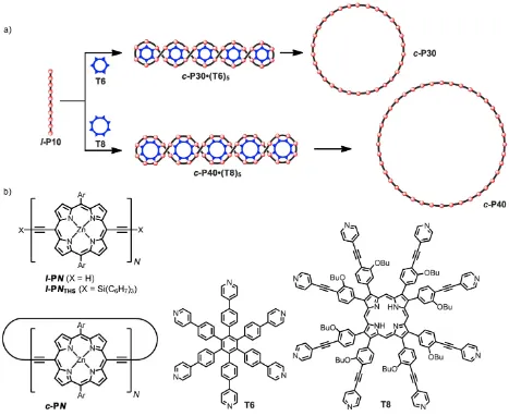
Figure 1. (a) Templated synthesis of the nanorings c-P30 and c-P40. Reagents: i) PdCl2(PPh3)2, CuI, benzoquinone, i-Pr2NH; ii)
pyridine; (b) Structures of l-PN, l-PNTHS,c-PN, T6 and T8; Ar = 3,5-bis(octyloxy)phenyl.
Results and discussion
Synthesis. We investigated the palladium-catalysed oxidative coupling of the linear zinc-porphyrin 10-mer l-P10 in the presence of hexa-pyridyl template T623,34 and octa-pyridyl template T835 (Fig. 1). These reactions are expected to generate the nanoring-template complexes c-P30•(T6)5 and c-P40•(T8)5,respectively, as mixtures of
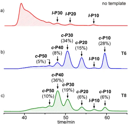
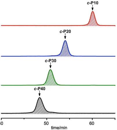
stereoisomers; the templates were displaced from the nanorings by addition of pyridine, prior to analysis and purification. Crude reaction mixtures were analysed by GPC and compared with the distribution of products from coupling under identical conditions in the absence of a template (Fig. 2). When no template is present, all the products are linear polymers; traces of linear oligomers l-P10, l-P20 and l-P30 can be detected but there is no evidence of cyclic products (Fig. 2a).
Coupling of l-P10 in the presence of T6 gives the expected cyclic porphyrin 30-mer c-P30 as the main product (34% analytical yield, 26% isolated yield), however other by-products such as c-P10, c-P20, c-P40 and c-P50 are also formed (Fig. 2b). The reaction was tested using a range of l-P10 / T6 ratios and the yield of c-P30 was found to be highest (34% analytical yield) for a l-P10 / T6 ratio of 3/5. Reducing the amount of template
below this stoichiometry increases the ratio of c-P30 / c-P10, but reduces the yield of c-P30 due to increased formation of linear polymers. Increasing the amount of template above 5/3 equivalents reduces the ratio c-P30 / c-P10 and reduces the yield of c-P30.
Changing the template to T8 shifts the product-distribution to make c-P40 predominate (36% analytical yield, 27% isolated yield), as expected from the Vernier principle (Fig. 2c). The yield of c-P40 was found to be greatest for a l-P10 / T8 ratio of 1:1 (36% analytical yield). Reducing the amount of template below this stoichiometry increases the ratio of c-P40 / c-P10, but reduces the yield of c-P40 due to increased formation of linear polymers. Increasing the amount of template above 1 equivalent, reduces the ratio c-P40 / c-P10 and reduces the yield of c-P40.
[image:2.595.64.531.58.440.2]3
Figure 2. Analytical GPC traces (toluene/1% pyridine, detection at 500 nm) of the crude reaction mixtures from coupling l-P10 (a) in the absence of a template, (b) in the presence of T6, and (c) in the presence of T8. The catalysts and 1,4-benzoquinone were removed by passing the sample through a short GPC column in CHCl3/10% pyridine as eluent. The analytical yields
were determined by comparison of resolved peaks in the corresponding recycling GPC traces (see Supplementary Information).
Gel Permeation Chromatography. All the isolated nanorings gave sharp single-component GPC profiles. The elution times confirm the molecular weights, when calibrated with data from previously characterised nanorings (c-P6, c-P8, c-P12, c-P16, c-P18 and c-P24), as shown from the plot of log molecular weight, logM, vs.
elution time t in Fig. 3. The points for linear and cyclic oligomers define two parallel straight lines, reflecting the more compact conformations of the cyclic oligomers. For molecular weights in the linear range for a GPC column, the elution time t is related to the molecular hydrodynamic volume Vh by equation 236,
log Vh = a – bt (2) where a and b are constants characteristic to the column. The hydrodynamic volume is related to the molecular weight M and the intrinsic viscosity [η] by equation 3
(where K is a constant)37.
Vh = KM[η] (3)
Combining equations 2 and 3 gives:
logM = a' – bt (4)
where a' = (a – logK – log[η]). In Fig. 3, the data for
cyclic and linear oligomers are fitted to two parallel straight lines, according to equation 4, giving a'cyclic = 7.213 ± 0.003, a'linear = 7.073 ± 0.003 and b = 0.053 ± 0.001 min–1. If we assume that K is independent of the linear or cyclic topology of the polymer, then the ratio of intrinsic viscosities for cyclic and linear chains of the same molecular weight is given by equation 5,
Δa' = a'linear – a'cyclic = log([η]cyclic/[η]linear) (5)
which gives [η]cyclic/[η]linear = 0.72 ± 0.01. This ratio is close to the theoretical value of 0.66 for ideal flexible macromolecules in a theta solvent29,38, and to the values found experimentally for other linear and cyclic polymers ([η]cyclic/[η]linear = 0.6–0.7)29,39,40, indicating that the porphyrin polymers behave as flexible chains in solution.
Figure 3. GPC retention times of cyclic (circles) and linear (squares) porphyrin oligomers plotted against log molecular weight (all recorded in toluene/1% pyridine). Data are fitted to two parallel lines, according to equation 4.
Scanning Tunnelling Microscopy. The cyclic structures of c-P10, c-P20, c-P30, c-P40 and c-P50 were confirmed using STM. Molecules were transferred from solution onto a Au(111) surface held under ultrahigh vacuum using electrospray deposition5,24,25 and Fig. 4 shows STM images of each cyclic polymer. In common with our previous work5,25,26 the nanorings are preferentially adsorbed in configurations overlapping, or partially overlapping, terrace steps on the Au(111) surface, and the porphyrin macrocycles lie parallel to the substrate. In many images it is possible to resolve the porphyrin units providing confirmation of the degree of polymerisation, simply by counting the bright contrast features around the perimeter of a nanoring. This numbering is included for the c-P30 and c-P40 nanorings in Fig. 4 (further images, including those acquired for larger areas are included in the Supplementary Information (SI)).
4
Figure 4. STM images of c-P10 (a), c-P20 (b), c-P30 (c), c-P40 (d),
c-P50 (e) on a gold surface. Black scale bar is 5 nm for each image. Selected rings in images (c) and (d) have numbering of the subunits included.Nested nanoring complexes of c-P30 (f) and c-P40 (g). In (f) A is nested double within single structure, B and C are nested single within double structures; D is a triple stack nanoring. The arrows identify bright features on the inner nanoring discussed in text. The schematic in (h) shows a representation of the nested structure A and the definition of the angle, αi. All scale bars are 5 nm; scanning parameters are
included in SI.
The nested self-trapped supramolecular arrangement is observed for nanorings with 30 and 40 porphyrin groups. In Fig. 4f, we show a zoomed image of c-P30; in the top right corner a tightly packed nanoring with bright contrast is enclosed within a lower contrast near-circular nanoring (marked A). The contrast levels correspond to different topographic heights and we identify the higher contrast interior structure as a stack of two nanorings, while the outer near-circular conformation is a single-height nanoring. There are two other nested structures in this image (marked B and C) in which the overall conformation of the inner and outer nanorings are very similar to structure A, but the relative contrast of the inner and outer nanorings is reversed. Thus B and C are both formed from a single-height nanoring enclosed within a near-circular stack of two nanorings. Similarly, the nested
c-P40 structures shown in Fig. 4g, have single-height inner rings within double-height outer rings. In Fig. 4f there are also several non-nested structures with brighter contrast which we identify, from their topographic height as stacks of three nanorings (for example D).
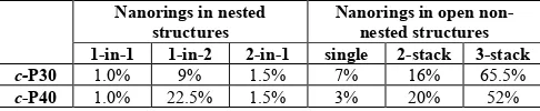
Table 1
|
Distribution of nanorings in identifiable nested, non-nested and open stacked structures from electrospray deposition under UHV.aNanorings in nested structures
Nanorings in open non-nested structures 1-in-1 1-in-2 2-in-1 single 2-stack 3-stack
c-P30 1.0% 9% 1.5% 7% 16% 65.5%
c-P40 1.0% 22.5% 1.5% 3% 20% 52%
a Statistics based on images of 522 c-P40 nanorings and 320 c-P30
nanorings, of which 324 and 119, respectively, were in overlapping disordered structures and are not included here; 1-in-1, 1-in-2 and 2-in-1 denote single-in-single, single-in-double and double-in-single nested structures.
The fraction of c-P30 and c-P40 in various nested and non-nested geometries is analysed in Table 1, showing that the single-in-double is by far the most common nested structure.
The conformation of the compact nested nanoring is most clearly resolved for nanoring A where a series of three ‘hairpin’ bends through ~180° deform the nanoring into a ‘C’ shape. The separation between porphyrin groups on neighbouring polymers is d = 2.1 ± 0.1 nm in regions where the curvature is small (for example the boundary between single-height nanorings slightly above the letter C in Fig. 4f), close to the separation measured for linear oligomers (see SI); this value is used in our estimate of the minimum size for nesting in the introduction. However, the separation of porphyrin groups in the inner and outer nanorings forming the nested structure can deviate from this value. In particular, the separation measured for structure A is in the range 1.6–1.8 nm in regions where the curvature of the inner nanoring is highest, i.e. close to the hairpin bends.
It is possible to map the porphyrin positions in the nested structure A, (see schematic in Fig. 4h), from which we estimate the elastic energy required to form the nested conformation. Approximating the shape to 30 segments with an angle αi between the ith and (i+1)th segments (see
Fig. 4h) we estimate,
(6)
where κB is the bending coefficient, estimated previously to be 0.07 and 0.03 nN nm2 for double and single layer nanorings respectively24. Accordingly we estimate E
B ≈ 2.6 eV for the nested double-height nanoring in Fig. 4f. Note that this energy, though large, is distributed over 60 porphyrin-butadiyne groups.
In considering the overall energy difference between a nested double/single-stacked nanoring and triply stacked structure we note that there is a gain in adsorption energy arising from the interaction of an additional nanoring with the gold surface. This must be greater than the energy required to elastically deform a coiled nanoring in order for the nested structure to be stable. The typical adsorption energies of porphyrins on Au(111) are in the
[image:4.595.301.544.172.222.2]5
range 2–4 eV; for example the adsorption energy of tetraphenylporphyrin on Au(111) has been calculated41 to be 3.3 eV. Since the overall adsorption energy would scale with N, this would result in an adsorption energy of ~100 eV for c-P30, much greater than the bending energy estimated above. For these large molecules which are composed of 4770 atoms high-level calculations of adsorption energies are not currently possible, but this order of magnitude argument illustrates that if there is a conformation available which can accommodate a nested structure, we would expect it to be energetically stable.
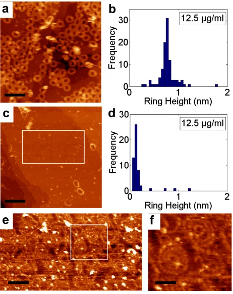
[image:5.595.58.289.309.600.2]In previous work on c-P24, we showed that the stacking is related to the choice of solvent26 (in particular it is suppressed through the addition of pyridine to the electrospray solution). To determine whether the nesting, and its combination with stacking, is also solvent dependent we have investigated layers formed by immersion under ambient conditions using a flame-annealed Au(111) thin film on mica as a substrate. STM images were then acquired under ambient conditions (see Methods and SI).
Figure 5. c-P30 deposited on Au(111) from solution (concentration 12.5 μg/ml): (a) stacked nanorings deposited from a toluene:methanol 3:5 mixture; (b) histogram of heights showing triple stacked nanorings; (c) single-height nanorings deposited from toluene; (d) histogram of heights showing a peak at ~0.1 nm corresponding to single-height nanorings; (e) zoomed image of highlighted area in (c) showing disordered arrangement of single-height c-P30; (f) further zoom of highlighted area in (e) showing nested structures. Scale bars: (a) 36 nm; (c) 36 nm (e) 18 nm; (f) 8 nm.
In Fig. 5a (12.5 µg/mL of c-P30 in 5:3 methanol:toluene) we see many bright nanorings with lateral dimensions ~13 nm, close to the value expected for c-P30. Many of the nanorings are slightly distorted from a circular shape and there are regions where
partially-ordered nanorings form a quasi-close packed hexagonal arrangement. A histogram of the heights of the nanorings in this image (Fig. 5b) shows a clear peak around 0.7 nm corresponding to a height of three stacked nanorings.
In contrast, deposition from a solution of c-P30 (12.5 µg/mL) in toluene (which is not compatible with electrospray) shows very few stacked nanorings (Fig. 5c). Under these conditions, we see single-height rings with a highly non-circular shape which form a disordered arrangement (Fig. 5e). A histogram (Fig. 5d) shows a clear peak at a height of ~0.1 nm confirming the predominance of single-height structures. These results confirm the dominant role of solvent in the stacking, and demonstrate that this effect is not limited to electrospray deposition.
For the surfaces prepared from toluene:methanol (3:5) we do not observe any nested structures (see Fig. 5a,b) and the triple height stacks are stable under STM imaging. The majority of nanorings (> 90%) are incorporated within the near-circular triple height stacks discussed above, with the remainder in less ordered, in many cases overlapping, structures. Thus, stacking occurs for both solution and electrospray deposition, but the combination of stacking and nesting is only observed using electrospray. This implies that the stacks are pre-formed in the methanol:toluene solution consistent with previous work. However, the nesting observed using methanol:toluene depends on the method of deposition, and is therefore likely formed on adsorption rather than in solution. Noting that in almost all cases the nesting observed for electrospray deposition involves double-in-single, or single-in-double structures, we propose that these arrangements originate from triple stacks of nanorings which are formed in solution and then relax through rearrangement when they impinge on the surface. In the light of this discussion we also interpret many of the complex structures of overlapping nanorings, for example in Fig. 4c, as multiple (commonly triple) stacks which impinge on the sample in electrospray deposition and partially collapse into slipped stacks or nested arrangements. In contrast, there are far fewer partially collapsed structures on solution deposition from toluene/methanol (Fig. 5a); stacking is retained under these conditions.
6
further evidence that the formation of such structures requires solvent-induced stacking as proposed above. We typically observe ~8 single-in-single nested structures in a 100 nm x 100 nm image on surfaces such as that shown in Fig. 5e, and ~10% of the surface is covered with nanorings adsorbed in nested arrangements. However, due to the flexibility of the single height nanorings there are no clear examples of near-circular ‘empty’ nanorings which might accommodate a coiled nested structure; the only nanorings which have a near-circular conformation in Fig. 5e serve as the outer ring of a nested structure.
As we show above in equation (1), a simple argument leads to a critical value of N ≈ 29 for which nesting would be sterically permitted, consistent with our observations (and also the absence of nesting for N = 24, the next smallest nanoring synthesised to date). However, the available area in the c-P30 nested structures is less than the maximum assumed in deriving this simple rule since the outer nanoring is not perfectly circular. Interestingly, although the single-height nested nanorings,
B and C, have a conformation which, overall, is very similar to the double-height nested ring, there are also bright features identified by arrows in Fig. 4f. We attribute these features to small sections where the nested nanoring adopts a conformation where, locally, the porphyrin groups are either non-parallel to the substrate, or there is a region of self-overlapping; this may be a route to accommodate the single nanoring in a nested structure even for cases where the available area is marginally lower than the critical size estimated above.
Conclusion
We have shown that Vernier-template directed synthesis can be extended to provide access to large cyclic polymers. The porphyrin nanorings c-P30, c-P40 and c-P50 are the largest monodisperse covalent synthetic macrocycles yet reported, with carbocyclic topologies of up to 750 C-C bonds. These cyclic polymers are highly amenable for imaging by STM, both under UHV, when deposited by electrospray, and under ambient conditions, deposited from solution. These STM experiments reveal that the larger rings, with 30 or more repeat units, form nested complexes, with one nanoring molecule folded inside another circular nanoring. Supramolecular nesting was observed under both UHV and solution-phase conditions. Under UHV, nesting is frequently combined with stacking, so that a stack of folded molecules sits inside a single-height extended ring, or such that a single folded molecule sits inside a stack of two extended ring molecules. The statistical distribution of these stacked/nested assemblies strongly suggests that they are formed, under UHV electrospray conditions, by the on-surface rearrangement of triple-decker nanoring stacks. This work illustrates the tendency for large macrocyclic molecules to undergo biomimetic self-assembly, and the power of STM for probing supramolecular processes.
Methods
Vernier-templated polymerisation of l-P10 in the presence of T6. The template T6 (0.68 mg, 0.68 µmol) and the linear porphyrin 10-mer l-P10 (4.7 mg, 0.41 µmol) were dissolved in CHCl3 (5.0 mL) and heated at 50 °C until clear solution formed. A catalyst solution was prepared by dissolving Pd(PPh3)2Cl2
(1.0 mg, 1.4 µmol), CuI (1.2 mg, 6.9 µmol) and 1,4-benzoquinone (3.0 mg, 28 µmol) in CHCl3 (700 µL) and
i-Pr2NH (60 µL). 250 µL of the catalysts solution was added to a solution of l-P10 and T6 at 0 °C and then stirred at 0 °C for 2 hours and then at 20 °C for 12 hours. The porphyrin oligomers mixture was separated from the catalysts by size-exclusion chromatography (Biobeads SX-1, CHCl3/10% pyridine) and further separated by recycling gel permeation chromatography to yield c-P10 (1.2 mg, 26%), c-P20 (0.8 mg, 17%), c-P30 (1.2 mg, 26%) and c-P40 (0.5 mg, 11%).
Scanning tunnelling microscopy: (i) UHV experiments - a solution of c-P10, c-P20, c-P30, c-P40 or c-P50 in toluene-methanol (3:1 by volume; concentration, 100 µm mL–1) was deposited on the substrate (gold on mica) by electrospray. Images were acquired in ultrahigh vacuum using electrochemically etched tungsten tips, in constant-current mode at room temperature; (ii) the samples in Fig. 5 were prepared by immersing a gold on mica substrate in a solution for 10 minutes. Further details are included in the SI.
References
1. Hunter, C. A. & Anderson, H. L. What is cooperativity? Angew. Chem. Int. Ed.48, 7488–7499 (2009).
2. Cheng, R. P. Beyond de novo protein design – de novo design of non-natural folded oligomers. Current Opinion Struct. Biol.14, 512–520 (2004).
3. Gan, Q., Ferrand, Y., Bao, C., Kauffmann, B., Grélard, A., Jiang, H. & Huc, I. Helix-rod host-guest complexes with shuttling rates much faster than disassembly. Science331, 1172–1175 (2011).
4. Sakai, N., Mareda, J. & Matile, S. Artificial β-barrels. Acc. Chem. Res.41, 1354–1365 (2008).
5. Kondratuk, D. V., Perdigao, L. M. A., O’Sullivan, M. C., Svatek, S., Smith, G., O’Shea, J. N., Beton, P. H. & Anderson, H. L. Two Vernier-templated routes to a 24-porphyrin nanoring. Angew. Chem. Int. Ed.51, 6696–6699 (2012).
6. Bartels, L. Tailoring molecular layers at metal surfaces. Nat. Chem.2, 87–95 (2010).
7. Kudernac, T., Lei, S., Elemans, J. A. A. W. & De Feyter, S. Two-dimensional supramolecular self-assembly:
nanoporous networks on surfaces. Chem. Soc. Rev.38, 402– 421 (2009).
8. Barth, J. V, Costantini, G. & Kern, K. Engineering atomic and molecular nanostructures at surfaces. Nature437, 671– 679 (2005).
9. Böhringer, M. et al. Two-dimensional self-assembly of supramolecular clusters and chains. Phys. Rev. Lett.1, 324– 327 (1999).
10. Yokoyama, T., Yokoyama, S., Kamikado, T., Okuno, Y. & Mashiko, S. Selective assembly on a surface of
supramolecular aggregates with controlled size and shape. Nature413, 619–621 (2001).
11. Barth, J. V et al. Building supramolecular nanostructures at surfaces by hydrogen bonding. Angew. Chem. Int. Ed.39, 1230–1234 (2000).
12. Griessl, S., Lackinger, M., Edelwirth, M., Hietschold, M. & Heckl, W. M. Self-assembled two-dimensional molecular host-guest architectures from trimesic acid. Single Mol.3, 25–31 (2002).
13. Theobald, J. A., Oxtoby, N. S., Phillips, M. A., Champness, N. R. & Beton, P. H. Controlling molecular deposition and layer structure with supramolecular surface assemblies. Nature424, 1029–31 (2003).
7 15. Griessl, S. J. H. et al. Incorporation and manipulation of
coronene in an organic template structure. Langmuir20, 9403–7 (2004).
16. Blunt, M. O. et al. Guest-induced growth of a surface-based supramolecular bilayer. Nat. Chem.3, 74–8 (2011). 17. Spillmann, H. et al. Hierarchical assembly of
two-dimensional homochiral nanocavity arrays. J. Am. Chem. Soc.125, 10725–8 (2003).
18. Furukawa, S. et al. Structural transformation of a two-dimensional molecular network in response to selective guest inclusion. Angew. Chem. Int. Ed. 46, 2831–2834 (2007).
19. Nath, K. G. et al. Rational modulation of the periodicity in linear hydrogen-bonded assemblies of trimesic acid on surfaces. J. Am. Chem. Soc.128, 4212–4213 (2006). 20. Klappenberger, F. et al. Conformational adaptation in
supramolecular assembly on surfaces. ChemPhysChem8, 1782–1786 (2007).
21. Jung, T. A., Schlittler, R. R. & Gimzewski, J. K. Conformational identification of individual adsorbed molecules with the STM. Nature386, 696–698 (1997). 22. Taylor, P. N., Huuskonen, J., Rumbles, G., Aplin, R. T.,
Williams, E. & Anderson, H. L. Conjugated porphyrin oligomers from monomer to hexamer. Chem. Commun. 909–910 (1998).
23. Sprafke, J. K. et al. Belt-shaped π-systems: relating geometry to electronic structure in a six-porphyrin nanoring. J. Am. Chem. Soc.133, 17262–17273 (2011).
24. Saywell, A., Sprafke, J. K., Esdaile, L. J., Britton, A. J., Rienzo, A., Anderson, H. L., O’Shea, J. N. & Beton, P. H. Conformation and packing of porphyrin polymer chains deposited using electrospray on a gold surface. Angew. Chem. Int. Ed.49, 9136–9139 (2010).
25. O’Sullivan, M. C., Sprafke, J. K., Kondratuk, D. V., Rinfray, C., Claridge, T. D. W., Saywell, A., Blunt, M. O., O’Shea, J. N., Beton, P. H., Malfois, M. & Anderson, H. L. Vernier templating and synthesis of a 12-porphyrin nanoring. Nature469, 72–75 (2011).
26. Svatek, S. A., Perdigão, L. M. A., Stannard, A., Wieland, M. B., Kondratuk, D. V., Anderson, H. L., O'Shea, J. N. & Beton, P. H. Mechanical stiffening of porphyrin nanorings through supramolecular columnar stacking. Nano Lett, 13, 3391–3395 (2013).
27. Wieland, M. B. et al. Height dependent molecular trapping in stacked cyclic porphyrin nanorings. Chem. Commun.50, 7332–7335 (2014).
28. Bielawski, C. & Grubbs, R. H. Living ring-opening metathesis polymerization. Prog. Pol. Sci.32, 1–29 (2007). 29. Semlyen, J. A., “Cyclic Polymers”, Kluwer Academic, 2nd
ed. (2000).
30. Jia, Z. & Monteiro, M. J. Cyclic polymers: methods and strategies. J. Pol. Scie. Pol. Chem.50, 2085–2097 (2012). 31. Mayor, M. & Didschies, C. A giant conjugated molecular
ring. Angew. Chem. Int. Ed. 42, 3176–3179 (2003). 32. Aggarwal, A. V. et al. Fluctuating exciton localizations in
giant π-conjugated spoked-wheel macrocycles. Nature Chem.5, 964–970 (2013).
33. Hori, T., Peng, X., Aratani, N., Takagi, A., Matsumoto, T., Kawai, T., Yoon, Z. S., Yoon, M.-C., Yang, J., Kim, D. &
Osuka, A. Synthesis of nanometer-scale porphyrin wheels of variable size. Chem. Eur. J. 14, 582–595 (2008).
34. Hoffmann, M., Kärnbratt, J., Chang, M.-H., Herz, L. M., Albinsson, B. & Anderson, H. L. Enhanced π-conjugation around a porphyrin [6]nanoring. Angew. Chem. Int. Ed. 47, 4993–4996 (2008).
35. Hoffmann, M., Wilson, C. J., Odell, B. & Anderson H. L. Template-directed synthesis of a π-conjugated porphyrin nanoring. Angew. Chem. Int. Ed. 46, 3122–3125 (2007). 36. Mahabadi, H. K. & Rudin, A. Effect of solvent on
concentration dependence of hydrodynamic volumes and GPC elution volumes. Pol. J.11, 123–131 (1979).
37. Grubisic, Z., Rempp, P. & Benoit, H. A universal calibration for gel permeation chromatography. J. Polym. Sci. B Pol. Lett.5, 753–759 (1967).
38. Fukatsu, M. & Kurata, M. Hydrodynamic properties of flexible ring macromolecules. J. Chem. Phys.44, 4539– 4545 (1966).
39. Dodgson, K. & Semlyen, J. A. Studies of cyclic and linear poly(dimethylsiloxanes): 1. Limiting viscosity number-molecular weight relationships. Polymer18, 1265–1268 (1977).
40. Kricheldorf, H. R. Cyclic polymers: synthetic strategies and physical properties. J. Polym. Sci. Part A: Polym. Chem.48, 251–284 (2010).
41. Brede, J. et.al. Dynamics of molecular self-ordering in tetraphenyl porphyrin monolayer on metallic substrates. Nanotechnology20 275602 (2009).
Acknowledgements
We thank the Engineering and Physical Sciences Research Council (EPSRC) and the Clarendon Fund for support; the EPSRC mass spectrometry service (Swansea) for mass spectra.
Author contributions
H.L.A. and D.V.K. designed the synthesis of cyclic polymers. P.H.B., L.M.A.P., J.N.O.S. and A.M.S.E. developed the protocols required for STM imaging. Synthesis and solution-phase characterisation were carried out by D.V.K. UHV and ambient STM experiments were carried out by L.M.A.P. and A.M.S.E. respectively. The manuscript was written by D.V.K., H.L.A. and P.H.B. All authors contributed towards data analysis and edited the manuscript.
Additional information
The authors declare no competing financial interests. Supplementary information accompanies this paper at www.nature.com/naturechemistry. Reprints and permission information is available online at
http://www.nature.com/reprints. Correspondence and requests for materials should be addressed to H.L.A. or P.H.B.
Competing financial interests
1 Department of Chemistry, University of Oxford, Oxford OX1 3TA, UK. 2 School of Physics & Astronomy, University of
Nottingham, Nottingham, NG7 2RD, UK. *e-mail: harry.anderson@chem.ox.ac.uk, peter.beton@nottingham.ac.uk
S1
Supplementary Information
Supramolecular nesting of cyclic polymers
Dmitry V. Kondratuk,† Luís M. A. Perdigão,‡ Ayad M. S. Esmail,‡ James N. O’Shea,‡ Peter H. Beton‡* and Harry L. Anderson†*
†Department of Chemistry, University of Oxford, Oxford, OX1 3TA, UK
‡School of Physics & Astronomy, University of Nottingham, Nottingham, NG7 2RD, UK
Table of Contents
A. Materials and Methods
S2
B. Synthetic Procedures
S2
B1. Synthesis of linear porphyrin building blocks
S2
Synthesis of
l
-P2
THS,THS,
l
-P10
THS,THSand
l
-P18
THS,THSby coupling of
l
-P8
and the excess of
l
-P1
H,THSS3
B2. Oligomerisation of
l
-P10
S3
B2a. Full deprotection of
l
-P10
THS,THSS3
B2b. Oligomerisation of
l
-P10
in the absence of templates
S3
B2c. Oligomerisation of
l
-P10
in the presence of
T6
S3
B2d. Oligomerisation of
l
-P10
in the presence of
T8
S4
C. Characterisation
S6
C1. Linear porphyrin 10-mer
l-
P10
THS,THSS6
C1a.
1H-NMR analysis
S6
C1b. MALDI-ToF
S6
C2. Linear porphyrin 10-mer
l
-P18
THS,THSS7
C2a.
1H-NMR analysis
S7
C2b. MALDI-ToF
S7
C3. Cyclic porphyrin 10-mer
c
-P10
S8
C3a.
1H-NMR analysis
S8
C3b. MALDI-ToF
S8
C4. Cyclic porphyrin 20-mer
c
-P20
S9
C4a.
1H-NMR analysis
S9
C4b. MALDI-ToF
S9
C5. Cyclic porphyrin 30-mer
c
-P30
S10
C5a.
1H-NMR analysis
S10
C5b. MALDI-ToF
S10
C6. Cyclic porphyrin 40-mer
c
-P40
S11
C6a.
1H-NMR analysis
S11
C6b. MALDI-ToF
S11
C7. Cyclic porphyrin 50-mer
c
-P50
S12
C7a.
1H-NMR analysis
S12
C7b. MALDI-ToF
S12
D. UV/Vis/NIR absorption of
c
-P10,
c
-P20,
c
-P30 and
c
-P40
S13
E. Scanning tunnelling microscopy
S13
E1. Preparation and imaging of gold surface
S13
E2. Electrospray deposition
S13
E3. Image of linear oligomer
l
-
P4
S13
E4. Additional images of
c
-P10
,
c
-P20
,
c
-P30
and
c
-P40
S14
E5. Additional images of
c
-P50
S15
E6. Height profiles of nested and stacked nanorings
S16
S2
A. Materials and Methods
Dry CHCl
3, CH
2Cl
2and toluene were obtained by passing through alumina under N
2pressure. All
other reagents were used as commercially supplied. NMR data were collected at 500 MHz using a
Bruker AVII 500 or DRX 500 or at 400 MHz using a Bruker DPX 400 at 298 K. Chemical shifts
are quoted as parts per million (ppm) relative to residual CHCl
3at
δ
7.27 ppm and coupling
constants (
J
) are reported in Hertz. MALDI-ToF spectra were measured at the EPSRC National
Mass Spectrometry service (Swansea) using the Applied Biosystems Voyager DE-STR.
Room
temperature UV-vis-NIR absorbance measurements were recorded with a Perkin-Elmer Lambda 20
photospectrometer. Size exclusion chromatography (SEC) was carried out using Bio-Beads S-X1,
200-400 mesh (Bio Rad). Analytical and semi-preparative GPC was carried out on Shimadzu
Recycling GPC system equipped with LC-20 AD pump, SPD-20A UV detector and a set of
JAIGEL 3H (20
×
600 mm) and JAIGEL 4H (20
×
600 mm) columns in toluene/1% pyridine as
eluent with a flow rate of 3.5 mL/min.
B. Synthetic Procedures
Half and fully-deprotected porphyrin monomer
l
-P1
H,THSand
l
-P1
S1, fully-deprotected dimer
l
-P2
S1,
fully-deprotected trimer
l
-P3
S2, fully-deprotected octamer
l
-P8
S3, pentadentate template
T5
S4,
hexadentate template
T6
S2and octadentate template
T8
S5were synthesised using published
procedures or adopting them. The Pd/Cu co-catalyst system with 1,4-benzoquinone as an oxidant
was used throughout for homocoupling.
S6B1. Synthesis of linear porphyrin building blocks
Synthesis of
l
-P2
THS,THS,
l
-P10
THS,THSand
l
-P18
THS,THSby coupling of
l
-P8 and excess
l
-P1
H,THSFully-protected linear porphyrin 8-mer
l
-P8
THS,THS(54.0 mg, 5.8
µ
mol) was dissolved in CH
2Cl
2(30.0 mL) and the solution degassed. Tetra-
n
-butylammonium fluoride (1.0 M in THF, 160
µ
L,
0.16 mmol) was added and the reaction mixture stirred at 20 °C for 1 h. under N
2atmosphere. The
reaction was quenched with MeOH (1.0 mL), the volume reduced, the
l
-P8
precipitated with MeOH
(50 mL), filtered off and dried in high vacuum. All obtained
l
-P8
and half-deprotected porphyrin
monomer
l
-P1
H,THS(308 mg, 0.225 mmol) were dissolved in the mixture of toluene (100 mL) and
pyridine (1.0 mL). A catalyst solution was prepared by dissolving
dichlorobis(triphenylphosphine)-palladium(II) (107 mg, 0.152 mmol), copper(I) iodide (263.3 mg, 1.38 mmol) and
1,4-benzoquinone (248.8 mg, 2.30 mmol) in the mixture of toluene (80.0 mL) and freshly distilled
i
-Pr
2NH (18.0 mL) and added to the solution of
l
-P8
and
l
-P1
H,THS. The reaction mixture was stirred
at 20 °C for 3 h, after which half of the initial amount of the catalyst solution was added and the
mixture stirred at 60 °C for 2 h. Once UV-Vis spectroscopy showed no changes, the reaction
mixture was passed through short silica column (CHCl
3/1% pyridine) to remove the catalysts and
then over a size exclusion column (Biobeads SX-1 in toluene/1% pyridine) to remove the
1,4-benzoquinone. Preparative GPC (toluene/10% pyridine) followed by the recycling GPC yielded 242
mg (79%) of
l
-P2
THS,THS, 47 mg (70%) of
l
-P10
THS,THSand 4 mg (7%) of
l
-P18
THS,THSas brown
S3
l
-P10
THS,THS:
1H-NMR (400 MHz, CDCl
3/1%
d
5-pyridine):
δ
H9.77
–9.73 (m, 36H, -Ar
H
β), 9.54 (d,
4H,
J
= 4.5 Hz, -Ar
H
β), 8.96
–8.93 (m, 36H, -Ar
H
β), 8.84 (d, 4H,
J
= 4.4 Hz, -Ar
H
β), 7.28
–7.21 (m,
40H, Ar-
H
ortho), 6.80
–6.77 (m, 20H, Ar-
H
para), 3.99 (m, 80H, -OC
H
2), 1.76
–1.67 (m, 92H, -C
H
2),
1.65
–1.59 (m, 12H, -C
H
2), 1.42
–1.07 (m, 424H, -C
H
2), 0.89
–0.85 (m, 12H, -C
H
2), 0.74
–0.66 (m,
138H, -C
H
3);
m/z
(MALDI-ToF) 11419 (C
716H
898N
40O
40Zn
10, M
+requires 11415);
λ
max(CHCl
3/ 1% pyridine) / nm (log
ε
) 469 (6.01), 591 (4.91), 809 (5.73).
l
-P18
THS,THS:
1H-NMR (400 MHz, CDCl
3/1%
d
5-pyridine):
δ
H9.74–9.70 (m, 68H, -Ar
H
β), 9.51(d,
4H,
J
= 4.5 Hz, -Ar
H
β), 8.93–8.89 (m, 68H, -Ar
H
β), 8.81 (d, 4H,
J
= 4.5 Hz, -Ar
H
β), 7.23–7.17 (m,
72H, Ar-
H
ortho), 6.77–6.75 (m, 36H, Ar-
H
para), 3.94 (m, 144H, -OC
H
2), 1.71–1.64 (m, 156H, -C
H
2),
1.61–1.55 (m, 12H, -C
H
2), 1.35–0.99 (m, 774H, -C
H
2), 0.85–0.80 (m, 12H, -C
H
2), 0.70–0.60 (m,
234H, -C
H
3);
m/z
(MALDI-ToF) 20181 (C
1260H
1554N
72O
72Zn
18, M
+requires 20093);
λ
max(CHCl
3/ 1% pyridine) / nm (log
ε
) 471 (6.33), 592 (5.22), 815 (6.13).
B2. Oligomerisation of
l-P10
B2a. Full deprotection of
l
-P10
THS,THSFully-protected linear porphyrin 10-mer
l
-P10
THS,THS(2.9 mg, 0.25
µ
mol) was dissolved in the
mixture of CH
2Cl
2(0.5 mL) and pyridine (0.5
µ
L) and the solution degassed. Tetra-
n
-butylammonium fluoride (1.0 M in THF, 2
µ
L, 2
µ
mol) was added and the reaction mixture stirred
at 20 °C for 20 min under N
2atmosphere. The reaction was quenched with MeOH (10
µ
L), the
volume reduced, the
l
-P10
precipitated with MeOH (5 mL), filtered out and dried in high vacuum
and used further without characterisation.
B2b. Oligomerisation of
l
-P10 in the absence of templates
The oligomerisation of
l
-P10
in the absence of templates was carried out without separation of
products to obtain only their distribution. The authenticity of the products was confirmed by
comparison of corresponding retention times (Fig. 2a of the main text).
B3c. Oligomerisation of
l
-P10 in the presence of T6
The template
T6
(0.68 mg, 0.68
µ
mol) and the linear porphyrin 10-mer
l
-P10
(4.7 mg, 0.41
µ
mol)
were dissolved in CHCl
3(5.0 mL) and heated at 50 °C until clear solution formed. A catalyst
solution was prepared by dissolving Pd(PPh
3)
2Cl
2(1.0 mg, 1.41
µ
mol), CuI (1.2 mg, 6.9
µ
mol) and
1,4-benzoquinone (3.0 mg, 27.9
µ
mol) in CHCl
3(700
µ
L) and
i
-Pr
2NH (60
µ
L). 250
µ
L of the
catalysts solution was added to a solution of
l
-P10
and
T6
at 0 °C and then stirred at 0 °C for 2 h.
and then at 20 °C for 12 h. Once analytical GPC confirmed full conversion of the
l
-P10
, the
porphyrin oligomers mixture was separated from the catalysts by size-exclusion chromatography
(Biobeads SX-1, CHCl
3/10% pyridine) and further separated by recycling gel permeation
chromatography (Fig. S1a) to yield
c
-P10
(1.2 mg, 26%),
c
-P20
(0.8 mg, 17%),
c
-P30
(1.2 mg,
26%) and
c
-P40
(0.5 mg, 11%).
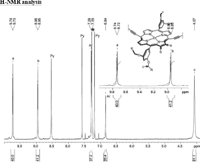
c
-P10
:
1H-NMR (500 MHz, CDCl
3/1%
d
5-pyridine):
δ
H9.74 (d, 40H,
J
= 4.5 Hz, -Ar
H
β), 8.96 (d,
40H,
J
= 4.5 Hz, -Ar
H
β), 7.29 (m, 40H, Ar-
H
ortho), 6.84 (m, 20H, Ar-
H
para), 4.07 (s br, 80H,
S4
(m, 120H, -C
H
3);
m/z
(MALDI-ToF) 10852 (C
680H
820N
40O
40Zn
10, M
+requires 10848);
λ
max(CHCl
3/ 1% pyridine) / nm (log
ε
) 473 (5.91), 595 (4.82), 808 (5.68).
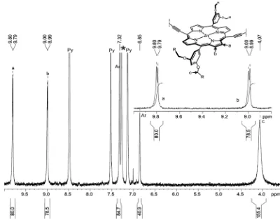
c
-P20
:
1H-NMR (400 MHz, CDCl
3/1%
d
5-pyridine):
δ
H9.80 (d, 80H,
J
= 4.5 Hz, -Ar
H
β), 8.96 (d,
80H,
J
= 4.5 Hz, -Ar
H
β), 7.28 (m, 80H, Ar-
H
ortho), 6.85 (m, 40H, Ar-
H
para), 4.07 (s br, 160H,
-OC
H
2), 1.81
–1.78 (m, 160H, C
H
2), 1.46
–1.40 (m, 160H, C
H
2), 1.31
–1.12 (m, 640H, C
H
2), 0.78
–0.74 (m, 240H, -C
H
3);
m/z
(MALDI-ToF) 21701 (C
1360H
1640N
80O
80Zn
20, M
+requires 21696);
λ
max(CHCl
3/ 1% pyridine) / nm (log
ε
) 472 (6.21), 594 (5.12), 813 (6.02).
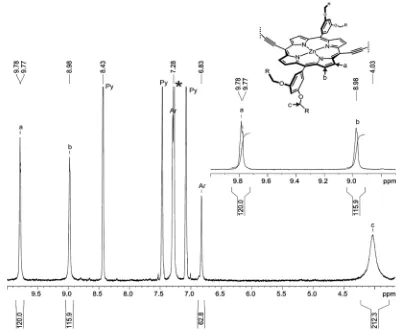
c
-P30
:
1H-NMR (400 MHz, CDCl
3/1%
d
5-pyridine):
δ
H9.78 (m, 120H, -Ar
H
β), 8.98 (m, 120H,
-Ar
H
β), 7.28 (m, 120H, Ar-
H
ortho), 6.83 (m, 60H, Ar-
H
para), 4.03 (s br, 240H, -OC
H
2), 1.76 (m,
240H, C
H
2), 1.40 (m, 240H, C
H
2), 1.25
–1.10 (m, 960H, C
H
2), 0.71 (m, 360H, -C
H
3);
m/z
(MALDI-ToF) 32681 (C
2040H
2460N
120O
120Zn
30, M
+requires 32543);
λ
max(CHCl
3/ 1% pyridine) / nm (log
ε
)
473 (6.43), 593 (5.33), 817 (6.27).
c
-P40
:
1H-NMR (400 MHz, CDCl
3/1%
d
5-pyridine):
δ
H9.77 (m, 160H, -Ar
H
β), 8.98 (d, 160H,
-Ar
H
β), 7.28 (m, 160H, Ar-
H
ortho), 6.80 (m, 80H, Ar-
H
para), 3.99 (s br, 320H, -OC
H
2), 1.72 (m,
320H, C
H
2), 1.36 (m, 320H, C
H
2), 1.23
–1.07 (m, 1280H, C
H
2), 0.70
–0.67 (m, 480H, -C
H
3);
m/z
(MALDI-ToF) 43475 (C
2720H
3280N
160O
160Zn
40, M
+requires 43391);
λ
max(CHCl
3/ 1% pyridine) /
nm (log
ε
) 474 (6.50), 593 (5.40), 819 (6.34).
B2d. Oligomerisation of
l
-P10 in the presence of T8
The template
T8
(0.98 mg, 0.42
µ
mol) and the linear porphyrin 10-mer
l
-P10
(4.5 mg, 0.41
µ
mol)
were dissolved in CHCl
3(5.3 mL) and heated at 50 °C until clear solution formed. A catalyst
solution was prepared by dissolving Pd(PPh
3)
2Cl
2(1.0 mg, 1.41
µ
mol), CuI (1.2 mg, 6.9
µ
mol) and
1,4-benzoquinone (3.0 mg, 27.9
µ
mol) in CHCl
3(700
µ
L) and
i
-Pr
2NH (60
µ
L). 260
µ
L of the
catalysts solution was added to a solution of
l
-P10
and
T8
at 0 °C and then stirred at 0 °C for 2 h
after which the initial amount of the catalysts solution was added and the mixture stirred at 0 °C for
2 h and then at 20 °C for 10 h. After that 1560
µ
L of the catalyst solution was added in three equal
portions – after 14 h. of stirring and further stirred at 40 °C, after 19 h. of stirring and further stirred
at 50 °C and after 17 h. of stirring and further stirred at 50 °C. Once analytical GPC confirmed full
conversion of the
l
-P10
, the porphyrin oligomers mixture was separated from the catalysts by
size-exclusion chromatography (Biobeads SX-1, CHCl
3/10% pyridine) and further separated by
recycling gel permeation chromatography (Fig. S1b) to yield
c
-P10
(0.3 mg, 7%),
c
-P20
(0.3 mg,
7%),
c
-P30
(0.7 mg, 16%),
c
-P40
(1.2 mg, 27%) and
c
-P50
(0.6 mg, 13%).
c
-P10
:
1H-NMR as reported above.
c
-P20
:
1H-NMR as reported above.
c
-P30
:
1H-NMR as reported above.
c
-P40
:
1H-NMR as reported above.
c
-P50
:
1H-NMR (400 MHz, CDCl
3/1%
d
5-pyridine):
δ
H9.82 (m, 200H, -Ar
H
β), 9.01 (d, 200H,
-Ar
H
β), 7.34 (m, 200H, Ar-
H
ortho), 6.86 (m, 100H, Ar-
H
para), 4.06 (s br, 400H, -OC
H
2), 1.81 (m,
400H, C
H
2), 1.44 (m, 400H, C
H
2), 1.31
–1.14 (m, 1600H, C
H
2), 0.77 (m, 600H, -C
H
3);
m/z
S5
Figure S1. Analytical recycling GPC traces (toluene/1% pyridine, detection at 500 nm) of the crude reaction mixtures of coupling l-P10 in the presence of T6 (a) or T8 (b). Each sample was recycled 4 times. Resolved peaks were collected after 1st (l-P10 and c-P10) and 2nd (c-P20) cycles to compensate for the broadening of the chromatogram. The catalysts and 1,4-benzoquinone have been removed by passing a sample of the reaction mixture through a short GPC column in CHCl3/10% pyridine as eluent. Analytical yields were deduced by integration of resolved GPC peak areas, from the absorption at 500 nm, assuming that all species have the same extinction coefficient per porphyrin unit at this wavelength, and that there is no adsorption of material onto the GPC columns.
[image:13.595.202.404.508.732.2]S6
C. Characterisation
[image:14.595.63.526.132.471.2]C1. Linear porphyrin 10-mer
l-P10
THS,THSC1a.
1H-NMR analysis
Figure S3. 1H NMR spectrum of l-P10
THS,THS with zoom on the β-pyrrole region (400 MHz, CDCl3/1% d5-pyridine).
C1b. MALDI-ToF
Figure S4. MALDI-ToF analysis of l-P10THS,THS. The major peak corresponds to l-P10THS,THS (m/z 11419, expected
[image:14.595.100.500.527.753.2]S7
C2. Linear porphyrin 18-mer
l-P18
THS,THSC2a.
1H-NMR analysis
Figure S5. 1H NMR spectrum of l-P18THS,THS with zoom on the β-pyrrole region (400 MHz, CDCl3/1% d5-pyridine).
C2b. MALDI-ToF
Figure S6. MALDI-ToF analysis of l-P18THS,THS. The major peak corresponds to l-P18THS,THS (m/z 20181 expected
[image:15.595.62.532.83.436.2] [image:15.595.81.514.467.738.2]S8
C3. Cyclic porphyrin 10-mer
c-P10
[image:16.595.88.500.74.410.2]C3a.
1H-NMR analysis
Figure S7. 1H NMR spectrum of c-P10 with zoom on the β-pyrrole region (500 MHz, CDCl
3/1% d5-pyridine).
C3b. MALDI-ToF
[image:16.595.88.500.456.715.2]S9
C4. Cyclic porphyrin 20-mer
c-P20
[image:17.595.95.495.95.409.2]C4a.
1H-NMR analysis
Figure S9. 1H NMR spectrum of c-P20 with zoom on the β-pyrrole region (400 MHz, CDCl
3/1% d5-pyridine).
C4b. MALDI-ToF
[image:17.595.80.511.458.723.2]
S10
C5. Cyclic porphyrin 30-mer
c-P30
C5a.
1H-NMR analysis
Figure S11. 1H NMR spectrum of c-P30 with zoom on the β-pyrrole region (400 MHz, CDCl3/1% d5-pyridine).
[image:18.595.97.499.95.425.2]C5b. MALDI-ToF
[image:18.595.74.507.473.712.2]S11
C6. Cyclic porphyrin 40-mer
c-P40
C6a.
1H-NMR analysis
Figure S13. 1H NMR spectrum of c-P40 with zoom on the β-pyrrole region (400 MHz, CDCl
[image:19.595.104.498.91.424.2]3/1% d5-pyridine).
C6b. MALDI-ToF
[image:19.595.72.511.464.705.2]S12
C7. Cyclic porphyrin 50-mer
c-P50
C7a.
1H-NMR analysis
Figure S15. 1H NMR spectrum of c-P50 with zoom on the β-pyrrole region (400 MHz, CDCl
3/1% d5-pyridine)
C7b. MALDI-ToF
[image:20.595.92.502.94.391.2] [image:20.595.70.527.429.685.2]S13
[image:21.595.64.540.100.270.2]D.
UV/Vis/NIR absorption of
c
-P10,
c
-P20,
c
-P30 and
c
-P40
Figure S17. Optical absorption spectra of c-P10 (black line), c-P20 (red line), c-P30 (orange line) and c-P40 (blue line) measured in (a) CHCl3 and (b) CHCl3 / 1% pyridine
E.
Scanning tunnelling microscopy
E1. Preparation and imaging of gold surfaces
A gold on mica substrate (4 mm
×
8 mm, thickness 300 nm; supplied commercially by Georg
Albert PVD) was loaded into a UHV system with a base pressure of 3
×
10
–10Torr. The sample was
cleaned by Ar ion sputtering (6
×
10
–6Torr, 0.8 KeV, ~2 µA) and subsequent annealing (400 °C).
STM images were acquired using electrochemically etched tungsten tips, while operating in
constant current mode at room temperature (typically sample bias –2 <
V
s< –1.8 V, and set-point
current
I
s= 30 pA). Images of the surface obtained after the sputter-anneal cycle show the
characteristic (22
×
√
3) herringbone reconstruction of the Au(111) surface. For ambient
experiments, gold on mica pieces (1 cm
×
1 cm) were annealed in a butane flame. Before
immersion in a solution of nanorings the substrate was allowed to cool to room temperature and
STM images were acquired to characterise the quality of the surface termination. Nanorings were
deposited by immersion and the susbstrates were then dried in a nitrogen stream. An STM operating
under ambient conditions employing tips cut from Pt/Ir wire was used to acquire images. All
images were processed using WSxM software.
S7E2. Electrospray deposition
l-P4
(see below),
c
-P10
, c
-P20
,
c
-P30
,
c
-P40
and
c-
P50
were dissolved in 75% toluene, 25%
methanol (by volume) to give a concentration of ~100 µg/mL. During UHV-ESD a bias of ~2 kV
was applied to the emitter to produce the electrospray event, with the pressure rise in the
preparation chamber due to the introduction of the molecular beam measured to be of the order 5
×
10
–6mbar.
E3. Image of linear oligomer
l
-P4
The STM image in Fig. S18 shows the linear oligomer
l
-P4
adsorbed on Au(111) following
deposition by electrospray. Images are acquired prior to annealing. The spacing of porphyrins in
neighbouring oligomers,
Δ
= 2.0 ± 0.15 nm
, close to the value of the single-height nanorings
discussed in the main text.
(a)
(b)
CHCl
3with
S14
Figure S18. STM Image of the linear porphyrin tetramer l-P4 deposited on Au(111). The spacing between porphyrin, Δ = 2.0 ± 0.15 nm.
E4. Additional images of
c
-P10,
c
-P20,
c
-P30 and
c
-P40 acquired in UHV experiments
Large area STM images show the presence of many nanometer-sized rings (Fig. S18–21). The small
area images allow visualising individual porphyrin units and determining the number of porphyrin
units in each chain. As expected,
c-
P10
,
c
-P20
,
c
-P30
and
c
-P40
are the main components present
in the samples indicating their high purity.
[image:22.595.113.483.441.629.2]S15
Figure S20. STM images of c-P30.
Figure S21. Large (a) and small (b) area STM image of c-P40.
E5. Additional images of
c
-P50
The sample of
c
-P50
used in the experiment was synthesised as described in Section B3e. The
recycling GPC analysis as well as MALDI-ToF analysis (Fig. S17) showed that the sample of
[image:23.595.216.384.581.750.2]c
-P50
contains traces of other porphyrin oligomers, however due to the small amount of the isolated
material (0.6 mg) it was decided to acquire images (Fig. S22) of the material without further
purification.
S16
E6. Height profiles of nested and stacked nanorings
[image:24.595.182.414.133.290.2]We show below the height profiles extracted from the images in the main text. The typical
topographic heights of single, double and triple stacked nanorings are ~0.15, 0.4 and 0.75 nm
respectively.
[image:24.595.142.450.357.480.2]Figure S23. Profiles showing the heights of different stacked and nested c-P30. Colour coding provides the correspondence between profile and position on the image. The green and red profiles show the internal and encapsulating rings in single-in-double and double-in-single nested structures respectively.
Figure S24. Profiles showing the heights of nested c-P40. In this particular image the nested arrangement crosses a terrace step in the underlying gold surface. The difference in height between the ‘double’ and ‘single’ on the same terrace is close to the expected value of 0.34 nm.
[image:24.595.166.435.550.689.2]S17
Figure S26. Profiles showing the heights of c-P30 deposited from toluene. A uniform contrast is observed
corresponding to single height nanorings. The arrows on the profile indicate the points marked by crosses on the image.
F. References
S1. Chang, M.-H., Hoffmann, M., Anderson, H. L. & Herz, L. M. Dynamics of excited-state conformational relaxation and electronic delocalization in conjugated porphyrin oligomers, J. Am. Chem. Soc. 125, 10532– 10533 (2003).
S2. Hoffmann, M., Kärnbratt, J., Chang, M.-H., Herz, L. M., Albinsson, B. & Anderson H. L. Enhanced π conjugation around a porphyrin[6] nanoring, Angew. Chem. Int. Ed. 47, 4993–4996 (2008).
S3. Taylor, P. N. & Anderson, H. L. Cooperative self-assembly of double-strand conjugated porphyrin ladders, J. Am. Chem. Soc. 121, 11538–115454 (1999).
S4. Hogben, H. J., Sprafke, J. K., Hoffmann, M., Pawlicki, M. & Anderson, H. L. Stepwise effective molarities in porphyrin oligomer complexes: preorganization results in exceptionally strong chelate cooperativity. J. Am. Chem. Soc 133, 20962–20969 (2011).
S5. Hoffmann, M., Wilson, C. J., Odell, B. & Anderson H. L. Template-directed synthesis of a π-conjugated porphyrin nanoring. Angew. Chem. Int. Ed. 46, 3122–3125 (2007).
S6. Williams, V. E. & Swager, T. M. An improved synthesis of poly(p-phenylenebutadiynylene)s, J. Polym. Sci., Part A: Polym. Chem. 38, 4669–4676 (2000).