Thermal design optimization of novel modular power converter
assembly enabling higher performance, reliability and availability
P. Cova
a,*, N. Delmonte
a, A.K. Solomon
b, A. Castellazzi
baDipartimento di Ingegneria dell’Informazione, University of Parma, Italy
bPower Electronics, Machines and Control Group, University of Nottingham, United Kingdom
Abstract
An alternative integration scheme for a half-bridge switch using 70 m thin Si IGBTs and diodes is presented. This flat switch, which is designed for high-frequency application with high power density, exhibits high strength, high toughness, low parasitic inductance and high thermal conductivity. Such a novel assembly approach is suitable to optimize performance, reliability and availability of the power system in which it is used. The paper focuses on the thermal performance of this assembly at normal and extreme operating conditions, studied by means of FEM thermo-fluidynamic simulations of the module integrated with connectors and liquid cooler, and thermal measurement performed on an early prototype. Improved solutions are also investigated by the FE model.
*Corresponding author.
Tel. +39 0521 905818; Fax: +39 0521 905822 1. Introduction
Power modules are widely spread, for various applications, such as industrial electric motor driving and welding, automotive and conversion of renewable energies. Required features of the power converters are increasing in terms of occupied volume, power quality, efficiency, reliability, maintainability, modularity, and cost. Innovative solutions can be found in literature for specific issues as the cooling integration to the module [1]-[5], or highly integrated systems to reduce as much as possible the stray inductances [6], sometime with gate-drivers, power stage, and DC-link in the same package, as in [7]. This last feature is particularly important in power switches designed for high frequency (e.i. MHz) application.
From the reliability point of view, for high power density assemblies, optimization of the thermal design is a key issue and must be carefully conducted by coupling thermal characterization performed on early prototypes and 3D thermal modeling.
In this work, we show the development of a modular prototype integrating a Half Bridge Switch
(HBS), a double-side liquid cooler and customized connectors to interface quickly gate-driver, input, and load side PCBs and maximize the maintainability, that could be worse in a single package integrated system. The paper mainly focuses on the study of the thermal performance of the system, by using FEM analysis.
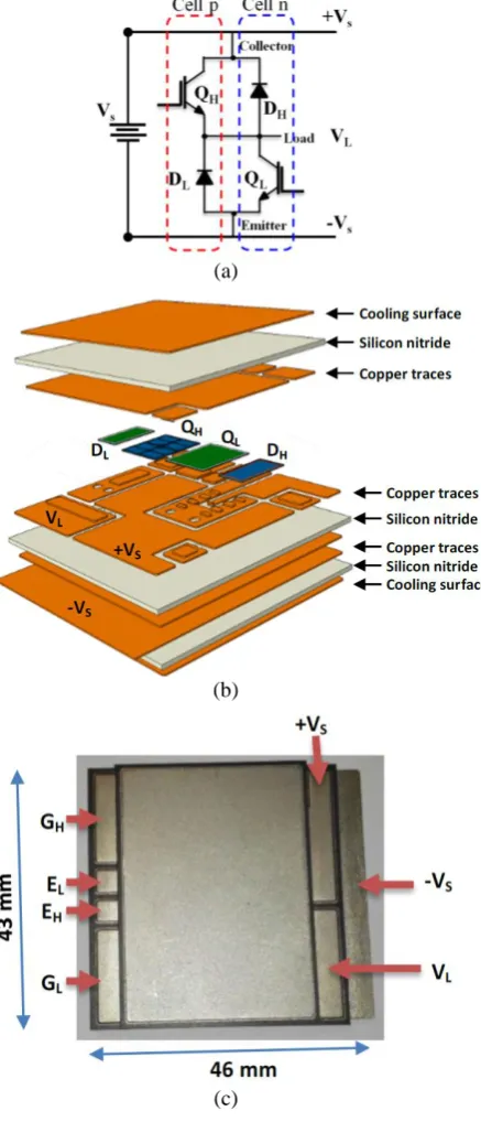
2. The double flat power switch
(a)
(b)
[image:2.595.75.294.119.629.2](c)
Fig. 1. Configuration of HBS: a) schematic diagram; b) exploded view of the stacked HBS; c) picture of the HBS
prototype.
This novel assembly is designed for high frequency plug in connectors, allowing optimization of performance, reliability and availability of the power system by means the following features.
Performance - The highly integrated double-sided cooled fully-bond-wire-less switch construction, with high-frequency-compatible interconnections at system level, enables improvement of: a) EM performance, with reduction of electrical (reduction/ elimination of voltage overshoot) and electro-thermal (reduction of switching losses) stresses on Si devices; b) power density, by the highly integrated nature of the solid-state switch, and embedment of passives and auxiliary electronic components (e.g., gate-drivers, sensors) within the connector framework.
Reliability - Thermo-mechanical stress and resulting degradation can be reduced by containing temperature swings (by direct substrate cooling), and improving temperature gradients (effect of double-sided cooling) in the power device structure.
Availability - The modular assembly approach enables for enhanced system maintenance and repair, requiring only the replacement of the individual system component that has failed. This can have a significant impact on the running cost of the equipment in some application.
The bottleneck of this solution could be the high power density, which implies the use of highly efficient heatsinks (e.g. air forced or liquid cooling). In this case the possibility of a double-sided cooling has been exploited, because of the stacked layout of the HBS.
The next section illustrates a modular prototype integrating HBS, double-side liquid cooler and customized connectors to interface quickly gate-driver, input, and load side PCBs.
3. The integrated HBS module prototype
In order to optimize the prototype, new quick-mount connectors with integrated capacitors and resistors have been designed between the module and the supply along with the load and drivers. Such interconnect reduces the volume of the system as much as possible and enables quick mounting. Integrated capacitors decouple the DC source by the high frequency oscillations generated during switching, thus reducing the hassle in the design of the whole conversion system. Fig. 2 reports a schematic of a single-phase inverter made by the HBS module.
Fig. 2. Schematic of a single-phase inverter made with an HBS module. The green sections can be made by PCBs.
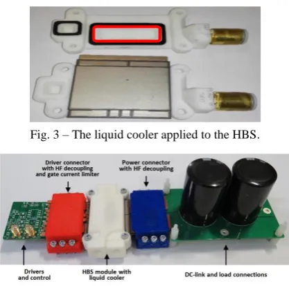
3.1. The integrated liquid cooler
Since the total heat generated in the HBS has been estimated to be up to 300 W, it is necessary to use a highly efficient cooling system, therefore an ad-hoc double-side liquid cooler was designed. The water cooling system flow path was conceived to directly target to the hot spot (open area in the red rectangle shown in Fig. 3), where the power devices are located. The liquid flows from the inlet toward the top cooling surface, turns down, and flows via the bottom cooling area of the switch to the outlet. Rectangular gaskets were designed to seal the plastic and the switch cooling surface. Finally, the cooling system is assembled and fixed using screws. A photograph of the whole integrated inverter module prototype is shown in Fig. 4. It is worth to note that this is a laboratory prototype, not optimized for long term reliability. Material choice options are available (including Aluminum) to ensure long lifetimes. Sealing can also be enhanced in a number of ways to contribute to structural stability and integrity.
Fig. 3 – The liquid cooler applied to the HBS.
Fig. 4. Assembled hardware of the single-phase inverter made with an HBS module.
4. FE thermal model tuning
[image:3.595.326.505.237.434.2]As stated above, the optimization of the cooling system was supported by FEM analysis. Using COMSOL Multiphysics, it was set a model of the heat transfer coupled to the fluid flow of the liquid cooler assembled with the HBS. Fig. 5 shows the geometry of the liquid cooler without the HBS and the geometry of the coolant, while Fig. 6 shows the geometry of the cooler+HBS.
Fig. 5. 3D geometry of the liquid cooler: heatsink with the boundary conditions of the heat transfer physic (top); coolant circuit with the boundary conditions of the fluid
flow physics (bottom).
Fig. 6. 3D geometry of the cooler+HBS assembly.
The low Reynolds number suggests a laminar flow. The physical properties of the coolant (water-propylene glycol40%vol), were used as in [11]. A flow rate of 2
l/min was set at the inlet and a pressure condition (taken as reference pressure) po = 0 was set at the outlet. At all the other boundaries of the coolant a no slip condition was considered. More details about the fluid-dynamic physics settings can be found in [12,13]. For the heat transfer physics, the boundary conditions were as follows:
- fixed temperature at the cooler inlet (25 °C);
[image:3.595.318.517.464.565.2] [image:3.595.73.282.493.700.2]versor, and is the heat flux density, at the outlet; - natural air convection: q = hair (Tamb – T), where
hair is the convection coefficient), at all the boundaries exposed to the air;
[image:4.595.87.270.283.386.2]- q = hmetal (Tref – T), at the metallic boundaries of the HBS that are in contact with other components of the system (clips of the power edge connectors). The heat transfer coefficient hmetalwas taken as 1000 W/m2K (a typical value between two metal bodies in contact), while the value measured by the IR camera on the metal clips of the connectors was chosen as reference temperature. The heat sources depicted in Fig. 7 were set in the subdomains representing the silicon dice of diodes and IGBTs.
Fig. 7. A transparent wireframe rendering of the HBS; highlighted blue the vias; in orange the silicon volume of
the IGBTs; in red the silicon volume of the diodes.
In order to tune the convective heat transfer coefficient h in the model within the range of variability, a thermal characterization was performed on the prototype at thermal steady state and known operating conditions (Tab. 1), by means of an infrared (IR) camera and thermocouples (for more details about the tuning procedure, see [14]). Input and output power were measured by power meters and the dissipated power on every die was estimated by SPICE simulations. It is worth to note that the module prototype is not optimized from device and control point of view: on the contrary, highly dissipative devices look advantageous in this work, since thermal performance of the package are addressed.
Tab 1. Thermal measurements operating conditions.
Parameter Value
Input voltage 298 V
Input power 1037 W
Output voltage 160 V
Output power 857 W
Power losses 180 W
Temperature at the inlet 25 °C
Flow rate 2 l/min
Ambient temperature 24 °C
A switching frequency of 10 kHz was selected for the HBS prototype. The cooling liquid inlet temperature was regulated to 25 °C by a liquid cooling system (Thermo Fisher Artic A25-SC100 refrigerated/ heated bath circulator) and a 40% less toxic propylene glycol was used for corrosion and frost protection. The top surface of the cooler was painted with high emissivity coating, to improve the thermal efficiency of the IR camera shoot.
In Fig. 8 the external thermal map measured by the IR camera is compared with the thermal map of the same surface simulated after model tuning (only the power section, without drivers and load was simulated). Although the small temperature variations measured on the surface do not allow an accurate evaluation of the error, the whole simulated thermal behaviour appears quite similar to the measured one. As can be noted in Fig. 9, at these operating conditions the simulated maximum temperatures of IGBTs and diodes were 58.1 °C, 58.6 °C, 68.1 °C, 66.8 °C for QH, QL, DH, DL,
respectively.
[image:4.595.310.525.365.480.2]
Fig. 8. Measured (left) and simulated (right) thermal map on the upper surface of the cooler+HBS assembly at the
[image:4.595.324.508.532.687.2]steady–state operating conditions of Tab. 1.
[image:4.595.73.253.612.724.2]5. Thermal simulations at extreme operating conditions and cooler optimization
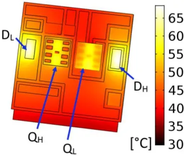
The FE model was used to analyse the module thermal behavior at extreme operating conditions.
Figs. 10 and 11 report the thermo-fluid dynamic simulation results for an extreme application (Tamb = 24 °C, Tinlet = 25 °C, Pdiss= 300 W, flow rate = 2 l/min), showing the high thermal performance obtained: the maximum temperatures reached on IGBTs and diodes were 79 °C, 78.7 °C, 92.7 °C, 94.8 °C for QH, QL, DH,
DL, respectively, values which are plenty below the
[image:5.595.317.517.214.481.2]maximum allowable.
[image:5.595.76.282.273.373.2]Fig. 10. Simulated internal temperature distribution (left) and cooler’s external boundaries thermal map (right). Tamb=24°C, Tinlet =25°C, Pdiss=300 W, flow rate =2 l/min.
Fig. 11. Coolant (60% water, 40% propylene glycol) temperature distribution, at the same conditions of Fig. 10.
With FE simulations the effect of an increase of the fluid flow rate was explored, up to 12 l/min, which is the maximum capability of most of the cooling systems. The maximum temperature reached by the hottest diode with Pdiss = 300 W was 81.7 °C, 75 °C,
72.3 °C, with 4, 8 ,12 l/min, respectively.
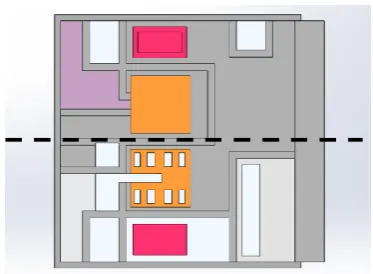
Although the thermal performances of the prototype are already satisfactory, the developed FE thermo-fluidynamic model allows to study improved solutions for the cooler, both with laminar and turbulent paths. As an example, Fig. 12 shows a possible solution with a symmetric cooling system
[image:5.595.93.266.424.554.2]using two separated coolers. To a first approximation, as confirmed since the early simulations of the HBS, from the thermal point of view it can be considered symmetrical respect to a plane passing through the dotted lines in Figs. 12 and 13. Thus, in this case it is possible to reduce the degrees of freedom of the numerical model, simulating only a half of the 3D domain of the HBS+coolers.
Fig. 12. Cross section of the improved cooling system (top); 3D geometry of cooler with central impingement
(bottom).
Fig. 13. Top view of the HBS without the layers over the IGBTs and the diodes.
[image:5.595.323.510.516.653.2]with respect to the present solution. The aim is to reduce as much as possible not only the maximum temperature but also the thermal gradient.
The results of the simulation when Tinlet = 25 °C,
[image:6.595.85.271.236.357.2]Pdiss= 300 W, and a flow rate of 1 l/min at the inlet of each cooler, are shown in Figs. 14-16. The streamlines in Fig. 14 gives an idea of the fluid vorticity, which, without stagnation, further improves the heat removal, even though the flow still is laminar (vorticity has not to be confused with turbulence).
Fig. 14. Improved double cooler: streamlines of the simulated flux of the coolant with a slice of the speed field
[image:6.595.97.260.403.510.2]at the same operating conditions of Tab. 1.
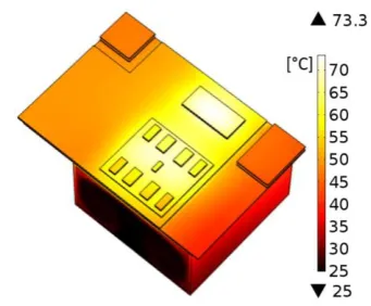
Fig. 15. Simulated thermal map with the improved double cooler: view from the IGBT side (middle section) at the
same operating conditions of Tab. 1.
Fig. 16. Simulated internal temperature distribution with the improved double cooler at the same operating
conditions of Tab. 1.
In this case the maximum temperatures on IGBTs and diodes were 70 °C and 73.3 °C, respectively, with a remarkable improvement with respect to the present prototype. This solution could be more difficult to integrate in a simple way, and a trade-off with fabrication costs and easy assembly is necessary, but it shows the potential of the adopted approach.
6. Conclusions
An innovative integration scheme for power switches was presented, which brings along advanced electro-thermal and electro-magnetic performance as compared with traditional construction technology. The proposed solution enables the development of modular power converters, thus potentially enabling significant gain in system level maintenance cost, which, again, is likely to offset any extra cost incurred due to initial higher price.
The paper focused on the thermal performance of the liquid cooled assembly at normal and extreme operative conditions. A FEM thermo-fluidynamic model was built and tuned by thermal measurements performed on an early prototype. FEM simulations enabled to investigate the temperature map inside the package, looking at the thermally most critical components, and confirmed the capability of dissipating more than 300 W by the module, without reaching the maximum operating temperature on the active devices.
Moreover, by the FE thermo-fluidynamic model, improved solutions were studied, and one of them was shown, as an example, which is able to even extend the module power density, once a further step of engineering will be done, to make the design suitable for industrial production.
References
[1] B.C. Charboneau, F. Wang, J.D. Van Wyk, D. Boroyevich, Z. Liang, E.P. Scott, C.W. Tipton, “Double-sided liquid cooling for power semiconductor devices using embedded power packaging”, IEEE Trans. Ind. Appl., vol. 44, no. 5, pp. 1645-1655, 2008. [2] “DENSO develops high output power control unit and battery cooling system for hybrid vehicles”. DENSO news ref. N. D0705 05/31/2007, 2007.
[3] X. Cao, T. Wang, Z. Tan, K. Ngo, S. Luo, G.-Q. Lu, “Development of a double-side cooled power module joined by low-temperature sintering of nanosilver paste for electric vehicles”, in IMAPS’s 2nd
[image:6.595.90.261.547.688.2][4] J. Marcinkowski, “Innovative CooliR2 TM packaging platform with dual-side cooling advances HEVs and EVs”, IR technical paper, www.irf.com/technical-info/whitepaper/coolir2d.pdf.
[5] M. Schneider-Ramelow, “Design and assembly of power semiconductors with double-sided water cooling,” proc. 5th
International Conference on Integrated Power Systems (CIPS), 2008, pp. 1-7. [6] M. Meisser, D. Hamilton, T. Blank, P. Mawby,
“Low-inductive compact SiC power modules for high-frequency operation”, proc. PCIM Europe 2014. [7] M. Schmenger, M. Meisser, D. Hamilton, B. Leyrer,
M. Bernd, P. Mawby, T. Blank, “Highly integrated power modules based on copper thick-film-on-DCB for high frequency operation of SiC semiconductors -design and manufacture”, proc. 17th
EPE Conf., 2015. [8] A.K. Solomon, A. Castellazzi, N. Delmonte, P. Cova, “Highly integrated low-inductive power switches using double-etched substrates with through-hole viases”, proc. ISPSD, Hong Kong, 2015, pp. 329-332. [9] A. K. Solomon, A. Castellazzi, N. Delmonte, P. Cova,
“Modular power converter integration based on non-conventional power switch assembly and interconnects”, Proc. 9th
ICPE 2015-ECCE ASIA, Seoul, Korea, Jun. 1-5, 2015, pp. 837-843.
[10] A.K. Solomon, A. Castellazzi, N. Delmonte, P. Cova, “Modular plug-in high-performance assembly of a power converter”, accepted at 18th
EPE Conf., 2016. [11] “Engineering and operating guide for DOWFROST and DOWFROST HD inhibited propylene glycol-based heat transfer fluids”, The Dow Chemical Company, 2008.
[12] P. Cova, N. Delmonte, F. Giuliani, M. Citterio, S. La Torre, A. Lanza, M. Lazzaroni, “Thermal modeling and characterization of power converters for LHC power supplies”, In: Proc. 12th IMEKO TC10 Workshop on Technical Diagnostics - New Perspectives in Measurements, Tools and Techniques for Industrial Applications, Firenze, Italy, Jun. 6-7, 2013, pp. 202-207.
[13] P. Cova, N. Delmonte, F. Giuliani, M. Citterio, S. Latorre, M. Lazzaroni, A. Lanza, “Thermal optimization of water heat sink for power converters with tight thermal constraints”, Microel. Reliab. 53 (2013) 1760-1765.