Regular Stereo Matching Improvement System Based on
Kinect-supporting Mechanism
Din-Yuen Chan, Che-Han Hsu
Department of Computer Science and Information Engineering, National Chiayi University, Chiayi City, Chinese Taipei Email: {dychan, s1000436} @mail.ncyu.edu.tw
Received2012
ABSTRACT
In this paper, we built a stereoscopic video associated experimental model, which is referenced as Kinect-supporting improved stereo matching scheme. As the depth maps offered by the Kinect IR-projector are resolution-inadequate, noisy, distance-limited, unstable, and material-sensitive, the appropriated de-noising, stabilization and filtering are first performed for retrieving useful IR-projector depths. The disparities are linearly computed from the refined IR-projector depths to provide specifically referable disparity resources. By exploiting these resources with sufficiency, the proposed mechanism can lead to great enhancement on both speed and accuracy of stereo matching processing to offer better extra virtual view generation and the possibility of price-popularized IR-projector embedded stereoscopic camera.
Keywords: Stereo Matching; Image Registration; Kinect; IR-Projector Image
1. Introduction
Multi-view video systemization is the most emerging subject for bare eyes stereo vision. The camera array is utilized for the promising implementation in multi-view manufacture [1]. Generally speaking, the camera array applied to multi-view video photography is not suited for dynamic setups. The pre-processing filter is specified to modify the depth map for sustaining fewer holes in syn-thesizing another view [2]. If the filter is only designed for holes reduction [2], the side effect such as bending distortion [3] is hardly inevitable. Moreover, the one view with single-channel depth using DIBR is rather difficult to obtain adequate view angle extensions. With low-labor calibration, the binocular 3D-camera is ac-knowledged by proper equipment to straightforwardly capture the stereoscope two-view videos. However, when the depth decision fully leans on the stereo matching of paired color images, the suited depth acquisition of sparse-texture is quite difficult. In general, the IR-sensor emitting infrared (IR) for stably acquiring depths is usually expensive [4], and cannot completely sense ma-terials being IR-detection unavailable. Therefore, a more valuable approach shall attempt to implement a common low-cost IR-sensor into an efficient auxiliary apparatus for generating high-quality depths. The Kinect IR-projector is not really considered to be useful for depth measurement due to its low spatial/depth resolution, distance-limited sensing and unstable depth capture, dif-ficultly of detecting specular, transparent, and reflective
objects. However, Kinect has become a very popular, low-price off-the-shelf depth detector nowadays; the ste-reoscope investigation based on Kinect begins emerging [5].
In [5], the work first performs the stereo matching between Kinect’s IR-image and RGB image to generate a depth map. The depth map and the inner depth map are then computed using Kinect IR-projector captured pat-terns are fused for accomplishing a more qualified depth map. Because the captures of IR and RGB images by Kinect are in turn active, rather than synchronous, the mechanism [5] seems efficient, but at most only suited for monotonous, low-activity videos.
Theoretically, by adding an IR sensor, the handling of stereo matching problem shall become much easier. In effect, to effectively integrate two hetero images of large quality difference, Kinect IR-projector image and 3D-camera image is quite a challenge task. Therefore, our work is to identify a valuable approach of developing an inexpensive IR-sensor embedded 3D-camera for faci-litating the multi-view manufacture can be obtained. Be-cause the high-resolution depth maps can be easily yielded by operating stereo matching on the captured two views of 3D-camera, the depths captured by Kinect IR-projector only play a reference/consultation role ra-ther than an arbiter in stereo matching operations.
Ki-nect can offer the necessity of inter-medium for difficult image registration from 3D camera color images to con-currently captured IR-projector depth images.
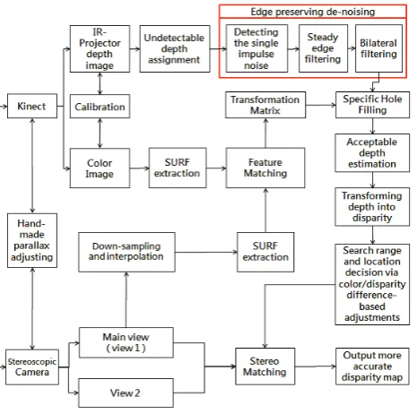
Figure 1. Processing flow of the proposed system.
The proposed system contains a series of appropriated re-finement processing on the IR-projector image, the regis-tration from the main view image to the IR-projector depth image, and the stereo matching improvement supported by the refined IR-projector image, as shown by Figure 1. The computation of homographic transform matrixes for the registration between Kinect and 3D-camera images is the most complex part in the proposed system, but only per-formed once at the initialization of depth generation of a 3D video sequence.
2. Cross Geometrical Image Relation
Identification
The most troublesome barrier is the large content differ-ences between 3D-camera color image and IR-projector depth image in their registration. Since the Kinect add-on color image can be easily calibrated to the IR-projector depth image synchronically captured, it is a good inter-mediate interface for the following registration. Specifi-cally, the mapping for image registration will run from 3D-camera main view image to Kinect add-on color im-age, and then to IR-projector depth image. For well mu-tual images registration, the geometrical image relation identification need to be performed in advance so it in-cludes the image localization (partition) by analyzing feature points distribution and the global transition regis-tration by selecting a representative regisregis-tration feature point based on the precedence of center location and
sa-lient response strength.
Generally speaking, the 3D camera and the Kinect sensor are not difficult to obtain adequate parallelization of photographing planes via hand-made adjustment for constrain their perspective difference as much as possible. Therefore, the remaining registration task is to find the relative transition and rotation between two frames cap-tured by them. The implementation of relating the global center registration between 3D camera Image and Kinect Color Image is depicted as below.
For simplifying the registration of two images with large-scale resolution difference, the faster way is to pull down the resolution of high-resolution image to com-promise low-resolution one. Therefore, in the study, the main-view color image of 3D camera (abbreviated as MCI) is made large-scale down-sampling and then small-scale linear interpolation to attain same low hori-zontal/vertical resolutions as Kinect RGB image. Before computing the image registration (homographic trans-form) matrix, the relative global location difference be-tween the resolution-reduced main-view color image (RMCI) and the Kinect color image (KCI) need be esti-mated in advance. Such a location difference need be shift back for the translation of two targeted images dur-ing performdur-ing their registration. In this work, a center zone in RMCI is allocated to extract several speeded up robust features (SURFs), of which their response strengths can exceed a given threshold, as the candidate anchor nodes. The simultaneously sampled KCI is also extracted at the same number of SURFs as its candidate anchor nodes by the same way operated on RMCI. A double checking process is then utilized to identify the trustful reference points between two images for making the necessary global transition at the beginning of regis-tration. The process tests the anchor nodes one by one from the place nearest the mask center to those around the mask borders in the clockwise or counter-clockwise direction by two phases shown as follows.
Phase 1 < Collecting a couple of qualified anchor nodes >
Step 1. Check if two qualified anchor nodes (QANs) have been acquired in the main view color image, and their corresponding feature nodes matched in the si-multaneous Kinect color image. If it does, go to Step 5 (the second phase). Otherwise, go to the next step.
Step 2. Select a candidate anchor node on the main view image as the new test one. When a previous QAN exists, the selection shall be set a shortest dis-tance from the last qualified anchor points (QAP).
Step 3. Compute the difference between the characte-ristic vectors of new test node and its corresponding feature node best-matched in Kinect color image.
back to Step 2.
Phase 2 < Fast Checking of geometrical similarity >
Step 5. Line two QANs to get a straight segmental line in the main view color image, so does their matched feature nodes to get another segmental line in the simultaneous Kinect color image.
Step 6. If the two segmental lines have similar slopes and length, both after normalizing them by the raster scanning ratios and the resolutions of these two regis-tration-targeted images, then the QAN having the lower characteristic-vector difference among two QANs is identified as the trustful reference point, and stop the routine. Otherwise, give up the QAN of larg-er charactlarg-eristic vectors, and then go back to Step 2. The scheme will set the normalized coordinate differ-ence vector between trustful referdiffer-ence point and its cor-responding feature node as the global transition vector for the main view color image and the simultaneous Ki-nect color image.
3. Undetectable Depth Assignment and
Edge Preserving De-noising
For better promoting the utilization confidence of IR-projector depth image, IR-projector depth image after undetectable depth assignment and edge preserving de-noising will be further refined by three proposed processes. The first step of the process is to detect the single impulse noise in the IR-projector depth image by subtracting the strength of each pixel (sensed depth value) and the strengths of its 8 neighbors. If all the 8 subtraction outcomes of a pixel are larger than a threshold, this pixel is regarded as single impulse noise. The strength of this pixel is then replaced by the mean of the 8 neighboring strengths for removing its impact on the subsequent processes, the processed image is called the impulse-noise dropped IR-projector depth-image (IDIRI). The second process is for marking the so-called steady edges. Via performing the Sobel-filter filtering on IDIRI, each edge point is examined whether its filtered intensity is similar to anyone of its 8-neighboring filtered intensities or not. If it does, this point is denoted as a steady edge point. For simply enhancing the effect of edge preserving via bila-teral filtering, the procedure of bilabila-teral filtering proposed herein will skip over the steady edge points. Except the steady edge points, of which set is grouped as set Gssp, the
remaining points of IDIRI are performed by an appro-priated bilateral filter with adaptive piece-wise mask. Through the bilateral filtering of window size of (2L+1)×
(2L+1), The filtered intensity at (x, y), denoted by ISIR(x,
y), is given by
∑ ∑ ∑ + + =− =− + + − ∈ + + ⋅ = L L i L L
j xiy j IR IDIRI ssp
j y i x SIR G G y x for j y i x I y x I ) , ( ) , ( 1 ) , ( , , ω ω
where IIR(x+i, y+j) is the pixel intensity at point (x+i, y+j)
on IDIRI, of which pixels set is GIDRI, and its filter weight
is Ѡx+i, y+j . In (1), Ѡx+i, y+j has two ingredients multiplied
together :
( )
j i j y ix , 2 ( i,j 1) u
β
,ω
= −α − ⋅+ +
for bilateral effects on the spatial distance and the inten-sity difference, where u(.) is the unit step function. The spatial weighting function 2−(αi,j−1) is piece- wise, where
max
(
,
,
1
)
,j
i
j
i
=
α
the intensity weighting function u(βi, j) exploits u(.) for
displaying the characteristic of a bi-level valued mask, where ) , ( ) , (
,j TIR IIR x y IIR x i y j
i = − − + +
β
The bilateral filter applies several window sizes, where
L and its maximum, denoted by Lmax, are proportional to
the quantized IIR(x, y) and the standard deviation of
quan-tized IIR(x, y), respectively, on the impulse-noise dropped
IR depth image. More specifically, the point closer to the camera (with the larger depth value) will be filtered by the bigger filtering window. The larger standard devia-tion of quantized IIR(x, y) will cause the smaller Lmax
ap-plied.
4. IR-Projector Supported Stereo Matching
Improvement
The candidate anchor nodes of paired RMCI and KCI are treated as targets of Random Sample Consensus (RAN-SAC) processing to obtain the registration matrix for the registration achievement between the pixels of KCI and that of MCI.
4.1. Adjustment of Referred Search Location
and Search Region
The computed by Kinect IR-projector detected depth can offer good and fast search references in the search of two views stereo matching. Further adjustment is necessary, if two adjacent pixels having close chro-minance and luchro-minance but quite different search ref-erence positions referred by the IR-projector image. Such a case usually happens nearby the borders of two occluded objects. In this case, the suspected search reference location shall be replaced by a higher confi-dence one, but in practice, the definition or measure-ment of confidence is not easy. For the views stereo matching from left to right, the computation of original search reference position at (x, y) is given by
p
x
y
(
I
x
y
)
x
IR ref
S_
(
,
)
=
Γ
(
,'
)'
−
where Γ(IIR(x’, y’)) is to linearly transform the depth
value IIR(x’, y’) at (x’, y’) in the IR-projector image to the
. (1)
. (2)
. (3)
. (4)
disparity of pixel at (x, y) in the left view image that (x’, y’) is registered to (x, y) by the obtained registration ma-trix. The search range centered at PS_ref (x, y) is then set
as
(
( ,' )')
, ( , )(
( ,' )')
]) , (
[pS_ref x y −χ IIR x y pS_ref x y +χ IIR x y
to find an adequately matched pixel on the right view image that the searching offset χ(IIR(x’, y’)) is a variable
according to IIR(x’, y’). In (5) and (6), Γ(.) and χ(.) are
mainly relevant to the display screen parameters and the dynamic range of IR-projector captured depths.
4.2. Pixel Extrapolation Outsides the
IR-Projector Image Region
When the registered location of referred point in the IR-projector image exceeds the image region, the ef-fective extrapolation is necessary for figuring out the depth value in that location. Since the pixel extrapola-tion can be considered as the extension of image size, therefore a continuity-preference predication is able to be addressed to extend the IR-projector image. The registered pixel exceeding yet still contacts the border of current extended IR-projector image will have three (or two) neighbors, which has the depth values (IR-projector detected intensities), among its 8-nrighboring locations. Assume the pixel position is (x’, y’). The connection straight line among the other three connection straight line radiated from (x, y) has the lowest depth change is selected such that the difference of successive two pixels on it will be adopted to extrapo-late the pixel intensity at (x, y). The continuity-preference predication to predict the pixel intensity at (x, y), denoted by ĨIR(x, y), is formularized by
( )
( ) ( )
(
I x x y y I x x y y)
y y x x I y x I
IR IR
IR IR
∆ + ∆ + − ∆ + ∆ +
+ ∆ + ∆ + =
2 , 2 ,
, )
, ( ~
where (∆x = 1,∆y = γ), (∆x = −1,∆y = −γ), (∆x = γ−1,∆y
= 1) and (∆x = −γ−1,∆y = −1) are set for extrapolating
(extending) the exterior pixel along the left border, the right border, the bottom, and the top of IR-projector image, respectively. Parameter γ as the slope of e con-tinuity preference is given by
(
)
(
)
+∆ +∆ − + ∆ + ∆
=
∈ I x xy y I x xy y
Min
Arg ρφ IR , IR 2 , 2
γ
where ρ expresses the slope of two-point straight line and the set of ρ’s is ϕ, which equals to {−1, 0, 1} for extending the image outward its left/right border, and {−1, ∞, 1} outward its bottom/top border.
4.3. False-Reduced Modification for Stereo
Matching Search References
After applying the homographic transform matrix to map coordinates from IR-projector image to the main
view image, the necessary adjustment of original search locations will be set for rational relations rather than accurate status from the point of geometrical view. The proposed method is following and exploiting the raster-scan processing order for prompt adjustment that its procedure is depicted as follows. For the non-leftmost pixels at (x ≠ 0, y)’s, if the criterion below is satisfied:
C y x y
x, )− ( −1, )<δ
( C
C pS_reft(x,y)−piS_ref(x− ,1y)>δS
then PS_ref (x, y) is replaced by PS_ref (x−1, y) that C(x, y)
is the color vector at (x, y), δC and δS are empirical
thre-sholds. Similarly, for the leftmost pixels at (0, y)’s, if the criterion given by
C y x y
x, )− ( , −1)<δ
( C
C pS_reft(x,y)−pS_ref(x,y−1)>δS
holds, then PiS_ref (x, y−1) substitutes for PS_ref (x, y).
For alleviating the miss-matching error resulting from unsuitable modification in suspected PS_ref (x, y), the
search region for the pixel at (x, y) is enlarged for making a protective compensation in stereo matching. The adopted straightforward way is to add a fraction of δS to
the search distance.
4.4. Stereo Matching Acceleration by IR-
Projector Depth Image
For facilitating the mapping between refined IR-projector depths and stereo matching depths as well as removing wrong or inappropriate differences in flat zones, the above refined IR-projector depth is quan-tized in advance. Then, the level mapping relation, which is associated with dynamic regions registration and one-on-one statistic observation, between the ste-reo matching depth and the above-refined IR-projector depth can be statistically estimated. Its formula is treated as a mutual mapping function of heterogeneous depths. Thus, via the heterogeneous mapping of refined IR-projector depth to 3D camera dual images, the ini-tial search coordinate can be obtained to improve both of speed and accuracy of the stereo matching for the depth computation in testing point. This is suited for all of existing stereo matching algorithms including sup-porting weight [6], cross-based and census transform ones [7].
(a) (b)
Figure 2. (a) Original IR-projector image (b) Refined result.
. (6)
. (7)
. (8)
. (9) and
[image:4.595.311.535.609.698.2]5. Simulation Results
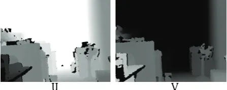
In our experiments, the stereo matching adopts AD- Census method [7] to find the best matched point in right view images from the left (main) view ones. Figure 2 displays an original IR-projector image and its refined result with the proposed processes, the refinement speed of IR- projector can obtain to 30 frames per second. It demonstrates that the refined IR-projector images are quite stable that various noise, photography artifacts, and IR-detection unavailable parts causing IR-sensed image holes can be removed. In Figure 3, the stereo matching outcomes without and with the proposed Kinect-sup- porting improvement are compared. By the Kinect-sup- porting improvement, the stereo matching accuracy can be raised especially for the fatness or sparse-texture parts.
The Kinect-supporting stereo matching against original stereo matching speed-up is 34.08%, and the frame- by-frame computational overheads acquiring the referred search points are counted in the former except for homo-graphic transform matrixes generating, which belongs to the system-setup initialization.
(a) (b)
Figure 2. Depth Maps of Stereo matching:(a) without Kinect supporting (b) with Kinect supporting
6. Conclusion
In this study, a Kinect-supporting mechanism with regu-lar structure is proposed for efficiently improving the stereo matching processing. Through proposed differ-ent-resolution hetero-image registration, the disparities linearly computed from those refined IR-projector depths are applied to the main view color image of 3D camera as disparity searching references. By concisely exploiting the disparity reference resources, the proposed scheme
can lead to the effectiveness of promotion for the accu-racy and speed of stereo matching. This investigation indicates that developing a low-cost IR-sensor embedded 3D-camera, by which the multi-view video beyond five views generation can be manufactured rapidly as soon as users (or artist) shoots a two-view video sequence.
7. Acknowledgements
The author would like to thank the fund support by NSC 101-2221-E-415-020- and 101-EC-17-A-02-S1-201.
REFERENCES
[1] Y. Taguchi, T. Koike, K. Takahashi, T. Naemura, “TransCAIP: A Live 3D TV System Using a Camera Ar-ray and an Integral Photography Display with Interactive Control of Viewing Parameters,” IEEE Transactions on Visualization and Computer Graphics, vol.15, no.5, pp.841-852, Sep. 2009.
[2] W. J. Tam, G. Alain, L. Zhang, T. Martin, R. Renaud, “Smoothing depth maps for improved stereoscopic image quality,” Three-Dimensional TV, Video, and Display III(Proceedings of the SPIE), Vol. 5599, pp. 162-172,2004.
[3] L. Zhang, W.J. Tam, “Stereoscopic image generation based on depth images for 3D TV,” IEEE Transactions on Broadcasting, vol.51, no.2, pp.191-199, Jun. 2005. [4] J. Zhu, L. Wang, R. Yang, J.E. Davis, Z. Pan, “Reliability
Fusion of Time-of-Flight Depth and Stereo Geometry for High Quality Depth Maps,” IEEE Transactions on Pattern Analysis and Machine Intelligence, vol.33, no.7, pp.1400-1414, Jul. 2011.
[5] W.C. Chiu, U. Blanke, M. Fritz, “Improving the Kinect by Cross-Modal Stereo,” The 22nd British Machine Vi-sion Conference (BMVC 2011), pp.116.1-116.10, Sep. 2010.
[6] K.J. Yoon and I.S. Kweon, “Locally adaptive sup-port-weight approach for visual correspondence search,” Proceedings of the IEEE Computer Society Conference on Computer Vision and Pattern Recognition, vol. 2, pp.924-931, 2005.
[image:5.595.59.288.369.469.2]