204
©IJRASET: All Rights are Reserved
ARM based Educational Kit for Blind Student
Madhuri S. Gangdhar1, Prof. S. A. Patil2 1
Department of Electronics, DKTE College, Ichalkaranji
Abstract:We propose the use of a touch screen to convey basic mathematical concept, general knowledge information through
simple educational kit. It is robust and simple to control. It is activated by touch only. Blind children can choose activities by touching the touch screen guided by pointers placed at the side of touch screen. The main Idea behind the project is to design a handy educational embedded device which can be used by the visually impaired. For this purpose we make use of combination of micro- controller, graphics LCD, touch screen, SD card interface etc.
Keywords: ARM, Graphical LCD, SD Card interface, Touch screen, Math Education, Blind, Speaker.
I. INTRODUCTION
From small handheld devices to large industrial consoles, touch screens are rapidly becoming common interfaces, allowing people to interact with information using their fingertips. A number of different technologies have been explored over the past few years to endow touch screens with graphical interface. Perhaps the simplest way to create touch screen based voice feedback is to design an education frame work on the graphics LCD and layover a touch screen over the display. For the blind, the lack of sight is a major barrier in daily living: information access, mobility, way finding, Interaction with the environment and with other people, among others, are challenging issues. Blind children may also need special training in understanding spatial concepts, and in self-care, as they are often unable to learn visually and through imitation as other children do.
II. SYSTEMDESIGN
Our system consists of five main components: ARM, Resistive touch screen, graphical LCD, SD card, speaker.
Fig.1: Block Diagram of system
A. ARM
The ARM7TDMI-S is a general purpose 32-bit microprocessor, which offers high performance and very low power consumption. The ARM architecture is based on Reduced Instruction Set Computer (RISC) principles, and the instruction set and related decode mechanism are much simpler than those of micro programmed Complex Instruction Set Computers. This simplicity results in a high instruction throughput and impressive real-time interrupt response from a small and cost-effective processor core. Pipeline techniques are employed so that all parts of the processing and memory systems can operate continuously. Typically, while one instruction is being executed, its successor is being decoded, and a third instruction is being fetched from memory.
205
©IJRASET: All Rights are Reserved
execution at maximum clock rate. For critical code size applications, the alternative 16-bit Thumb mode reduces code by more than 30 % with minimal performance penalty.
Due to their tiny size and low power consumption, these microcontrollers are ideal for applications where miniaturization is a key requirement, such as access control and point-of-sale. With a wide range of serial communications interfaces and on-chip SRAM options of 8 kB, 16 kB, and 32 kB, they are very well suited for communication gateways and protocol converters, soft modems, voice recognition and low-end imaging, providing both large buffer size and high processing power. Various 32-bit timers, single or dual 10-bit 8-channel ADC(s), 10-bit DAC, PWM channels and 47 GPIO lines with up to nine edge or level sensitive external interrupt pins make these microcontrollers particularly suitable for industrial control and medical systems.
B. Touch Screen
A touch screen is an input device and normally layered on the top of an electronic visual display of an information processing system. A user can give input or control the information processing system through simple or multi-touch gestures by touching the screen with a special stylus or one or more fingers.
A resistive touch screen consists of top and bottom transparent sheets facing each other with a gap between them. The top and bottom sheets are coated with ITO (Indium Tin Oxide). ITO is a transparent conducting material. The top and bottom sheets have uniform resistance value over its surface.
[image:2.612.194.418.366.532.2]As the top sheet gets pressed, the pressed point of the top sheet physically yields and contacts the bottom sheet. As the ITO layers of the top and bottom sheets contact, electricity gets conducted at the contacted point, and the location of the conducted point is detected. The material of the top sheet must be flexible, because it needs to yield when pressed. PET film, glass or polycarbonate plastic is most commonly used. The most basic combination is PET film as top sheet and glass as bottom sheet (film/glass structure). Spacer dots are usually printed on the bottom sheets to prevent the top and bottom sheets from contacting when not pressed. Size and placement of the dot spacers affect the operational feeling.
Fig 2: Resistive Type Touch Screen
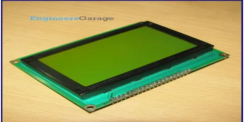
C. Graphical LCD
This LCD has a display format of 128x64 dots and has yellow-green colour backlight. Each LCD needs a controller to execute its internal operations. This LCD uses two KS0108 controllers.
[image:2.612.185.427.595.716.2]206
©IJRASET: All Rights are Reserved
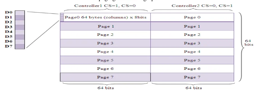
The 128x64 LCD is divided into two equal halves with each half being controlled by a separate KS0108 controller. Such LCDs (using KS0108 controller) involve paging scheme, i.e., whole LCD is divided equally into pages. The paging scheme of the graphical LCD can be easily understood from the following table.
Table1: paging scheme of graphical LCD
1) 128x64 LCD implies 128 columns and 64 rows. In total there are (128x64 = 1024) pixels.
2) 128x64 LCD is divided equally into two halves. Each half is controlled by a separate controller and consists of 8 pages. In above diagram, CS stands for Controller Select.
3) Each page consists of 8 rows and 64 columns. So two horizontal pages make 128 (64x2) columns and 8 vertical pages make 64
rows (8x8).
D. SD Card
Secure Digital (SD) is a non-volatile memory card format developed by the SD Card Association (SDA) for use in portable devices. Their small size, relative simplicity, low power consumption, and low cost make them an ideal solution for many applications. SD card is used to store all the audio signals, communication based protocol.
E. Speaker
Speakers are one of the most common output devices used with computer systems. Regardless of their design, the purpose of speakers is to produce audio output that can be heard by the listener. Speakers are transducers that convert electromagnetic waves into sound waves. The speakers receive audio input from a device such as a computer or an audio receiver. This input may be either in analog or digital form. Analog speakers simply amplify the analog electromagnetic waves into sound waves. Since sound waves are produced in analog form, digital speakers must first convert the digital input to an analog signal, and then generate the sound waves.In our system speaker is present at the output side of the design. This is the most important unit through the visually handicapped user’s point of view. User will interact with the device through speaker system .whatever activities the user is going to do will be announced by the device through speaker system.
III.RESULTS
[image:3.612.102.517.138.285.2]Results of the experiments are presented in order as displayed on LCD and announced by SD card. Figure 4 represents design of our system.
207
[image:4.612.163.465.89.315.2]©IJRASET: All Rights are Reserved
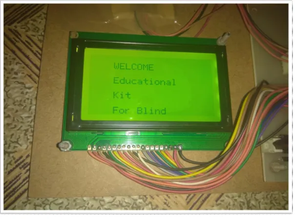
[image:4.612.129.486.365.510.2]Fig. 5 after starting the educational kit
Figure 5 shows result displayed on LCD after starting educational kit. The name of project displayed on LCD.
Fig. 6 Main menu of kit
[image:4.612.148.472.548.685.2]Figure 6 represents result when main menu displayed on LCD Screen. In main menu we give 4 options as shown in figure.
Fig 7 sub menu of Math’s displayed on LCD
208
[image:5.612.135.488.76.286.2]©IJRASET: All Rights are Reserved
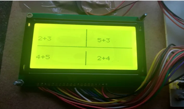
Fig 8 sub menu of addition
[image:5.612.149.476.337.551.2]Figure 8 displays result as we select addition menu. Here also we have given 4 sub menus as shown in figure.
Fig 9 result of 2+3 addition
Figure 9 displays result of 2+3 addition. Result displayed on LCD and announced via SD card in audio form.
IV.CONCLUSIONS
In this paper we have described development of simple educational kit capable of displaying mathematical concepts to blind children’s. Using such educational kit blind students can evaluate a variety of phenomena. These systems provide flexibility. For these systems we must evaluate our requirements for different functions like songs, pictures and quiz etc… Based on requirements we can choose touch screen , graphical LCD and hardware to meet our needs.
V. ACKNOWLEDGMENT
209
©IJRASET: All Rights are Reserved
REFERENCES
[1] Jenna L. Toennies, Jessica Burgner, Thomas J. Withrow and Robert J. Webster, “Toward HAPTIC/ aural touch screen display of graphical mathematics for
the education of blind students”. World Haptics, pp. 21-24. June 2011.
[2] Christensen, L. B., Keegan, S. J., Stevns, T., SCRIBE: “A Model for Implementing Robo Braille in a Higher Education Institution”, 13th International Conference on Computers Helping People with Special Needs, ICCHP 2012; pp. 77–83. July 2012.
[3] Fuentes Sepúlveda, J., Ferres, L., “Improving Accessibility to Mathematical Formulas: The Wikipedia Math Accessor,” New Review of Hypermedia and
Multimedia, vol. 18, Issue 3, pp. 183–204. Sept 2012.
[4] J. Jungil, Y. Hongchan, L. Hyelim and C. Jinsoo, “Graphic Haptic Electronic Board-based Education Assistive Technology System for Blind People,” IEEE
International Conference on Consumer Electronics, ICCE; pp. 364-365.2015.
[5] W.Yu and S.A.Brewster. “Evaluation of multimodal graphs for blind people.” Universal Access in the Information Society, Issue 2, pp.105–124. 2003.
[6] R. Velázquez, “Wearable Assistive Devices for the Blind.” Wearable and Autonomous Biomedical Devices and Systems for Smart Environment: Issues and
Characterization, LNEE 75, Springer, pp 331-349, 2010.
[7] Yu, W. and Kangas, K. (2003) ”Web-based haptic applications for blind people to create virtual graphs.’’ In, 11th Symposium on Haptic Interfaces for Virtual
Environment and Teleoperator Systems, pp. 318-325, March 2003.
[8] T. Watanabe, M. Kobayashi, S. Ono, and K. Yokoyama “Practical use of interactive tactile graphic display system at a school for the blind.’’ Current Developments in Technology-Assisted Education, pp. 1111–1115, 2006.
[9] O. Lahav, D. Mioduser “Haptic-feedback support for cognitive mapping of unknown spaces by people who are blind.” International Journal of Human-
Computer Studies, pp. 23-35, 2008.
[10] Wongkia W, Naruedomkul K, Cercone N “i-Math: Automatic math reader for Thai blind and visually impaired students” Computers and Mathematics with
Applications, vol. 64, Issue 6, Elsevier, pp. 2128-2140, sept 2012.
[11] Nazemi A, Murray I, Mohammadi N “Mathspeak: An Audio Method for Presenting Mathematical Formulae to Blind Students.” 5th international conference on
Human System interaction, June 2012.
[12] Yu, W. and Reid, D. and Brewster, S.A. (2002) “Web-based multimodal graphs for visually impaired people.” In, Keates, S., Eds. 1st Cambridge Workshop
on Universal Access and Assistive Technology (CWUAAT), pp. 25-27, March 2002.
[13] P. Blenkhorn, D. G. Evans, “Using speech and touch to enable blind people to access schematic diagrams”, international Journal of Network and Computer
Applications, vol. 21, Issue 1, pp. 17-29. January 1998.